Locomotive and freight car brakes (p. 209 of the report)
Train brakes
Locomotives are equipped with 2 air brake systems: automatic and independent.
The automatic brake system applies the brakes to each locomotive and to each car in the train as well; it is normally used during train operations to slow and stop the train.
Each locomotive also has an independent brake system, which applies air brakes on the locomotive only. Independent brakes are not normally used during train operations, but are primarily used as a parking brake, sometimes in conjunction with the hand brake on the locomotive.
Locomotives are also equipped with a dynamic brake (DB) system that makes use of locomotive traction motors to provide resistance against the rotation of axles. These brakes are also used during train operations to slow and stop the train.
Automatic brake system
A train’s automatic brake system is supplied with air from compressors located on each operating locomotive. The air is filtered, dried, compressed, and stored in the locomotive's main reservoirs. Air pressure in the main reservoirs is maintained between 130 and 140 psi. These reservoirs supply air to each locomotive and individual car in a train through a brake pipe that runs the entire length of the train. The brake pipe of each locomotive and rail car of the train is connected to that of the next locomotive or rail car by an end hose.
The automatic brake system is equipped with a regulating valve that is used to set the air pressure supplied to the brake pipe to approximately 90 psi.Footnote 1 Given a sufficient amount of time, the entire train brake system will charge to 90 psi. The time to fully charge a train brake system is dependent on train length, the ambient temperature, the positioning of locomotives throughout the train, and the amount of leakageFootnote 2 throughout the train.
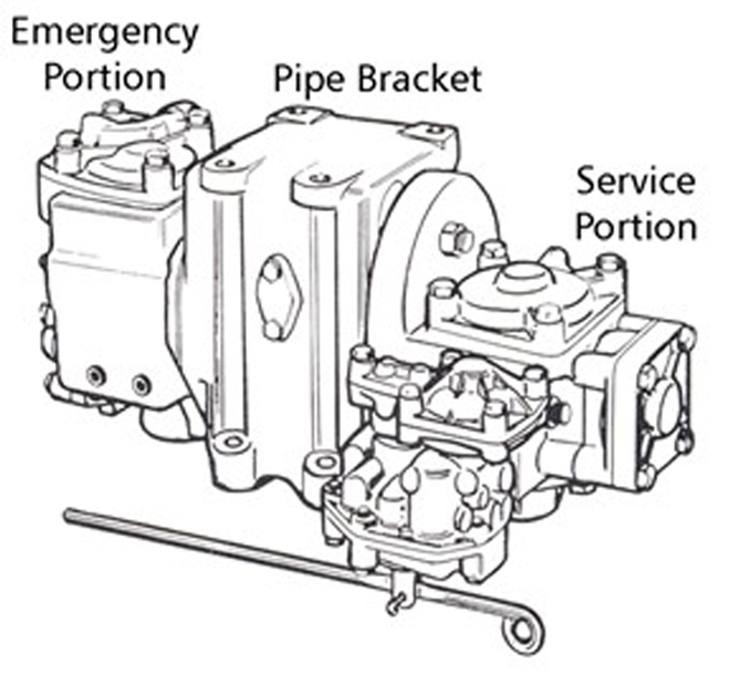
Rail cars are equipped with the following 6 basic air brake components: the brake pipe, a car control valve (CCV), auxiliary and emergency air reservoirs, a brake cylinder, and a retaining valve (Figure A1). A CCV assembly has 2 valve portions, a service portion and an emergency portion, both affixed to a pipe bracket (Figure A2). The CCV has 3 functions: to charge the auxiliary and emergency reservoirs from the brake pipe, to apply the brakes, and to release the brakes.
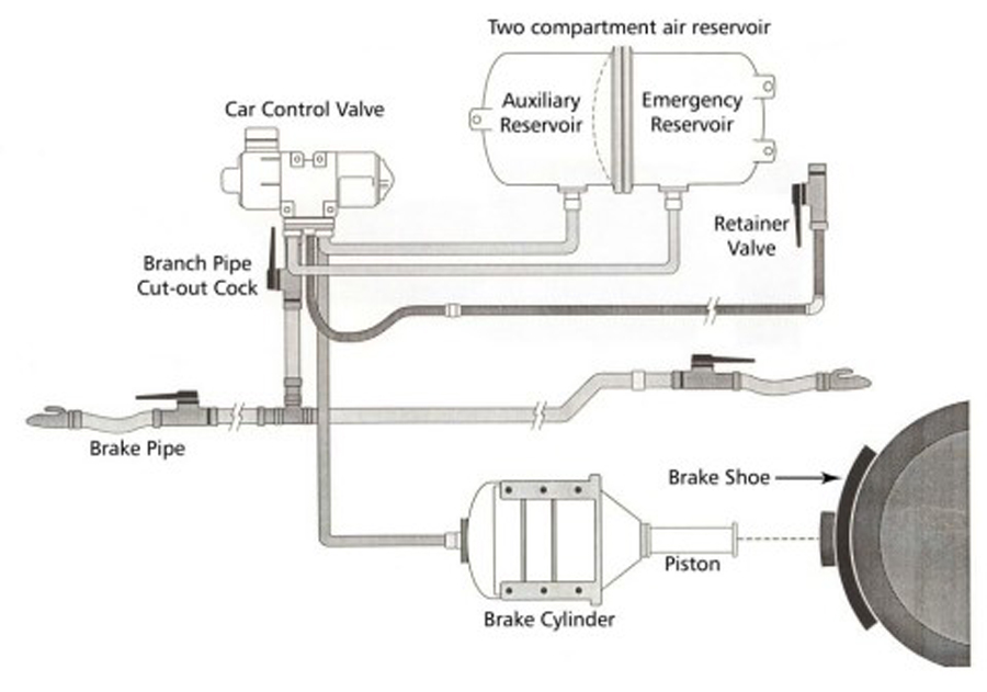
The brake pipe acts to supply compressed air to each car Footnote 3 in the train when the train brakes are released and the system is being charged. The auxiliary reservoir on each car supplies compressed air to the brake cylinder when the brakes are applied and is recharged when the brakes are released. This action is controlled by the CCV reacting to changes in brake pipe pressure.
The brake pipe acts as a signal line to apply or release/recharge the train brakes. The signal is controlled from the automatic brake valve on the lead locomotive by changing the air pressure in the brake pipe. The principle of train air brakes is based on lowering brake pipe pressure to apply the brakes and increasing brake pipe pressure to release the brakes. The train air brake system must be sufficiently charged with compressed air to operate as designed.
When a freight train air brake system is sufficiently charged, the brakes are applied through a controlled reduction in brake pipe pressure. This is called a service reduction. Train brakes can be applied with a minimum application, which is the lightest brake possible, and gradually applied harder in stages until a full service Footnote 4 application is achieved. A service train brake application can be incrementally increased until a full-service brake application is achieved, but it cannot be incrementally released; it can only be fully released.
To apply the train brakes harder than a full-service application requires an emergencyFootnote 5 brake application. This is done by venting the brake pipe air at an uncontrolled rate, allowing the pressure to drop rapidly to 0 psi. Once an emergency brake application is initiated, the drop in brake pipe pressure to 0 psi cannot be stopped.
The CCV on a freight car reacts to an abrupt drop in air pressure by allowing air pressure stored in the emergency reservoir to flow into the brake cylinder. The auxiliary reservoir is also used during an emergency brake application. This causes a faster and higher build-up of brake cylinder pressure, resulting in a harder brake application and a faster stop.
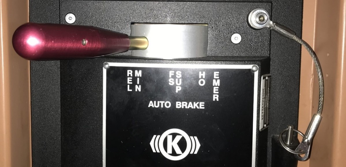
When a normal automatic brake application is required, the locomotive engineer (LE) moves the automatic brake valve handle (Figure A3) to the desired position. This action removes air from the brake pipe at a service rate. As each CCV senses a sufficient reduction in pressure, air flows from the auxiliary reservoir located on each car into that car's brake cylinder, applying the brake shoes to the wheels.
To release the brakes, the LE moves the automatic brake valve handle to the release position. This action allows air to flow from the main reservoir back into the brake pipe, restoring pressure to 90 psi. Sensing an increase in brake pipe air pressure, the CCV on each car allows air to be released from the brake cylinder through its retaining valve, and the brake shoes are removed from the wheels.
To reapply the train brakes after a release requires the brake pipe pressure to again be reduced using the automatic brake valve. Before reapplying the train brakes, the system needs time to recharge. Not allowing sufficient time for the system to recharge may result in the brakes not applying or unintentionally releasing after a short time.
Independent brake system
On a locomotive, the independent brakes are also supplied with air from the main reservoir. Unlike the automatic brake system, the independent brake system is a direct air system. An independent brake valve controls a relay valve that will allow air from the main reservoir to flow into the brake cylinders on the locomotives only.
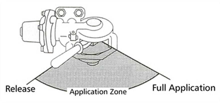
When a full independent brake application is required, the LE moves the independent brake valve handle (Figure A4) to the full application position, and air pressure is supplied to the locomotive brake cylinders. This causes the brake shoes to apply to only the locomotive wheels. Brake cylinder pressure can also be gradually increased or decreased as needed by moving the brake valve handle in the application zone.
To release the independent brakes, the LE moves the independent brake valve handle to the release position. This causes air to be released from the locomotive’s brake cylinders, and the brake shoes are removed from the locomotive wheels. Air pressure in the locomotive brake cylinders is relative to the position of the independent brake valve handle.
Control valves
Each car is equipped with a CCV, which is comprised of a service and an emergency portion. The locomotive air compressors supply air pressure to each freight car through the brake pipe. Brake pipe air pressure comes through the branch pipe tee, then is fed to the CCV through the cut-out cock. The CCV supplies compressed air to the combined reservoir, included on each freight car. The combined reservoir comprises 2 separate sections: an auxiliary reservoir (handling the service brake applications), and an emergency reservoir (mainly supplementing air pressure for an emergency brake application).
When the freight car is fully charged (when the brakes are released), the pressure is equal to 90 psi in the brake pipe, as well as in the auxiliary and emergency reservoirs. During an automatic brake application, brake pipe pressure is reduced, which in turn signals the CCV to apply the brakes by directing air from the auxiliary reservoir into the brake cylinder on the freight car, thus extending the piston, moving the brake beams and setting the brake shoes against the wheels.
During each service brake application, the brake pipe and auxiliary reservoir pressures are equal on the freight car. The CCV monitors any pressure differential between the brake pipe and the auxiliary reservoir. Brakes are released when brake pipe pressure increases by 1.5 to 2 psi above auxiliary reservoir pressure.
When an emergency brake application is initiated for the train, it is usually due to either the LE putting the automatic brake valve handle in emergency, the activation of the conductor’s emergency brake valve or the freight car end hoses coming apart between cars. In either case, the CCVs sense the very rapid discharge of air pressure from brake pipe (brake pipe pressure would drop to 0 psi at a rate of 900-950 feet per second) and directs air pressure from both the auxiliary and emergency reservoirs into the brake cylinder to apply the maximum available braking force and bring the train to a stop.
Finally, when brakes are released, brake cylinder air pressure flows back through the CCV and is exhausted into atmosphere through the retaining valve.
Air flow display
On locomotives equipped with operator display screens, the air flow is displayed in a box identified as “Flow” (Figure A5). The value displayed on the screen indicates the amount of air flow into the brake pipe in cubic feet per minute (CFM). This type of air flow indicator displays 0 when the demand for air falls below 20 CFM.
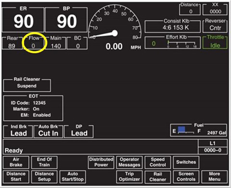
When the train brake system is being charged, the air flow indicator will display a large value, typically higher than 60 CFM. This indicates that there is a high flow of air into the brake pipe. As the system becomes charged, the value displayed will come down, indicating a decrease of flow.
When the value on the air flow indicator stops falling and stabilizes, it indicates that the demand for air is steady and the system is fully charged. The pressure-maintaining feature of the automatic brake valve will compensate for brake pipe leakage. If there is leakage in the brake pipe, the flow value may not reach 0 CFM when the train brake system is fully charged.
Because the air flow indicator measures the rate of air flow to the brake pipe, it can also indicate
- the rate at which a train is being charged or recharged;
- a heavy demand of air in the brake pipe, if a hose has separated or ruptured; or
- a flow of air into the brake pipe as the pressure-maintaining feature of the automatic brake valve compensates for normal leakage.
If the air flow indicator shows an increased air flow while the brakes are applied, it could indicate that
- the brakes are releasing (unintentional release);
- somewhere in the train, a brake pipe coupling hose has come apart;
- somewhere in the train, there is a hose or brake pipe rupture; or
- there is excessive leakage.
Brake pipe pressure maintaining
Pressure maintaining is a feature of the automatic brake valve that allows air to flow into the brake pipe at a controlled rate to overcome normal brake pipe leakage without causing the brakes on the train to release. During service brake applications, it allows the selected brake pipe pressure reduction to be maintained for long periods of time. This feature allows trains to descend long mountain grades with the brakes applied as needed.
Without brake pipe pressure maintaining, leakage will cause the brake pipe pressure to continue falling after the brakes have been applied. Eventually, the brake pipe pressure will drop to 0 psi. Controlling train speed on long descending grades is difficult without brake pipe pressure maintaining.
Pressure maintaining is always functioning when a locomotive is set up to be the lead or controlling remote locomotive on the train. Pressure maintaining is disabled on locomotives set up for trail operation.Footnote 6
Emergency braking
An emergency brake application is the maximum application of a train’s air brakes during which the brake pipe pressure is rapidly reduced to 0, either from a separation of the brake pipe or operator-initiated action. Following an emergency brake application, the air from the auxiliary and emergency reservoirs combine in the brake cylinder. When brake pipe pressure is below 45 psi, a rapid reduction in brake pipe pressure cannot be relied upon to initiate an emergency brake application.
Pressure retaining valves
A pressure retaining valve, commonly called a retainer, is a manually operated valve that can be used to limit the release of air pressure from the brake cylinder after the automatic brake is released. The retainer has 3 settings, which are set by rotating the handle into the appropriate notches:
- The Direct Exhaust (DE) setting, also known as Exhaust (EX), which lets all the air pressure exhaust to the atmosphere. This is the default setting of the retainers on trains.
- The High Pressure (HP) setting, which is designed to nominally hold up to 20 psi of compressed air in the brake cylinder after the car air brake is released. This may help hold the train in a stationary position or control the speed while the air brake system is being recharged. In a situation where the cylinder pressure is less than 20 psi at the time when the air brake is released, the retainer will initially hold whatever pressure existed at that time.
- The Slow Direct (SD) setting, where brake cylinder pressure is fully depleted to atmosphere, but at a much slower rate, when a brake release is commanded.
The HP and SD settings become effective only after releasing the initial brake application. The use of retainers does not provide any additional brake retarding force while the train brakes remain applied. Rather, the retainers are intended to provide a residual amount of braking force after the train brakes (automatic air brakes) are released.
Dynamic brakes
The DB system is designed to be used as a supplementary braking system to the train air brake system. The DB system operates by electrically converting the traction motors of a moving locomotive into electric generators. One of the characteristics of a generator (traction motor) is to resist rotation when it is producing electricity. This resistance is caused by a magnetic field through which the traction motor armature rotates. The movement of the DB handle controls the strength of the magnetic field and the retardation effort. When DB is applied, traction motors are reversed, exercising a drag or braking effect on the train. The rotation of the traction motor armature through the magnetic field generates a current. This current is then sent to the resistor grids that produce heat. Fans mounted on the locomotive roof cool the resister grids and the heat is dissipated to atmosphere.
When only the locomotive DB is used, compressive or “buff” forces are concentrated behind the locomotives. When DB used in combination with train air brake systems, these forces are more evenly distributed throughout the train. DB use on long mountain grades prevents brake shoe friction fade on the locomotives because the locomotive traction motors provide resistance. There is no contact between wheel treads and brake shoes and no frictional heat is generated. When DB is used to supplement the train air brakes, less air brake force is needed, reducing the likelihood of brake shoe friction fade on the train and making it possible to reserve train air brake capacity for use in the event of an emergency.