Associated links (A98H0003)
-
Table of contents
Hydraulic system
Description
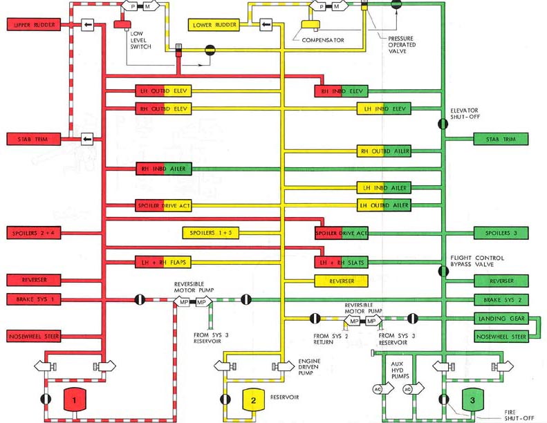
The MD-11 hydraulic system consists of three parallel, continuously pressurized systems that operate between 2 800 and 3 200 psi. All three systems power each of the primary flight controls. Combinations of two of the three systems supply parallel power to the remaining flight controls, nosewheel steering, and wheel brakes.
Hydraulic System 2 shares control over the following hydraulic actuators: the left and right outboard elevator; the left inboard elevator, and the left and right outboard ailerons; the left inboard aileron; the left and right inboard and outboard flaps; and the spoiler drive actuator. Hydraulic System 2 has full control over the Engine 2 thrust reverser, the lower rudder actuator, and spoilers 1 and 5 on both the left and right wings.
Each system is powered by two EDPs. Two electrically driven auxiliary hydraulic pumps, 1 and 2, supply hydraulic pressure to Hydraulic System 3 on the ground or in flight. When electrically powered by the ADG, Auxiliary Pump 1 can provide emergency hydraulic power to Hydraulic System 3. Two RMPs, the 1-3 RMP and the 2-3 RMP, connect Hydraulic System 3 to hydraulic systems 1 and 2. In the event of a loss or shutdown of an engine or a decrease in engine speed, the RMPs can transfer power from an operating system to an inoperative system without transferring any fluid through the openings of their respective shut-off valves. Landing gear hydraulic power is supplied by Hydraulic System 3 or, if Hydraulic System 3 is unavailable, by either RMP.
When the RMP shut-off valves are in the closed position, the RMPs are non-operational. Power to open and close the RMP valves is supplied by the battery bus through CBs B1-599 and B1-598, located in the overhead CB panel at positions A-04 and A-05, respectively. Wires from both CBs are routed through connector P1/R5-394, located in the overhead disconnect panel, and then down the right side of the fuselage behind the right observer's station to the HSC in the avionics compartment.
Two NRMPs, namely the 2-1 NRMP and the 3-2 NRMP, automatically transfer hydraulic power to the rudders and to the stabilizer trim.
Under normal conditions, the HSC controls hydraulic power and operates in the auto mode. The HSC can be switched to manual mode through a push-button selection on the hydraulic system control panel. In the event of a loss of electrical input to the HSC's Channels A and B, the HSC will automatically revert to manual mode. In manual mode, the RMP valves are automatically opened and both RMPs are commanded ON.
The HSC Channel A is powered by the 28 V DC Bus 3 through CB B1-373, located at position S-3 on the upper main CB panel. The HSC Channel B is powered by the 115 V AC Bus 2 through CB B1-372, located at position M-3 on the upper main CB panel. In auto mode, the HSC is designed to configure the hydraulic system based on the phase of flight.
In the landing configuration (i.e., the aircraft is in the air at a barometric-corrected altitude ≤ 17 750 ft., and either the slats or landing gear are extended or the flaps are extended greater than 0 degrees), both RMPs will be commanded ON when the HSC detects a drop in any of the engine speeds below 45% N2. Independent of the engine speed, if the HSC senses a drop in hydraulic pressure below 2 400 psi, it will automatically open the applicable RMP valve and the RMP will be commanded ON. In the event of multiple failures, the HSC is programmed to respond to a loss or shutdown of an engine, or a decrease in engine speed, before responding to a loss of system pressure.
In the cruise configuration, the HSC will not reconfigure the hydraulic system in the event of a loss or shutdown of an engine, or a decrease in engine speed. The RMP valves will remain closed. The HSC receives flap data from the DEUs; according to HSC logic, a loss of flap data will default the flap data to the retract configuration.
Examination
The examination of the upper main CB panel determined that it had not been subjected to heat or fire damage. The wires from both CBs to the HSC were not routed through an area of fire damage. Based on the functioning of other mechanisms (e.g., fans, pumps) dependent on the same power supply, it was determined that the 115 V AC Bus 2 supply for the HSC Channel B was available at the time of impact. As it is likely that at least Channel B was powered at the time of impact, the HSC should have, other than by crew selection, remained in auto mode. As there was no indication of a failure associated with the hydraulic systems, the crew would not have had a need to select the manual mode. The wires from RMP shut-off valve CBs were routed through an area of fire and high heat behind the upper avionics CB panel.
RMP examination
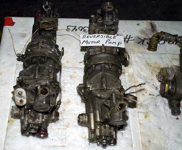
Both of the RMPs were recovered intact and were identified by tag or data plate as PN BYG7001-5511K. Only one RMP had retained a legible serial number: SN 138538A. Since the SNs of the two RMPs could not be found in the aircraft technical documents, the RMPs could not be linked to a specific location (i.e., the 1-3 or the 2-3 position).
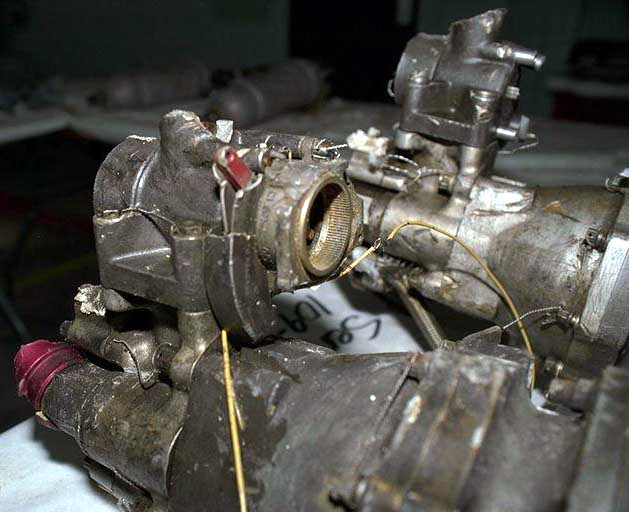
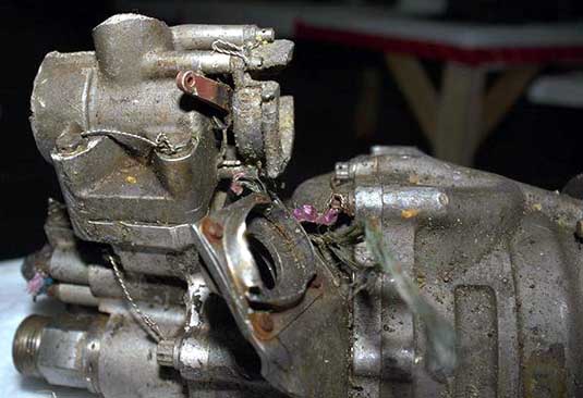
On one RMP (SN 138538A), the two motor-operated shut-off valves were still attached to the pump and the valves were in the normal closed position. The two electric motors had broken off from the valves and were not recovered; the actuator base for one of the motors, however, was still attached to the valve. A portion of the handle cover plate was still in place and the red actuator handle was in the closed position. There was no damage to the handle to indicate that the handle was in other than the normal closed position at the time of impact.
On the other RMP, one motor-operated shut-off valve was still attached to the pump and the other was recovered as a separate unit. Both valves were recovered in the normal closed position. The two electrical motors had broken off from the valves and were not recovered; the actuator base for one of the motors, however, was still attached to the valve. The red actuator handle was in the closed position and there was no damage to the handle to indicate that it was in other than the normal closed position at the time of impact.
RMP determination
As the aircraft was in the landing configuration phase of flight at the time of impact (the flaps were extended) and it had been determined that Engine 2 had shut down prior to impact, the HSC should have opened one or both of the RMP valves. The unexpected closed position of the 1-3 and 2-3 RMP valves may have been caused by one of several scenarios:
- A loss of DEU data to the HSC. In the event of a total loss of DEU data, the HSC will revert to a cruise configuration. A partial loss of DEU data (flap input) will cause the HSC to switch to the flaps retract mode. With a loss of flap data and the slats and landing gear retracted, the HSC will also revert to, or stay in, a cruise configuration. In either case, when the HSC is in the cruise configuration, the RMPs will not be commanded ON with the shutdown of Engine 2, even with a drop in system pressure below 2 400 psi.
- A loss or interruption of electrical power to the RMP valves. This would prevent the RMP valves from opening. The RMP valve's CBs are electrically powered by the battery bus. Since the Engine 2 FUEL switch is also electrically powered by the battery bus and was required for the shutdown of Engine 2, it is unlikely that a loss of battery bus power prevented the RMP valves from opening. A loss of electrical power could be caused by heat or fire, and could either trip the RMP valve CBs, or short or open the wiring from the CBs to the HSC.
- A loss of N2 input to the HSC. With the loss of N2 input, the HSC would not receive data indicating an engine shutdown. In this case, and if the HSC reverts to the land configuration (with the extension of the flaps), the 2-3 RMP valve would only be opened in response to a System 2 pressure drop below 2 400 psi, and the 1-3 RMP would also remain closed. In this scenario, Hydraulic System 2 pressure would have to remain above 2 400 psi after the shutdown of Engine 2.
Determination
An examination of the six hydraulic EDPs found no faults with the pumps that would have affected their operation. With engines 1 and 3 running, hydraulic systems 1 and 3 should have been operational.
With the shutdown of Engine 2 (via the engine FUEL switch), in the land configuration phase of flight and the HSC selection in auto mode, both Engine 2 hydraulic EDPs would have remained in the normal position when the engine speed dropped below 45% N2. If the same conditions had occurred in the cruise configuration, the HSC would have turned off the EDPs.
With Engine 2 shut down (minimal rotation) and the 2-3 RMP not operating, Hydraulic System 2 pressure would only be retained by the Hydraulic System 2 pressure accumulator. Any pressure demand on Hydraulic System 2 (e.g., to the flaps, aileron, elevator, rudder, spoiler, or thrust reverser) would cause Hydraulic System 2 pressure to drop. A drop in Hydraulic System 2 pressure would subsequently cause the 3-2 NRMP to be commanded ON through a pressure operated valve. With the 3-2 NRMP operating, hydraulic pressure to the lower rudder actuator would be maintained. In the event of a shutdown of Engine 2, the loss of hydraulic pressure to the Engine 2 thrust reverser would be of little consequence, as there would not be any thrust supplied by the engine for thrust reverser action once on the ground. The loss of spoilers 1 and 5 would have little effect on lateral control, as the remaining three spoilers on the wing would be operational, the outboard aileron actuators would be active (with flap extension), and spoiler control would not come into effect until the aileron deflection exceeded five units. Control of the primary and secondary flight control actuators, parallel with Hydraulic System 2, would be picked up by the other operating system. In view of the above factors, it was determined that a loss of, or reduction in, Hydraulic System 2 operating pressure would have had little or no adverse effect on aircraft operation.


