Loss of engine power – Collision with terrain
Bearskin Lake Air Service LP (Bearskin Airlines)
Fairchild SA227-AC Metro III, C-FFZN
Red Lake, Ontario
The Transportation Safety Board of Canada (TSB) investigated this occurrence for the purpose of advancing transportation safety. It is not the function of the Board to assign fault or determine civil or criminal liability. This report is not created for use in the context of legal, disciplinary or other proceedings. See Ownership and use of content. Masculine pronouns and position titles may be used to signify all genders to comply with the Canadian Transportation Accident Investigation and Safety Board Act (S.C. 1989, c. 3).
Summary
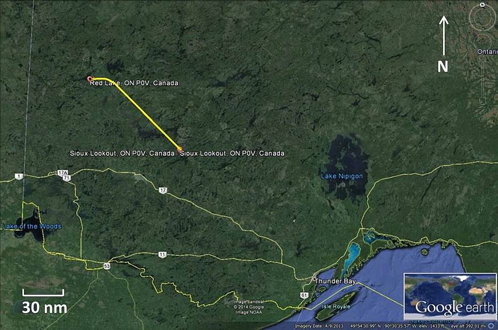
On 10 November 2013, Bearskin Lake Air Service LP flight 311 (Bearskin 311), a Fairchild SA227-AC Metro III (serial number AC 785-B, registration C-FFZN) departed Sioux Lookout, Ontario, with 2 pilots and 5 passengers on an instrument flight rules flight to Red Lake, Ontario. At 1827 Central Standard Time, the crew reported that they were 5 miles from the Red Lake Airport on final approach for Runway 26. Shortly thereafter, the crew declared an emergency. The aircraft struck trees and power lines, and crashed just south of the airfield adjacent to Ontario Highway 125. A post-crash fire ensued which destroyed the aircraft. Two passengers were able to evacuate the aircraft; however, the 2 pilots and remaining 3 passengers sustained fatal injuries. Emergency response units were dispatched to the crash site, and the 2 surviving passengers were transported to a local hospital with non-life-threatening injuries. The 406 MHz emergency locator transmitter did not activate during the accident.
1.0 Factual information
1.1 History of the flight
Bearskin Lake Air Service LP flight 311 (Bearskin 311) was a scheduled flight between Thunder Bay, Ontario, and Winnipeg, Manitoba, with stops in Sioux Lookout, Ontario, and Red Lake, Ontario. On 10 November 2013, the flight from Thunder Bay and the subsequent departure from Sioux Lookout were uneventful. At 1815,Footnote 1 inbound to Red Lake, the crew advised Kenora Flight Service Station (FSS)Footnote 2 of their position (distance and altitude), their estimated time of arrival at the Red Lake Airport, and that they were still working with the Winnipeg Area Control Centre (ACC) for air traffic control. The FSS specialist advised the crew as to the current wind speed and direction, and runway condition. The FSS specialist then asked the crew to report their intended runway for landing, and the crew advised that they would be landing on Runway 26.
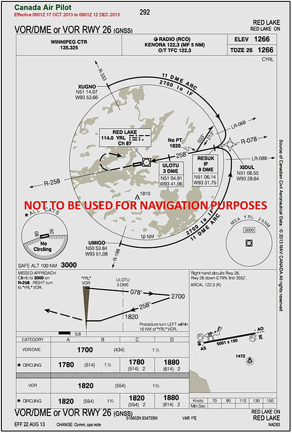
At 1816, Winnipeg ACC cleared Bearskin 311 to the Red Lake Airport for the VOR/DMEFootnote 3 Runway (RWY) 26 approach (Appendix A), and advised the pilots to contact Kenora FSS on 122.2 MHz.
The descent checklist was carried out and, at 1817, the crew advised Kenora FSS that they had been cleared by Winnipeg ACC for an approach to Runway 26 at the Red Lake Airport. Because the crew were expecting to encounter visual conditions prior to landing,Footnote 4 a full approach briefing was not carried out.
The landing checklist was completed and, at 1827:06, the crew advised Kenora FSS that they were 5 nautical miles (nm) on final approach for Runway 26 at the Red Lake Airport. At 1828, at approximately 500 feet above ground level (agl) and approximately 1.4 nm from the runway, the crew noted an aircraft malfunction but did not immediately identify the nature of it. Maximum power was applied to one or both engines, and the landing gear was initially selected up and then re-selected down before it could fully retract. The crew declared an emergency with Kenora FSS and unsuccessfully attempted to initiate a climb. Shortly afterwards, the aircraft veered and rolled to the left, descended, and struck trees with its left wing. The aircraft continued through the trees and struck a series of hydro lines that ran parallel to Ontario Highway 125, before coming to rest in a wooded area adjacent to the highway.
1.2 Injuries to persons
| Crew | Passengers | Others | Total | |
|---|---|---|---|---|
| Fatal | 2 | 3 | – | 5 |
| Serious | – | 1 | – | 1 |
| Minor/None | – | 1 | – | 1 |
| Total | 2 | 5 | – | 7 |
1.3 Damage to aircraft
The aircraft was destroyed by impact forces and a post-crash fire. The aircraft's emergency locater transmitter (ELT) was destroyed by impact forces and did not activate.
1.4 Other damage
The aircraft damaged trees, 6 hydro lines, and 1 communication cable which paralleled Ontario Highway 125 leading to the airport. The hydro lines and communication cable were stretched and broken, and 4 hydro poles were snapped off. The breakage of the hydro lines led to a loss of power and communications to numerous houses and businesses in the community and on the airport property.
The crash site was contained in a small forested area and was assessed as having minimal environmental impact. The aircraft was not carrying hazardous cargo. Fuel and oil were burnt off in the post-crash fire.
1.5 Flight crew information
There were 2 pilots operating C-FFZN. The captain was the pilot flying (PF) and was seated in the left pilot's seat. The captain held a Canadian airline transport pilot licence (ATPL) which was endorsed for the Swearingen SW4 and SW5Footnote 5 aircraft types. He had been employed with the company since 2009. The captain's most recent pilot proficiency check (PPC) was completed on 01 June 2013, and a company line check was completed on 08 October 2013; both were successful.
The first officer (FO) was the pilot monitoring (PM) and was seated in the right pilot's seat. The FO held a Canadian commercial pilot licence (CPL) which was endorsed for SW4 and SW5 aircraft types. He had been employed with the company since July 2012. The FO's most recent PPC was completed on 13 July 2012, and a company line check was completed on 03 August 2012; both were successful.
| Captain | First officer | |
|---|---|---|
| Pilot licence | Airline transport pilot licence (ATPL) | Commercial pilot licence (CPL) |
| Medical expiry date | 01 July 2014 | 01 March 2014 |
| Total flying hours | 5150 | 2200 |
| Flight hours on type | 3550 | 1060 |
| Flight hours: last 7 days | 18.9 | 9 |
| Flight hours: last 30 days | 97 | 49 |
| Flight hours: last 90 days | 251 | 187 |
| Flight hours on type: last 90 days | 251 | 187 |
| Hours on duty prior to occurrence | 8 | 8 |
| Hours off duty prior to work period | 96 | 11 |
Records indicate that the flight crew were certified and qualified for the flight in accordance with existing regulations. A review of all available information indicated that the crew were adequately rested.
1.6 Aircraft information
1.6.1 General
| Manufacturer | Fairchild |
|---|---|
| Type, model, and registration | SA227-AC Metro III C-FFZN |
| Year of manufacture | 1991 |
| Serial number | AC-785-B |
| Certificate of airworthiness issue date | 25 March 1992 |
| Total airframe time | 35 474.9 hours |
| Engine type (number of engines) | Honeywell TPE331-11U-612G (2) |
| Propeller type (number of propellers) | McCauley 4HFR34C652-K (2) |
| Maximum allowable take-off weight | 7257 kg |
| Recommended fuel types | Jet A, Jet A-1, Jet B |
| Fuel type used | Jet A |
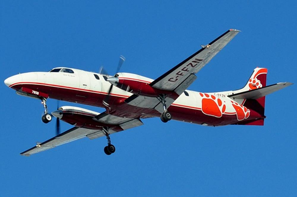
The Metro SA227 is a low-wing pressurized turboprop aircraft configured to carry 18 to 19 passengers (Photo 1).
Records indicate that the aircraft was certified, equipped, and maintained in accordance with existing regulations and approved procedures. There were no reported outstanding defects with the aircraft.
1.6.2 Engines
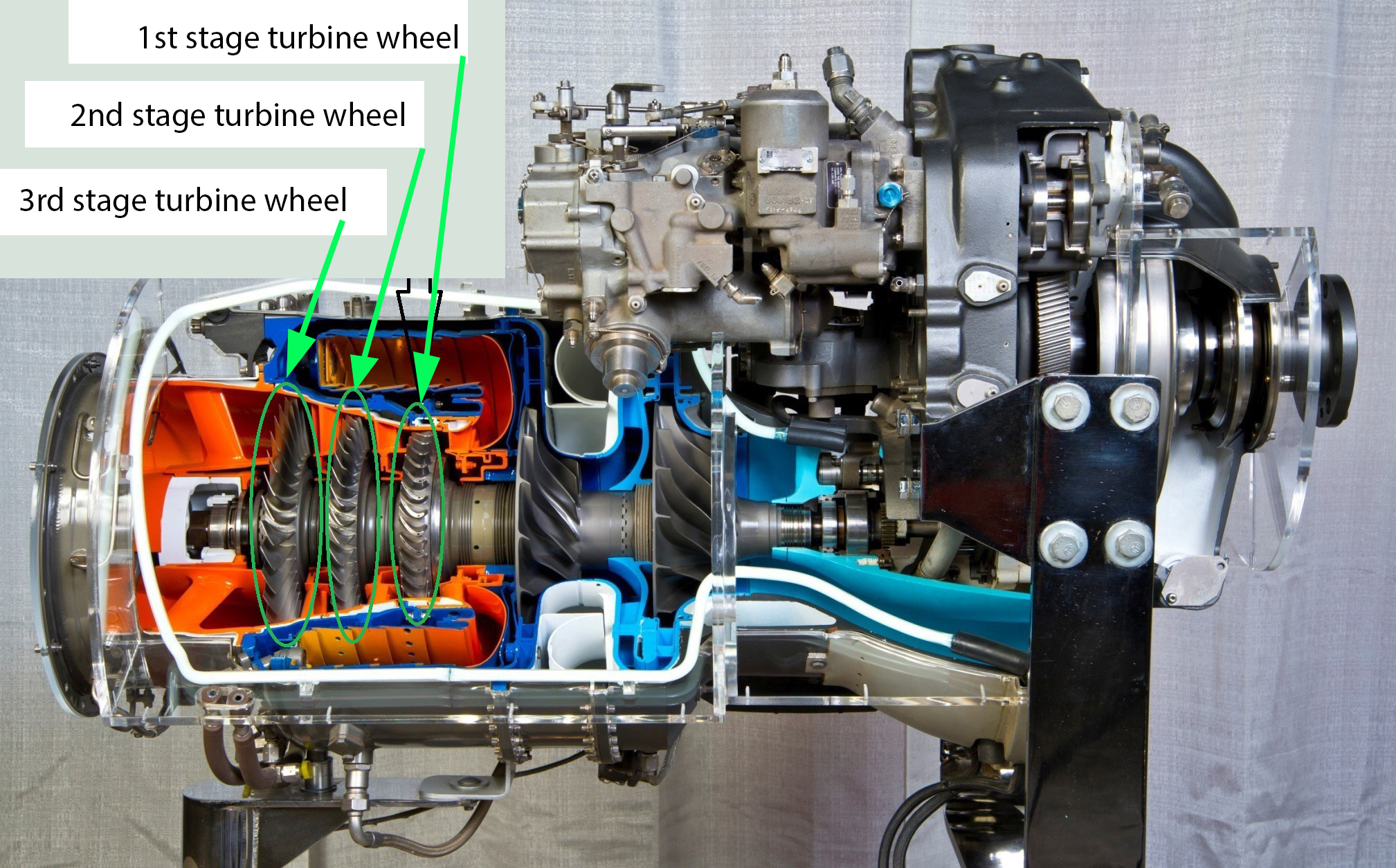
The aircraft is powered by 2 Honeywell TPE331-11U-612G turboprop engines. Each engine comprises a single spool with a 2-stage centrifugal compressor driven by a 3-stage axial-flow turbine, a single reverse-flow annular combustor, and an integral reduction gearbox that drives the aircraft propeller. The engine has a maximum continuous rating of 1000 shaft horsepower. The engine is designed to run at a constant speed (N1), and each engine is controlled by use of an engine power lever and an engine speed lever mounted side-by-side on the throttle quadrant in the cockpit. N1 speed is directly proportional to propeller speed (rpm) and displayed in the cockpit by a percent rpm gauge. Engine power, or torque, is displayed in the cockpit by a percent torque gauge. The gauges are located on the instrument panel, left of the throttle quadrant.
The engine power lever connects to the propeller pitch control and the manual fuel valve. The engine speed lever connects to the propeller governor and to the underspeed fuel governor.
The power lever controls the engine power by positioning the manual fuel valve in the fuel control unit (FCU), which varies fuel flow (power) in direct response to the manual positioning of the power lever. There are 2 modes of operation dictated by the power lever position. When the engine power lever is forward of the flight idle stop, the engine is in the propeller governing mode; this mode maintains a constant rpm by varying the propeller blade angle in direct response to movement of the power lever, which adjusts the fuel flow.
When the engine power lever is aft of the flight idle stop, the engine is in beta mode.Footnote 6 In beta mode, the engine power lever varies the engine load by changing the propeller blade angle through the propeller pitch control. The engine rpm is maintained, in response to the load, by varying the fuel flow through the underspeed fuel governor in the FCU.
The engine speed lever incorporates a high- and low-rpm lever position that enables the flight crew to reduce the engine rpm for noise reduction and fuel economy. The rpm selected by the speed lever depends on the positioning of the power lever in either of its 2 modes of operation. With the power lever forward of the flight idle stop in the propeller governing mode, the speed lever high position sets the propeller governor rpm at 100% for takeoff and landing. During cruise, the rpm is set by the crew to 97% with the speed levers as per the aircraft flight manual (AFM). With the power lever aft of the flight idle stop, in beta mode for ground operations, the speed lever low and high positions set the rpm range of the underspeed fuel governor between 71% and 97%.
The engines were maintained under a continuous airworthiness maintenance (CAM) inspection schedule that requires an engine overhaul at 7000 hours with a mid-life hot section inspection at 3500 hours. The serviceability of the internal engine components is controlled by inspection criteria, time and/or life-cycle limits. One of the components to which this applies is fuel atomizer nozzles. Because blocked or damaged nozzles can affect flow rates and patterns, which in turn can create a condition known as streaking,Footnote 7 they are removed and checked for damage and cleanliness at 450-hour intervals. Information supplied by the manufacturer suggests that it would be possible to boroscope-inspect other internal engine components, such as stator guide vanes and first-stage turbine blades, at the time the fuel nozzles are removed. Currently, there is no requirement to inspect these other components in conjunction with the fuel nozzle inspection, unless “fuel nozzle plugging or adverse streaking is suspected.”Footnote 8
The left engine was installed on the accident aircraft on 15 May 2011. At the time of the occurrence, the engine had accumulated 32 267 hours time since new (TSN) and 2948 hours since its last major overhaul CAM inspection.
The right engine was installed on the accident aircraft on 04 August 2012. At the time of the occurrence, the engine had accumulated 18 526 hours TSN and 1029 hours since its last major overhaul CAM inspection.
1.6.3 Propellers
The aircraft is equipped with 2 McCauley 4HFR34C652-K four-bladed, full-feathering, constant-speed, reversing-pitch aluminium propellers. Springs and counterweights move the blades towards high pitch to decrease rpm, and the propeller governor boosts engine oil pressure to move the blades towards low pitch to increase rpm. The governor oil pressure is transferred through the propeller pitch control and the beta tube into the propeller hub to move the piston and blades. The blade travel angle is from −5° for full reverse to +88.5° for full feather, with physical stops at those locations. A variable low pitch stop provides a hydraulic lock between the beta tube and propeller pitch control, and controls the blade angle on a varying scale from 15° at the flight idle stop position to 21.5° at the 90% power lever position. The propeller has an internal start-lock flyweight arrangement which locks the propeller servo piston at a 6° blade-angle setting during engine shutdown, which facilitates engine restart.
Feathering is provided for by a crew-operated engine stop and feather knob mounted on the centre pedestal in the cockpit. Pulling the knob stops the fuel to the engine and then pushes the high-pressure governed oil through a feathering valve. This allows the internal propeller-feathering spring and the external counterweights to move the propeller blades into the feather position.
1.6.4 Negative torque sensing system
The negative torque sensing (NTS) system is designed to reduce propeller drag forces on the aircraft which cause yaw if an engine fails during flight. The NTS system senses negative torque on the engine if the propeller is windmilling and driving the engine. The NTS system cycles the propeller blades to provide momentary protection from a windmilling propeller and in-flight negative torque protection for the engine. When negative torque is detected,, the NTS valve directs oil pressure to the feathering valve, which increases the blade angle to reduce the unwanted propeller drag. The NTS system is calibrated by 3 torque load assemblies to sense a negative torque of −3% to −4% before activating.
The investigation revealed that the descriptions of the NTS system in several SA227/SA226 training manuals were such that pilots could interpret them to mean that the system would automatically provide anti-drag protection in the event of an engine failure or power loss.Footnote 9 The NTS system does provide partial anti-drag protection if negative torque is sensed, but not to the extent that is provided by a fully feathered propeller. An autofeather system completely feathers an affected propeller permanently to provide anti-drag protection in the event of a loss of propeller thrust associated with an engine failure.
Misinterpretation by flight crews of the purpose or function of the NTS system in the event of an engine power loss may lead them to believe that the NTS system will always activate in the event of a power loss or that NTS activation alone will provide adequate anti-drag protection. As a result, flight crews may not initiate the Engine Failures In Flight checklist in a timely manner. If the NTS system activates due to an engine failure, standard operating procedures (SOPs) require flight crews to feather the affected propeller, as directed in the AFM, to eliminate propeller drag.
1.6.5 Enhanced ground proximity warning system
The aircraft was equipped with a Honeywell Mark VI enhanced ground proximity warning system (EGPWS). The EGPWS is a Class A terrain avoidance warning system (TAWS) that provides protection against controlled flight into terrain (CFIT). The system issues warnings to flight crews that include excessive rate of descent, terrain closure rate, excessive altitude loss after takeoff or missed approach procedure, insufficient terrain clearance, descent below glideslope, and excessive bank angle. It also provides audio callouts at various radio altitudes and descent height minimums during approach. During the approach prior to the occurrence, the unit produced no warnings, although it did provide a standard radar altimeter callout at 500 feet agl.
1.7 Meteorological information
The 1800 aviation routine weather report (METAR) for the Red Lake Airport was wind 300° true (T) at 14 knots gusting to 22 knots, visibility 10 statute miles (sm) in light snow and drifting snow, ceiling overcast at 1800 feet agl, temperature −10°C, dew point −13°C, altimeter setting 30.08 inches of mercury, remarks: cloud opacity 8 oktas.Footnote 10 A special weather observation (SPECI) taken at the Red Lake Airport 15 minutes after the occurrence was wind 320°T at 10 knots, visibility 8 sm in light snow and drifting snow, scattered cloud at 2000 feet agl, remarks: cloud opacity 3 oktas. The wind observed by ground personnel at the Red Lake Airport at the time of the occurrence was similar to that reported in the 1800 METAR and was described as quite gusty.
1.8 Aids to navigation
Navigation to and around the Red Lake Airport is provided by a VOR (very high frequency omnidirectional range) on a frequency of 114.0 MHz and an NDB (non-directional beacon) on a frequency of 218 kHz. Both navigational aids were operating normally at the time of the occurrence. There are 3 published instrument approach procedures to the Red Lake Airport. At the time of the occurrence, the crew of C-FFZN was conducting the global positioning system (GPS) overlay VOR/DME or VOR RWY 26 (GNSS) approach (Appendix A).
1.9 Communications
During the approach, the crew of Bearskin 311 declared an emergency with Kenora FSS at 1828. They did not state the nature of the emergency. At 1829, the crew transmitted the word Mayday 3 times. Upon reception of the emergency transmission, the Kenora FSS specialist contacted police and emergency response personnel. With the aid of the Red Lake Airport personnel, the police and emergency response personnel were directed to the approximate location of the accident site.
1.10 Aerodrome information
The Red Lake Airport is a Transport Canada-certified airport with 1 asphalt runway (08/26) that is 5000 feet long by 150 feet wide. A review of recent airport equipment inspections revealed no unserviceable equipment at the time of the occurrence.
1.11 Flight recorders
The aircraft was equipped with a solid state L3 Communications model FA2100 cockpit voice recorder (CVR) and a solid state Fairchild model F1000 flight data recorder (FDR). The CVR records 2 hours and the FDR records 25 hours of data before the data are overwritten with new information.
The CVR and FDR were sent to the TSB Laboratory, and the information stored on those devices was successfully retrieved. The data provided important details about the occurrence flight and were instrumental in the investigation.
Table 4 outlines some of the pertinent information obtained from the FDR.
| Time | Event | Left engine torque | Left engine N1 speed |
Right engine torque | Right engine N1 speed |
Airspeed (knots) | Roll |
|---|---|---|---|---|---|---|---|
| 18:28:17 | Normal approach | 22% | 98.5% | 22% | 99% | 128 | |
| 18:28:18 | Left engine malfunction | −1% | 96% | 38% | 102% | 127 | |
| Crew power changes | |||||||
| 18:28:21 | Maximum power set | 0% | 97% | 102% | 101% | 125 | |
| 18:28:42 | 1st power reduction | −2% | 98% | 91% | 99% | 10° Left | |
| 18:28:53 | 2nd power reduction | −1% | 96% | 54% | 99% | 102 | 15° Left |
| 18:29:01 | Power increased | 0% | 96% | 98% | 103% | 108 | 41° Left |
The FDR data showed that the left engine suffered a drop in torque approximately 56 seconds before impact and that the engine was running at impact, but at very low power. The FDR data showed that the right engine was operating normally and producing full power when commanded. The FDR data also showed that the right engine power was rapidly reduced before impact.
1.12 Wreckage and impact information
1.12.1 General
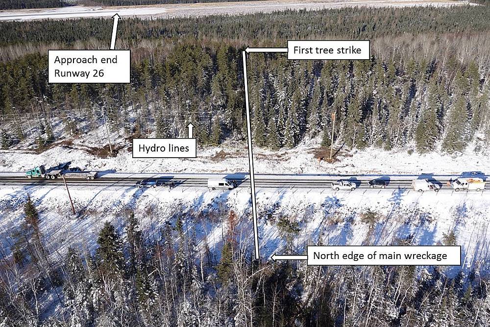
The aircraft struck trees while in a steep left-wing-low attitude approximately 2300 feet south of the approach end of Runway 26 (Photo 2).
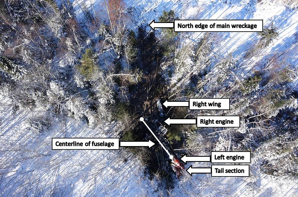
The outboard 8-foot section of the left wing was torn off, and the aircraft travelled approximately 375 feet before striking hydro lines that paralleled Ontario Highway 125 leading to the airport. The aircraft contacted the south edge of the highway road bed, at which point the left engine and propeller separated from the aircraft. The aircraft cartwheeled and slid tail first coming to rest 150 feet from the highway in an area of trees. The left engine came to rest underneath the tail section. The right engine and wing broke off during the impact sequence. Both propellers had detached from their respective engines. The front of the aircraft forward of the wing main spar was severely crushed and deformed; the cabin area aft of the wing trailing edge remained largely intact. Most of the aircraft was consumed by the post-crash fire (Photo 3).
Continuity of the flight control systems was established to the extent possible considering the fire damage. The landing gear and flaps were determined to be in their full down positions. The ailerons were trimmed neutral, the rudder was trimmed 5° nose left, and the horizontal stabilizers were trimmed nose up within the green takeoff range on the stabilizer trim indicator.
The EGPWS and annunciator panel were recovered and sent to the TSB Laboratory in Ottawa for examination and information recovery. The left-hand oil pressure light was the only bulb illuminated at impact. There was no recoverable information from the EGPWS due to damage.
Both engines and propellers were recovered for further examination.
1.12.2 Propeller examinations
The 2 McCauley propellers, left-hand (LH) S/N 080077 and right-hand (RH) S/N 080222, were transported from the accident site to the propeller manufacturing facility in Wichita, Kansas, for examination. A TSB investigator was in attendance for the examination. The propellers were examined for condition, including failures and/or malfunctions, position of the propeller blades at impact, and an estimate of engine power or rotational energy. The conclusions were based on a variety of observations:
- Both propellers had sudden-failure damage that is typically associated with impact forces and gross component damage. The investigation found no evidence of any type of fatigue failure.
- Both the LH and RH propellers were recovered with the spinner shells crushed and formed around the hub and blades by the impact sequence. Both the LH and RH spinners formed around the blade counterweights in a position consistent with the low pitch / start lock blade angle (approximately 6° blade reference angle) at impact.
- Both the LH and RH propeller hubs had marks from blade counterweight impacts during the accident sequence. The position of these marks indicated a propeller blade angle of approximately low pitch / start lock position at impact.
- The LH and RH propeller pitch change systems were relatively undamaged, and the piston positions of both propellers indicated blade angles of approximately low pitch / start lock position at impact.
- The LH and RH propeller internal start lock mechanisms were not engaged.
- Blade bending, twisting, and overall propeller assembly damage on both the LH and RH propellers is typical of that associated with some mid-level rotational energy absorption (higher than windmilling but less than full power) at impact.
1.13 Medical and pathological information
A post-mortem examination was conducted. Along with the toxicology report, the post-mortem showed no indication of any physiological conditions or substances that would have impaired the crew's ability to conduct the flight.
1.14 Fire
Both wing fuel tanks were ruptured during the impact sequence, and a post-crash fire ensued which consumed most of the aircraft.
1.15 Survival aspects
The initial contact with the trees and hydro lines arrested the aircraft's speed and descent rate, and attenuated the force of the impact with the edge of the roadway. The aircraft cartwheeled down a slope which further reduced the force of the impact to the occupants in the rear of the aircraft. When the aircraft came to rest, the fuselage was broken in half forward of the overwing emergency exits and the front half of the aircraft was on fire. The passenger in the left rear seat was able to open the left emergency overwing exit and help extract a passenger who was jammed between the seats near the exit row. The other occupants did not survive the impact. One of the 2 surviving passengers called 9-1-1 with a cell phone, and local Ontario Provincial Police and fire and emergency services responded. The surviving passengers were transported to a local hospital.
1.16 Tests and research
1.16.1 Engine examinations
1.16.1.1 General
The 2 Honeywell TPE331-11U-612G engines, LH S/N P-44121C and RH S/N P44-583C, were transported from the accident site to the TSB regional wreckage examination facility in Winnipeg, and then to the engine manufacturing facility in Phoenix, Arizona, for examination.
1.16.1.2 Left engine
The examination found that the LH engine had severe impact damage to the nose gear case area. The gear case was removed and all damage that it had sustained was considered impact-related. The gear box chip detector was clean. The high-speed pinion shaft, starter generator shaft, and FCU drive shaft were intact and not sheared. Of the 3 torque load arms used to preload the internal torque ring for operation of the NTS system, 2 were either damaged or missing. The installation torque setting on the 1 remaining torque arm was checked and found to be within the prescribed range. The NTS valve was checked for internal valve movement and found to be in the normal range. The NTS orifice pack was removed and found to be unrestricted and free of debris. The NTS valve was removed and tested, and no faults were found. The FCU main fuel screen, internal finger screen, and flow divider screen were checked and found to be clean and free of debris. The FCU fuel pump drive shaft and the stacked FCU shaft were intact. The flow divider was removed and tested, and found free of faults that would have affected engine performance.
The combustion chamber was removed and found to be caked with burnt organic matter from tree ingestion. The organic matter had clogged the bleed air cooling passages in the combustion can, fuel nozzles, and first-stage stator (nozzle) assembly. The burnt organic matter was considered a good indicator that the engine was running at impact. The compressor was disassembled, and blade damage and diffuser rub were noted indicating rotational energy at impact.
The fuel nozzles were removed, and a computerized tomography (CT) scan was carried out before attempting to remove the organic debris that had been impacted into the secondary bleed airblast passages. The CT scan found that the number 9 fuel nozzle had a crack between the primary and secondary fuel flow channels. Metallurgical examination of the crack found that fatigue had progressed approximately two-thirds of the circumference of the secondary fuel tube and had progressed through the full diameter of the tube. The crack in the tube would have allowed cross flow between the primary and secondary flows which could have affected atomization of the fuel during start-up. A gentle cleaning of the debris was attempted on one of the nozzles; however, the debris was caked on and could not be removed. Damage to fuel nozzle number 9 prevented flow-checking the nozzle. However, alternate flow rate testing on exemplar fuel nozzles indicated that cross flow leakeage was possible (with damage similar to the crack in the occurrence aircraft's number 9 fuel nozzle), during start-up and when the engine was idling. The burnt debris prevented the testing of the spray angle and quality.
The turbine section was disassembled, and the turbine bearing support housing was found cracked around the bolt-hole locations. The support housing was examined by the TSB Laboratory, and the cracking was determined to be overload in nature and a result of the impact forces. The second- and third-stage turbine wheels had moderate to severe tip damage from upstream debris being expelled past the wheels.
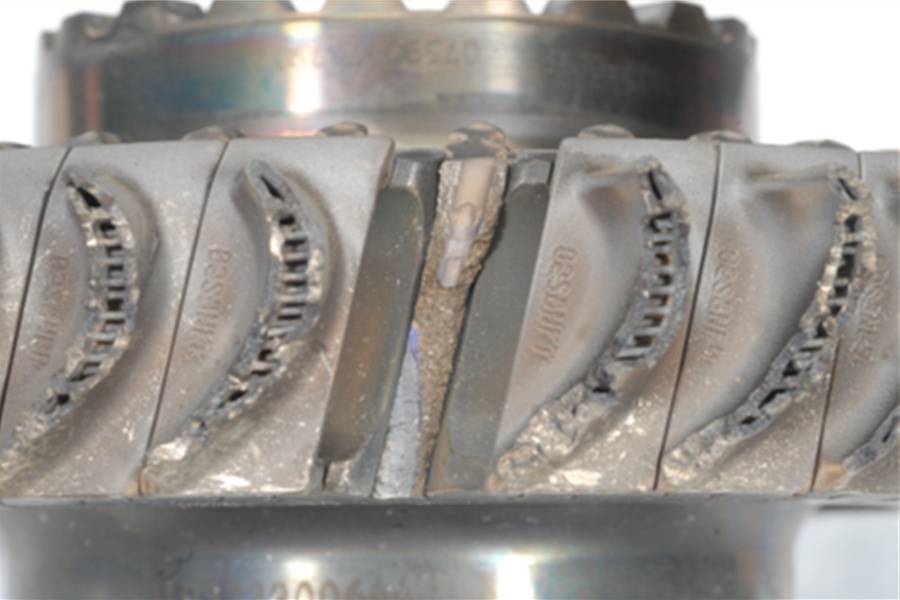
The first-stage wheel (Photo 4, Photo 5 and Photo 6) was stripped of all blades down to the blade roots with 1 blade failing at the fir treeFootnote 11 blade root area. The area of failure exhibited a distinct fatigue zone near the trailing edge of the blade and was sent to the TSB Laboratory for metallurgical examination. The examination concluded that the blade failure occurred as a result of high-cycle fatigue in an area of high porosity.
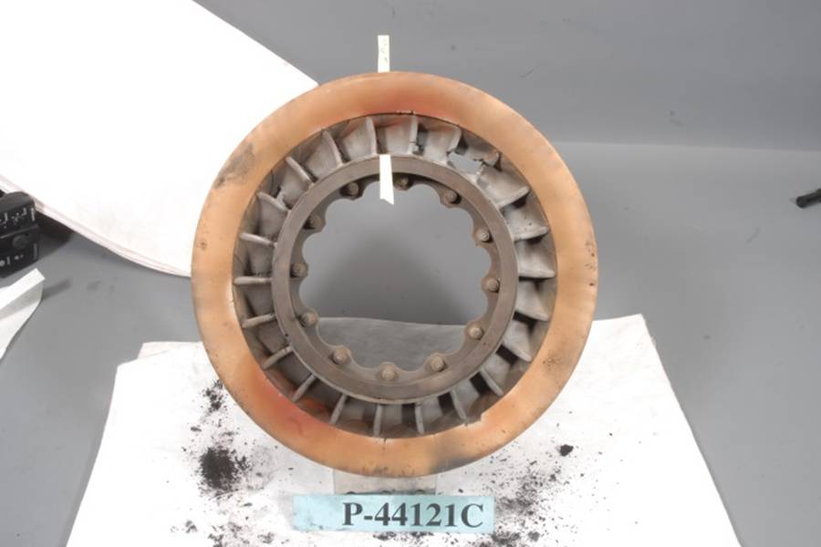
The first-stage stator (nozzle) assembly (Photo 7 and Photo 8) was examined and burn-through was noted on one of the stationary nozzle vanes. Several other nozzle vanes showed areas of cracking, material loss and heat distress. The stationary first-stage stator assembly is upstream of the first-stage turbine wheel and directs hot combustion air onto the rotating turbine wheel.
The engine manufacturer indicated that there had been previous incidents of first-stage turbine wheel blade failures and stator burn-through. At times, the 2 failures occur in conjunction with one another and at other times only the turbine blade fails. The turbine blade failures have been attributed in some instances to porosity issues in the casting process and/or fatigue issues caused by excessive turbine distress due to stator vane burn-through. A burn-through in the stator vane will produce a vibrational response (one per revolution) in the blades that can lead to the blades separating in a high-cycle fatigue mode. Stator vane burn-through has been attributed to streaking fuel nozzles or the blockage of the first-stage stator cooling tubes which could cause hot spots on the stator vane.
As part of the investigation, the engine manufacturer conducted a root and contributing cause analysis of the turbine blade separation. The analysis focused on the fatigue life capability, mean stress/loading, alternating stress/loading, mechanical vibratory characteristics, and material characteristics.
The fatigue life capability was examined using the Goodman diagramFootnote 12 to illustrate the fatigue life of the MAR-M247 directionally solidified superalloyFootnote 13 blade material. Recently available updated and advanced modeling was used, and a high-stress region was noted in the outer diameter of the blade's fir tree lobe area that fell outside of the desired area of the Goodman diagram. This calculated analysis indicated a shortcoming in the fatigue capability and robustness of the blade material, and was assessed as a contributing cause.
The mean stress/loading analysis was accomplished by examining the adjoining blade platforms for contact along the axial length. Contact of the blade platforms at transient engine accelerations could cause a stiffening of the blade boundary, and alter the blade loading and natural operating frequency. Some blade platform contact was noted, and finite element modeling indicated a slight increase in the mean stress in the blade's fir tree region; however, it was minor in nature and assessed as a minor contributing cause to the blade failure.
The alternating stress/loading analysis looked at the fractured rear turbine support housing, which could allow the power rotating group to have an orbiting motion, along with fuel flow disturbances and stator burn-through, which could create a lower engine order excitation. The failure of the rear turbine support housing was determined to be overload in nature and not a factor in the occurrence. The cracked number 9 fuel nozzle could not be tested and was excluded from this analyis. Testing of exemplar fuel nozzles indicated cross flow leakeage could occur during engine start-up and during idle operations. However, it could not be determined if this condition had actually occurred in the occurrence aircraft's engine.
Engineering experience has shown that air gusts through the failed (burnt-through) stator portion will increase the alternating stress experienced by the blade, and stator burn-through was assessed as a contributing cause. Research indicates that stator burn-through could be caused by hot starts and over-temperature operation, a blocked stator vane cooling flow, or streaking fuel nozzles. No evidence of a hot start, an over-temperature condition, or a pre-blocked stator vane cooling flow was found. The cracked fuel nozzle could not be tested for flow or spray pattern, and it could not be determined if it had produced a streaking effect on the burnt-through stator vane. A swirl pattern analysis of the internal engine airflow, taking into account the installed position of the cracked nozzle in relation to the installed position of the burnt-through stator vane, showed that the operation of a fuel nozzle in this position could have had a direct effect on the burnt-through stator vane.
Examination of the mechanical vibratory characteristics looked at the seal plate pressure against the leading edge of the first-stage turbine blade platform as a means of creating dampening. It was determined that sufficient blade pinch existed and that mechanical vibratory characteristics were not a factor.
The material blade characteristics were examined for defects that could lower the fatigue capabilities of the turbine blade material. The failed blade microstructure was normal; however, porosity was measured to be higher than the allowable material requirements in the areas associated with the crack initiation. Porosity of the material can create a favourable location for a crack to initiate if stressors are present, and was assessed as a contributing cause.
In summary, the manufacturer's contributing cause analysis determined that the first-stage turbine wheel failed because of high-cycle fatigue which was the result of the following factors:
- Substandard porosity of the turbine blade material which resulted in inadequate fatigue capability and the creation a favourable location for crack initiation.
- A minor increase in the mean stress in the blade fir tree region due to blade platform contact.
- Stator burn-through which resulted in an uneven vibration on the first-stage turbine wheel assembly and heat stress on the turbine blades.
The examination of the engine concluded that, in this occurrence, the failure of the first-stage turbine blade by itself would not have caused the engine to lose all power. However, its failure caused damage to the remaining turbine blades, which reduced the efficiency of the engine and would have greatly reduced the power output of the engine to drive the propeller.
The investigation revealed discrepancies between the manufacturer's maintenance and fuel nozzle overhaul manuals. Consequently, examining fuel nozzles as per the maintenance manual might result in a nozzle being deemed unserviceable, whereas testing as per the overhaul manual might result in the same nozzle being evaluated as serviceable. The number 9 fuel nozzle in the occurrence aircraft's left engine had at one time been removed, tested and found unserviceable. It was then sent out for overhaul, tested according to the instructions in the fuel nozzle overhaul manual, found serviceable, and then reinstalled in the left engine.
1.16.1.3 Right engine
The complete disassembly of the RH engine showed no internal faults that would have affected engine performance. The FCU fuel pump and drive shafts were intact, and all fuel and oil filters were clean. Burnt organic matter was found in the compressor and combustor areas from ingestion of the material during impact, indicating that the engine was running.
1.16.1.4 Flight test information
A test flight was conducted with a similarly equipped company SA227 aircraft. When the aircraft was configured and placed in a similar profile to the occurrence aircraft, the aircraft was controllable but unstable.Footnote 14 At 104 knots indicated airspeed (KIAS), full control inputs on all axis was required, indicating that the minimum control speed (VMC) in the landing configuration was approximately 104 KIAS. VMC represents the minimum speed at which the aircraft is directionally controllable with the critical engineFootnote 15 inoperative. (A more complete description of this phenomenon is found in sub-section 1.18.2). Below VMC, a pilot may not be able to control the aircraft.
1.16.2 TSB laboratory reports
The TSB completed the following laboratory reports in support of this investigation:
- LP009/2014 – Turbine Engine Examination
- LP217/2013 – FDR [flight data recorder] Download and Analysis
- LP234/2013 – EGPWS [enhanced ground proximity warning system] and Annunciator Analysis
1.17 Organizational and management information
1.17.1 General
The company holds a Canadian Aviation Regulations (CARs) Subpart 704 commercial air services, air operator certificate for commuter aircraft. At the time of the occurrence, the company had 4 major bases of operation, located in Winnipeg, Manitoba; Sioux Lookout, Ontario; Thunder Bay, Ontario; and Kitchener, Ontario. The main base of operations was in Thunder Bay, which was equipped with a heavy maintenance facility and an engine overhaul shop. At the time of the occurrence, the company operated 18 Fairchild Metro SA227 aircraft.
1.17.2 Safety management system / quality assurance programs
Transport Canada has not yet implemented a requirement for CAR Subpart 704 operators to have a safety management system (SMS) in place. In anticipation of this requirement and to promote a healthy safety culture, the company has developed an SMS in conjunction with its quality assurance (QA) program. Both the SMS and QA departments are staffed with a Bearskin Airlines manager. In addition, the QA department has a QA committee. The SMS manager oversees the safety reporting system for the entire company, and the QA manager handles internal audit and non-conformance findings. The company uses a Q-Pulse software system to manage its safety, quality, and risk assessment systems. The company has quarterly meetings with the SMS and QA managers, along with the accountable executive, senior management, base managers, person responsible for maintenance (PRM), operational manager, and chief pilot to discuss safety items and ongoing issues of concern.
1.17.3 Crew training
Pilots at Bearskin Airlines receive the following aircraft type-specific (SA227) training:
First officer initial training:
- 4 hours cockpit procedures trainer (CPT)
- 5 to 6 hours aircraft training
- pilot proficiency check (PPC)
- 20 to 30 hours aircraft line indoctrination
Captain upgrade training:
- 2 hours CPT
- 2 hours aircraft training
- PPC
- 20 to 25 hours aircraft line indoctrination.
PPCs are valid for 2 years. On alternate years, Bearskin Airlines' pilots receive 2 hours of aircraft training in lieu of a PPC.
CPT and aircraft training require crews to demonstrate proficiency in recognizing and actioning various types of in-flight emergencies. This training includes, but is not limited to, identifying engine failures in flight and carrying out Bearskin's SOPs to secure and control the aircraft.
In addition to aircraft-specific training, pilots also receive ground school training on several operational subjects as specified in section 5.6.12 of the Bearskin Airlines' Company Operations Manual (COM). Noteworthy subjects include
- Emergency Procedures Training Theoretical
- Cockpit Resource Management (CRM)
- Roll Upset Recovery Training
- Electronic Ground Proximity Warning System (EGPWS) Training
- SA227 Metro Recurrent Technical Exam.
1.17.4 Engine-out procedures
The emergency procedures section of the SA227 Metro III AFM, and amendment 7 of the Bearskin Airlines Metro SOPs provide guidance for handling an engine failure during takeoff or in flight. There is no specific guidance in either manual for an engine failure on short final approach. For an engine failure during takeoff or in flight, the course of action is to identify the failed engine, and to activate the engine stop and propeller feathering system. A caution in both manuals instructs the crew to keep the power lever well forward to command high propeller blade angle and thereby reduce the windmilling propeller drag in the event that an NTS system failure accompanies an engine failure. The NTS system is described in sub-section 1.6.4 above.
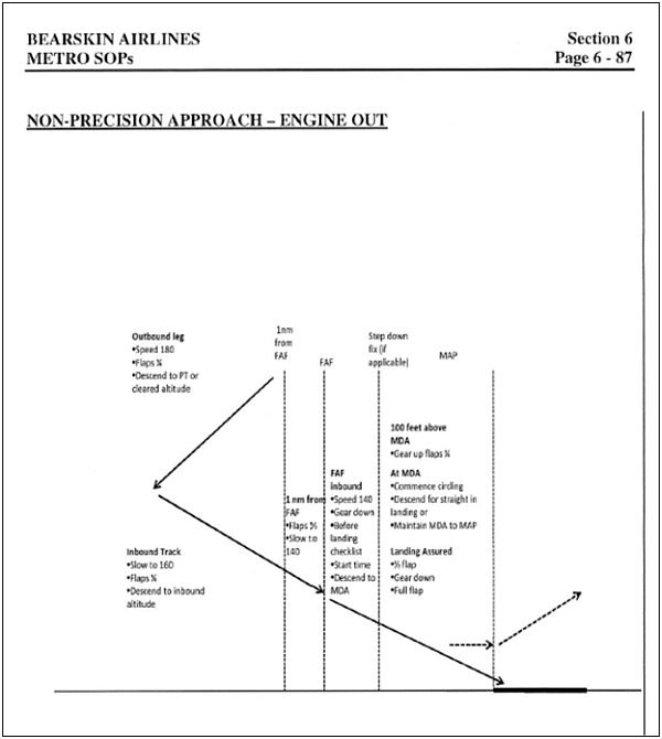
The Bearskin Airlines SOPs for a non-precision engine-out approach requires the crew to change (re-configure) the aircraft flap and gear positions 3 times during the final stages of the approach (Appendix B). Frequent configuration changes over a short distance or period of time can lead to confusion as to the configuration state of the aircraft.Footnote 16
1.18 Additional information
1.18.1 Power loss recognition
When one engine of a multi-engine aircraft experiences a loss of power, an asymmetric thrust condition occurs. Pilots may be able to detect an asymmetric thrust condition (engine power loss) by 1 of 2 methods. One is a tactile method whereby the loss of thrust on the affected engine will be noted by the pilot as decreased pressure on the failed engine's corresponding rudder pedal and an increase in pressure on the operating engine's rudder pedal. This method is commonly referred to as ‘the dead foot equals the dead engine' method. This method is less effective when the operating engine is at a low power setting (such as might be experienced on descent), as the asymmetric condition will be less apparent. Consequently, pilots commonly use visual confirmation of engine instruments to identify the engine with the power loss. Reductions in engine torque, oil pressure, and rpm's are used to identify and confirm the engine that is affected.
1.18.2 Asymmetrical thrust
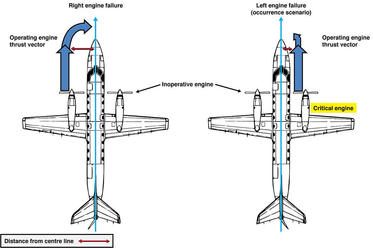
On twin-engine propeller-driven aircraft where both engines turn counter-clockwise, such as the Metro SA227, the right engine is considered critical (Figure 2). The down-going propeller blade has a larger angle of attack than the up-going blade and produces more thrust. For engines that turn counter-clockwise, the down-going blade is farther from the aircraft centre line for the left engine than for the right engine. When an engine becomes inoperative, a yaw effect will develop. The yaw effect varies with the lateral distance from the aircraft's centre line to the thrust vector of the operating engine. This is amplified by the thrust produced by the operating engine and the drag induced by the inoperative engine's propeller. Failure of the right engine will therefore result in a larger yaw effect from the operating left engine.
1.18.3 Single engine control
When thrust from engines off the centre line of an aircraft differs, control of yaw and roll relies on the tail's vertical stabilizer and rudder. The effectiveness of these surfaces increases with speed.
In this occurrence, the published VMC for the accident aircraft was 91 knots. VMC is based on the NTS system operating on the inoperative engine propeller, a 5° bank towards the operating engine, take-off power on the operating engine, landing gear retracted and the flaps in the ¼ take-off position.
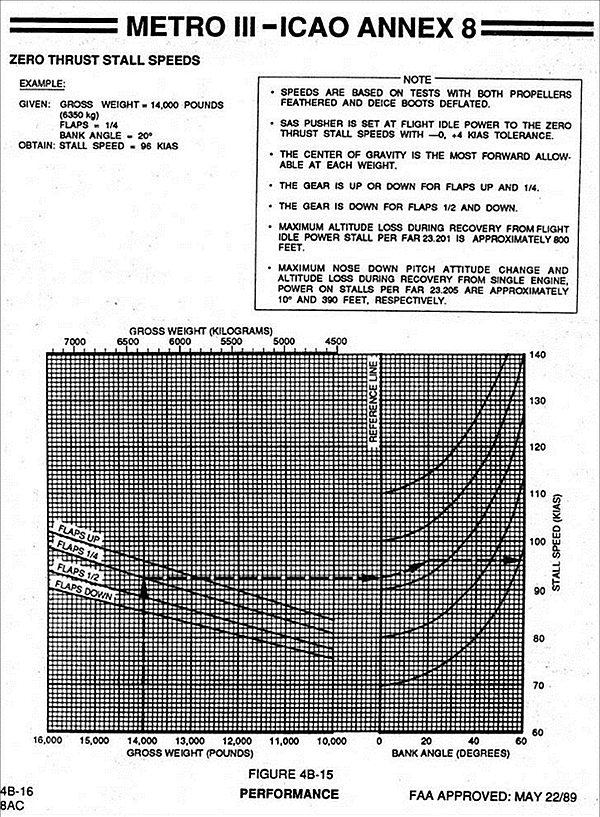
Information on the minimum speed at which directional control can be maintained with the inoperative propeller not feathered and the operative engine at a high power setting in the landing configuration VMC(L) is not normally provided to flight crews for this category of aircraft. Information as to the aircraft's stall speeds at various angles of bank is contained in the Fairchild SA227 Aircraft Operating Manual (Appendix C).
1.18.4 SA227 previous occurrences
In a previous occurrence (TSB occurrence number A09O0083) in 2009, a Fairchild SA227-DC was on final approach when the right engine (Garrett TPE331-11U-612G) suddenly failed. Information provided indicated that the failed engine's propeller NTS system was not functioning after the engine failure and that the aircraft was difficult to control until the right propeller was feathered. In accordance with the TSB Occurrence Classification Policy, the circumstances of the occurrence were assessed, and the occurrence was classified as a Class 5.Footnote 17
As part of the investigation, flight testing was conducted on a similar aircraft to assess its flight characteristics; see sub-section 1.16.1.4 Flight Test Information. Records indicate that engine failures for the TP331 engine are relatively rare. The rate of engine shutdowns for the TP331 engine is represented by a rate of 1 per 250 000 flight hours (4.00E−6).Footnote 18 Turbine blade failures occur even less frequently. There have been 22 known turbine blade failures in TP331 engines, which is represented by a forecast failure rate of 2 per 1 million flight hours (2.00E−6).Footnote 19
1.19 Useful or effective investigation techniques
1.19.1 Spectrum analysis
A spectral analysis of the CVR recording was undertaken to produce a parameter for each engine's propeller speed. The harmonic signatures were examined for interruptions in the propeller speeds that would suggest a problem or out-of-sync condition. At 1828:18, a sudden change in amplitude occured over the 6 harmonic frequency parameters that coincide with the loss of engine power. At the same time, the engine frequency harmonic showed a sudden change in amplitude and an increase in noise for the remainder of the flight. The full CVR recording was reviewed to examine the engine harmonic. The engine harmonic remained constant and steady up to the time of the occurrence, indicating that the engine event was sudden with no prior warning to the crew.
2.0 Analysis
The teardown of the left engine revealed a burnt-through stator vane. The burnt-through stator vane created a one-per-revolution vibrational excitation and allowed excessive heat stress on the first-stage turbine wheel blades. This, combined with higher porosity in one of the blade castings, inadequate fatigue capability and robustness of the blade material, and a minor increase in the mean stress in the blade fir tree region due to blade platform contact, resulted in a high-cycle blade failure. The separated portion of the failed blade damaged the remaining first-stage blades causing them to separate from the first-stage turbine wheel and pass through the remaining turbine wheels, damaging them in the process. Although the engine was severely damaged, there was enough remaining air and fuel flow so that the engine continued to run, but it produced little or no power to drive the propeller.
The discrepancies between the engine manufacturer’s maintenance manual and fuel nozzle overhaul manual created a risk that cracked or failed fuel nozzles could be re-installed after overhaul.
Currently, there is no requirement to perform a boroscope inspection of the TPE331-11U-612G’s internal engine components in conjunction with the 450-hour fuel nozzle inspection, unless fuel nozzle plugging or adverse streaking is suspected. Fuel nozzle testing for flow and streaking is not normally conducted at the same time and place as the nozzles are removed. In most cases, nozzles are removed and replaced with a spare set that have been tested previously. Plugging and/or adverse streaking would not likely be suspected until quite some time after the nozzles had been removed, which might preclude a boroscope inspection being carried out in conjunction with the fuel nozzle inspection. If there is no requirement for a boroscope inspection in conjunction with the 450-hour fuel nozzle inspection regardless of nozzle condition, there is an increased risk that premature internal engine damage will not be detected.
The engine had accumulated 2948 hours since its last major overhaul. The next major inspection was not due until 3500 hours. Failure of engine components 552 hours prior to the next inspection would be described as premature. Premature engine component failures have occurred in this engine type, but are rare.
Unexpected and premature engine failures are known to occur. To minimize the impact of engine failures and other major aircraft component malfunctions, aircraft manufacturers have developed type-specific flight crew procedures to reduce the risk of injury or damage resulting from these malfunctions.
A first-stage turbine wheel blade in the left engine failed due to a combination of metallurgical issues and stator vane burn-through which created vibration and heat stress on the turbine blade. As a result of the blade failure, the left engine continued to operate but experienced a near-total loss of power at approximately 500 feet above ground level (agl) on final approach to Runway 26 at the Red Lake Airport.
The remainder of the analysis of this occurrence will focus on type-specific flight crew procedures, and how factors specific to this occurrence affected the crew’s ability to perform them.
A spectrum analysis of the cockpit voice recorder (CVR) data indicated that the turbine blade failure was sudden and that there were no prior cockpit indications of an impending engine malfunction. The engine power loss was unexpected, and the crew had only 56 seconds between the time the left engine malfunctioned and the time the aircraft struck the trees. The crew did not verbally call out the emergency, likely due to difficulty in identifying the precise nature of the problem.
The following factors likely contributed to the crew’s difficulty in identifying the nature of the malfunction:
- The right engine was at a low power setting when the left engine power loss occurred, which would have made it difficult for the pilot flying to sense the yaw resulting from the malfunctioning engine;
- The left engine continued to run, which resulted in engine readings of 98% engine rpm, with likely normal oil pressure, exhaust gas temperature, and fuel flow. The low torque indication in the cockpit would have provided some indication of the engine problem, but it was not noticed; and
- There was little time available to identify the nature of the malfunction.
The loss of power and drop in N1 speed to 98% would have commanded the left engine propeller governor to attempt to maintain a constant engine speed of 100% by reducing the propeller blade angle. As a result, the left engine and propeller went from a low thrust condition to a high drag condition, with the fining out of the propeller blades. The left engine negative torque sensing (NTS) system was likely not operating because the engine had not completely lost power and was developing torque greater than the −4% value required to activate it. With the landing gear extended and flaps at ½, the aircraft was in a high drag asymmetric state.
The SA227’s NTS system may not always activate in response to an engine failure. The nature of the engine failure and aircraft profile may affect whether or not NTS activation parameters are reached. If pilots believe that the NTS system in the SA227 aircraft will activate in the event of any power loss or that NTS activation alone can provide adequate anti-drag protection in the event of an engine power loss, there is a risk that flight crews operating these aircraft types may not initiate the Engine Failures In Flight checklist in a timely manner.
Because the exact nature of the engine malfunction was not identified, the crew did not follow the standard operating procedures (SOPs) prescribed action of calling out the associated emergency procedure, which required them to stop and feather the propeller of the affected engine. This may have resulted from a belief that the NTS system would always activate in the event of a power loss and that NTS activation alone would provide adequate anti-drag protection from a windmilling propeller. Feathering the failed engine’s propeller would have decreased the drag associated with it and likely would have allowed the crew to maintain control of the aircraft.
Analysis of CVR information indicated that the crew had configured the aircraft for landing and, when they experienced the engine malfunction, they initially retracted the gear as though they were on an engine-out approach. They then re-selected the landing gear down before it could fully retract. It could not be determined if the company’s non-precision engine-out procedure, which requires crews to re-configure the aircraft several times over a short distance, may have influenced these actions.
At 1828:43, the crew reduced the power on the right engine to approximately 91% torque, then made a further reduction to 54% torque (presumably to initiate a descent to the runway). Flight data recorder (FDR) information indicated that the aircraft slowed to 101 knots indicated airspeed (KIAS) and banked to the left after the second power reduction. Flight test data indicated that with the aircraft in a high drag and asymmetric state, at this airspeed, the pilot flying would have had to input full aileron control deflection in an attempt to control the aircraft. Without further control input available, the pilot would have been unable to correct the aircraft’s rolling motion or recover from a stall.
At 1829:01, in response to a pilot monitoring (PM) instruction to climb, the right engine power was increased to 98% torque. This increase in power exacerbated the aircraft’s asymmetric state and resulted in the aircraft rolling left to 41° of bank. The aircraft’s stall speed in this attitude, with full flap and the landing gear down, is approximately 98 KIAS. The aircraft’s speed slowed to very nearFootnote 20 the stall speed; therefore, the loss of control was likely the result of a wing stall. There was insufficient altitude to recover.
The crew were unable to identify the nature of the engine malfunction, which prevented them from taking timely and appropriate action to control the aircraft. The nature of the engine malfunction resulted in the left propeller being at a very low blade angle, which, together with the landing configuration of the aircraft, resulted in the aircraft being in an increasingly high drag and asymmetric state. When the aircraft’s speed reduced below minimum control speed (VMC), the crew lost control at an altitude from which a recovery was not possible.
3.0 Findings
3.1 Findings as to causes and contributing factors
- A first-stage turbine wheel blade in the left engine failed due to a combination of metallurgical issues and stator vane burn-through.
- As a result of the blade failure, the left engine continued to operate but experienced a near-total loss of power at approximately 500 feet above ground level, on final approach to Runway 26 at the Red Lake Airport.
- The crew were unable to identify the nature of the engine malfunction, which prevented them from taking timely and appropriate action to control the aircraft.
- The nature of the engine malfunction resulted in the left propeller being at a very low blade angle, which, together with the landing configuration of the aircraft, resulted in the aircraft being in an increasingly high drag and asymmetric state. When the aircraft’s speed reduced below minimum control speed (VMC), the crew lost control at an altitude from which a recovery was not possible.
3.2 Findings as to risk
- If pilots believe that the negative torque sensing (NTS) system in the SA227 aircraft will activate in the event of any power loss or that NTS activation alone can provide adequate anti-drag protection in the event of an engine power loss, there is a risk that flight crews operating these aircraft types may not initiate the Engine Failures In Flight checklist in a timely manner.
- If there is no requirement for a boroscope inspection of the TPE331-11U-612G’s internal engine components in conjunction with the 450-hour fuel nozzle inspection, there is an increased risk that premature internal engine damage will not be detected.
- If there are discrepancies between the fuel nozzle testing procedures described in the TPE331-11U-612G maintenance manual and the corresponding fuel nozzle overhaul manual, there is a risk that unserviceable fuel nozzles may be evaluated as serviceable and re-installed on aircraft.
3.3 Other findings
- The SA227’s negative torque sensing (NTS) system may not always activate in response to an engine failure. The nature of the engine failure and aircraft profile may affect whether or not NTS activation parameters are reached.
4.0 Safety action
4.1 Safety action taken
4.1.1 Transportation Safety Board of Canada
The Transportation Safety Board of Canada (TSB) issued Safety Advisory 825-A13C0150-D1-A1, Operation of Aircraft with Negative Torque Sensing Systems, dated 25 April 2014. This advisory indicated that the SA227AC propeller system incorporates a negative torque sensing (NTS) system which provides cyclical anti-drag and negative torque protection for the engine if a negative torque condition is sensed. It is important to note that under certain conditions, such as an incomplete engine shutdown or certain aircraft configurations, NTS activation parameters may not be reached. Other types of aircraft also use a similar NTS system. The investigation revealed that several SA227/SA226 training manuals provide descriptions of the NTS system that might cause pilots to interpret them to mean that the system would automatically provide anti-drag protection in the event of an engine failure or power loss. The NTS system does provide partial anti-drag protection if negative torque is sensed, but not to the extent that is provided by a fully feathered propeller. Misinterpretation by flight crews of the purpose or function of the NTS system in the event of an engine power loss may lead them to believe that the NTS system will always activate in the event of a power loss or that NTS activation alone will provide adequate anti-drag protection. As a result, flight crews may not initiate the Engine Failures In Flight checklist in a timely manner. The Safety Advisory suggested that Transport Canada may wish to advise operators of these aircraft to review the NTS systems description in their training manuals and standard operating procedures (SOPs) for engine failures. The advisory further stated that particular attention should be directed to flight crews operating these aircraft types to initiate SOPs in a timely manner when an engine failure occurs.
4.1.2 Bearskin Airlines
In May 2014, the operator updated its SA227 single engine procedures.
Notable changes are as follows:
- The Engine-out, Takeoff, Engine Failure Occurs after V1 procedure will be modified to direct crews to identify the failed engine, and stop and feather the propeller upon reaching V2 prior to 400 feet.
- The Single Engine Approach procedures and diagrams have been changed to ensure the aircraft configuration remains "clean" until landing is assured.
-
The following Engine Failure on Approach checklist will be added to the SOPs and quick reference handbook (QRH) as a memory item:
Engine Failure on Approach
- POWER INCREASE TO 60% TORQUE OR HIGHER AS REQUIRED
- LANDING GEAR UP
- FLAPS 1/4
- STOP AND FEATHER (failed engine) PULL
- LANDING GEAR (landing assured) DOWN
- FLAPS AS REQUIRED
In all engine failure situations, the power lever should be advanced to MAXIMUM on the failed engine in order to minimize the drag from the windmilling propeller. Retarding the power lever on a failed engine will increase the drag on that engine and result in a control and performance penalty.
In addition, the operator indicated that the following notes will be added to the pilot flight training manual:
Most aircraft AFMs have very little guidance for handling engine failures during the approach and landing phase of flight. The assumption is that this is covered with the "Engine Failure in Flight" checklist and the "Single engine Landing" checklist. Additionally, as pilots we have proceeded with the assumption that our NTS and auto-feather systems will provide the necessary drag reduction. The problem left for pilots is to determine what action to take at what distance from the runway. If the field is "made" it would be undesirable to initiate a missed approach when a successful landing could be accomplished. It is still critical, however, to have the aircraft in a configuration for a successful landing (prop feathered and gear down). The further you are from the runway, the higher and faster you will be and the more time you will have to accomplish a feathering. The closer you are, the less time you will have and it may be necessary to initiate a missed approach in order to feather the prop. This land/no land decision will be dependent on the conditions of the day and the time that you have remaining prior to touchdown.
The operator has amended its aircraft training program to include engine failure drills (inside 1.5 miles on the approach), in the aircraft, and on all recurrent and captain upgrade training. The ground school training has been amended to include an in-depth discussion of the NTS system.
4.1.3 Transport Canada
On 15 August 2014, Transport Canada published a Civil Aviation Safety Alert (CASA 2014-04) concerning issues associated with NTS systems installed on TPE-331 series engines. This communication emphasizes the necessity for securing and verifying that propellers are feathered and secured after an engine power loss event.
4.1.4 Honeywell
- The engine manufacturer is in the process of drafting Service Bulletin TPE 331-73-0284 that would increase the frequency of inspection on TPE331-11U-612G fuel nozzles from 450 to 350 hours.
- For future production TPE331-11U-612G turbine blade castings, Honeywell will require that all turbine blades undergo a hot isostatic pressing process (HIPP) to reduce or eliminate porosity issues in turbine wheel blades.
- The TPE331-11U-612G maintenance and fuel nozzle overhaul manuals will be amended to eliminate the discrepancy between fuel nozzle testing procedures contained in the 2 manuals.
This report concludes the Transportation Safety Board’s investigation into this occurrence. The Board authorized the release of this report on . It was officially released on .
Appendices
