Loss of pitch control on landing
Canadian Pacific Railway Company
Bombardier CL-600-2B16 (Challenger 605), C-GKCP
Calgary International Airport, Alberta
The Transportation Safety Board of Canada (TSB) investigated this occurrence for the purpose of advancing transportation safety. It is not the function of the Board to assign fault or determine civil or criminal liability. This report is not created for use in the context of legal, disciplinary or other proceedings. See Ownership and use of content. Masculine pronouns and position titles may be used to signify all genders to comply with the Canadian Transportation Accident Investigation and Safety Board Act (S.C. 1989, c. 3).
Summary
On 23 February 2020, the Canadian Pacific Railway Company Bombardier CL-600-2B16 (Challenger 605) (registration C-GKCP, serial number 5945) departed Palm Beach International Airport, Florida, United States, for Calgary International Airport, Alberta, with 3 crew members and 10 passengers on board.
During the descent into the greater Calgary area, the flight crew selected flaps 20 and immediately received a “FLAPS FAIL” caution message on the engine indication and crew alerting system. The flight crew requested and received delaying vectors to the east, and proceeded to complete the flaps fail procedure in the Quick Reference Handbook. The aircraft was then sequenced back in for a zero-flap landing on Runway 17R. The aircraft touched down at 1434 Mountain Standard Time. During the landing roll, maximum reverse thrust was selected and the aircraft’s pitch attitude increased to the point where the aircraft became partially airborne for a brief moment and the rear fuselage struck the runway. During the process of recovery from the nose-high attitude, the nose landing gear struck the runway hard. The landing roll was completed and the aircraft continued to the intended parking area. There were no injuries to any of the aircraft occupants although there was significant damage to the forward fuselage.
1.0 Factual information
1.1 History of the flight
On 23 February 2020, the Canadian Pacific Railway Company (CP) Bombardier CL-600-2B16 (Challenger 605) (registration C-GKCP, serial number 5945) departed Palm Beach International Airport (KPBI), Florida, United States (U.S.), for Calgary International Airport (CYYC), Alberta, with 3 crew members (2 pilots and 1 flight attendant) and 10 passengers on board. The pilot-in-command was the pilot flying (PF) and was occupying the left seat. The second-in-command was the pilot monitoring (PM) and was occupying the right seat. The aircraft departed at 0830,Footnote 1 as planned.
During the initial approach into the CYYC area, the PF requested flaps 20, which the PM selected. The flight crew immediately received a “FLAPS FAIL” caution message on the engine indication and crew alerting system (EICAS). Data recovered from the flight data recorder (FDR) indicate the flaps deployed 1° before failing.
The PM initiated the flaps fail procedure in the Quick Reference Handbook (QRH). During the completion of the QRH procedure, the PM did not verbalize the caution notes published in the body of the procedure to the PF. The PF contacted air traffic control (ATC) to inform them of the flap condition and requested delaying vectors. ATC granted the request, and the aircraft proceeded to the east so that the flight crew could work through the flaps fail checklist (Appendix A).
The flight crew then briefed the zero-flap approach for Runway 17R. Based on a landing weight of 33 000 pounds, the flight crew briefed for VREFFootnote 2 +30 knots, or 155 knots, and a VACFootnote 3 of 160 knots.
At 1426, the PM took over radio communications and informed ATC that they were ready for the approach back to CYYC. ATC cleared the aircraft for the visual approach for Runway 17R and asked the flight crew if any assistance from aircraft rescue and fire fighting (ARFF) was required. The flight crew responded that no assistance was required. After passing 1000 feet above ground level (AGL), the PF disconnected the autopilot and remembered to disconnect the auto‑throttleFootnote 4 and advised the PM that he had done so. The rest of the final approach was uneventful.
The aircraft crossed the threshold of Runway 17R at 165 knots indicated airspeed (KIAS) and touched down at 1432:38, approximately 3000 feet from the threshold, at 154 KIAS.
Approximately 2.5 seconds after the main gear touched down, the nose landing gear contacted the runway. Two seconds later, with the control column approximately 2° forward (nose down), the PF deployed the thrust reversers and selected maximum reverse thrust. About 4.5 seconds after that, with the thrust reversers deployed, and the engines accelerating through approximately 60% N1,Footnote 5 the nose of the aircraft began to pitch up and the nose landing gear lifted off the runway, transitioning to a weight-off-wheels state.
At 1432:51, as the pitch attitude and angle of attack were increasing through 13° and 22° respectively, the PF deselected reverse thrust and applied forward input on the control column; however, the pitch attitude and angle of attack briefly continued to increase. Simultaneously, the aircraft banked approximately 3.5° to the right, and the left main landing gear briefly left the surface of the runway.
As the pitch attitude increased to a maximum of 16.9° and the angle of attack peaked at 28.9°, the aircraft’s rear fuselage struck the runway and the aft fuselage fuel dump drain mast broke off the aircraft and fell onto Runway 17R at the intersection with Taxiway U. Less than a second later, the stall protection system triggered the stick pusher function.
Approximately 1 second after the stick pusher activated, the pitch attitude was reducing at a high rate of 19° per second and the PF made a significant nose-up input on the control column, opposing the stick pusher. Despite these control inputs, the nose gear impacted the runway with a pitch rate of at least 15° per second.
Both engines were at approximately 55% N1 and decelerating at the time. The engines continued to decelerate and reached idle speed 7.5 seconds later. At this point, the aircraft’s indicated airspeed was 65 KIAS (Appendix B).
The aircraft continued to decelerate until it reached taxi speed. The crew were unaware that the rear fuselage had contacted the runway and that the fuel drain mast had broken off. The crew was instructed to taxi off Runway 17R, via Runway 26, to Taxiway A and then to their intended parking ramp. The aircraft was shut down and, after clearing customs, the passengers and crew deplaned through the main cabin entrance door. There were no injuries reported.
Following the occurrence, there were 5 aircraft movements on Runway 17R before the drain mast was reported to ATC. The crew of a flight that had just landed on Runway 17R observed a foreign object on the runway and reported it to ATC at 1450. Following the initial foreign object debris (FOD) report, ATC informed the crews of 2 subsequent flights that were about to land on Runway 17R of the debris on the runway. Both flights continued to a landing. An airport vehicle recovered the drain mast and cleared the runway by 1456. In total, 7 aircraft movements took place before the drain mast was removed from the runway, 23 minutes after the occurrence.
1.2 Injuries to persons
There were no injuries.
1.3 Damage to aircraft
The initiating event for this occurrence was the failure of the flap flexible drive shaft connecting the 2 left inboard flap actuators. When the flap control unit sensed a potential asymmetric flap condition developing, the “FLAPS FAIL” caution message was displayed on the EICAS, and the flap system stopped operating, limiting the possibility of difficulty in controlling the aircraft due to an asymmetric flap condition.
During the landing roll, the rear fuselage and tail cone made contact with the runway surface. As a result, the aft fuselage fuel drain mast broke off the aircraft and the lower skin of the tail fairing received significant abrasion damage (Figure 1).
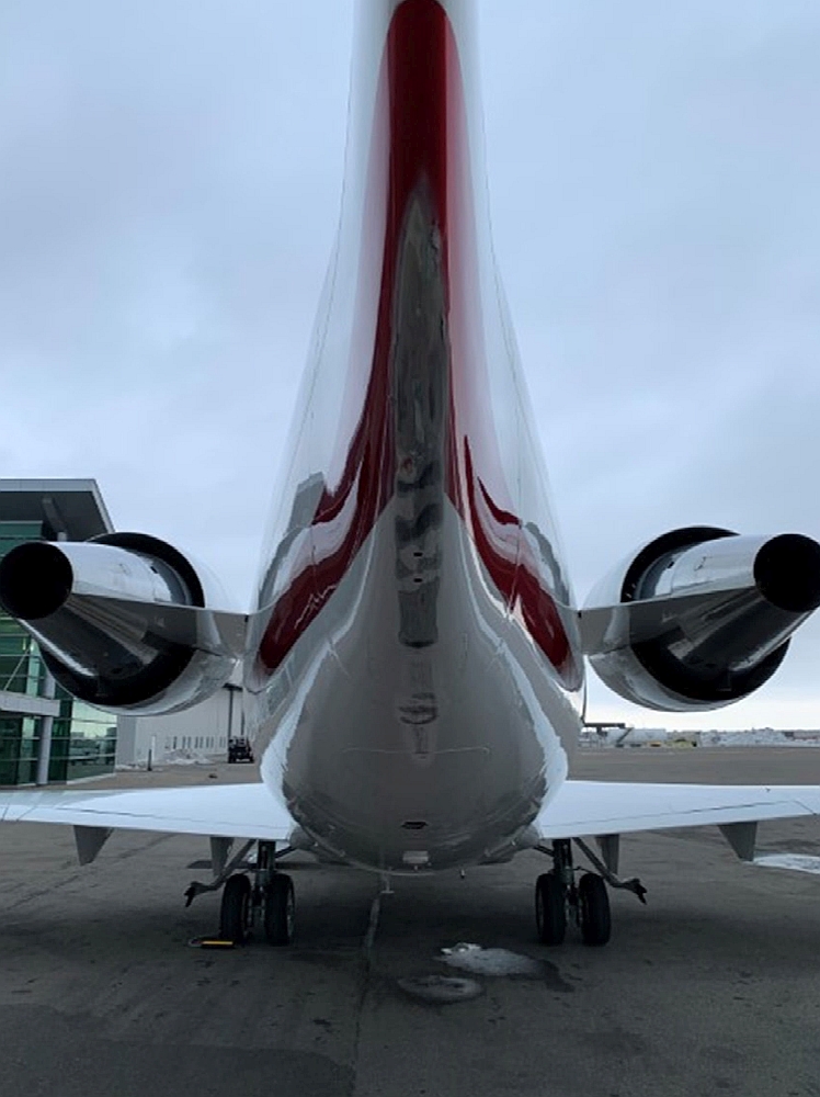
The drain mast measures approximately 13 inches long, 8 inches high, 3 inches wide, and weighs 1.1 pounds. It is constructed primarily of carbon fiber composite with aluminum tubing installed internally. The tubing is connected to the aircraft’s fuel system.
The lower forward fuselage sustained significant structural damage when the nose landing gear made contact with the runway after the aircraft pitched up. The left and right lower fuselage skins adjacent to the nose landing gear were deformed. Several fuselage frames were damaged in the lower forward fuselage, and there was deformation of both the left and right nose landing gear upper torque box structure due to the overload experienced during impact with the runway.
1.4 Other damage
No damage to other aircraft or property was reported.
1.5 Personnel information
1.5.1 General
Records indicate that both flight crew members were certified and qualified for the flight in accordance with existing regulations. Based on a review of the flight crew’s work and rest schedules, fatigue was not considered a factor in the occurrence. Both flight crew members were rated as captains on the aircraft type and had previously flown the occurrence aircraft together on numerous occasions.
| Pilot-in-command | Second-in-command | |
|---|---|---|
Pilot licence |
Airline transport pilot licence (ATPL) |
ATPL |
Medical expiry date |
01 April 2020 |
01 June 2020 |
Total flying hours |
9478 |
20 450 |
Flight hours on type |
434 |
953 |
Flight hours in the 7 days before the occurrence |
10.9 |
10.9 |
Flight hours in the 30 days before the occurrence |
16.3 |
24.4 |
Flight hours in the 90 days before the occurrence |
39.9 |
40 |
Flight hours on type in the 90 days before the occurrence |
39.9 |
40 |
Hours on duty before the occurrence |
8 |
8 |
Hours off duty before the work period |
63 |
63 |
1.5.2 Pilot-in-command
The pilot-in-command began working at CP on 15 December 2017. In addition to the CL64 type rating for the Challenger 605, he held type ratings on the Beech 1900D, the Cessna Citation Sovereign, the Hawker 125, the Dassault Falcon 2000, and the Swearingen Metroliner.
The pilot-in-command successfully completed initial training for the CL64 type rating on 17 February 2018 and completed recurrent training for the CL64 type rating with a flight training provider in the U.S. on 06 February 2020. During that training regime, flap failure procedures—including zero-flap landing exercises—were practiced in a Level D full flight simulator. The pilot-in-command’s flight training record showed that he was assessed as being proficient on the flap configuration exercise.
The pilot-in-command had last completed crew resource management training on 01 October 2019.
1.5.3 Second-in-command
The second-in-command began working at CP on 07 April 2006. In addition to the CL64 type rating for the Challenger 605, he held type ratings on the Cessna Citation 550, 560 and 680; the Dassault Falcon 50; and the Hawker 125.
The second-in-command successfully completed initial training for the CL64 type rating on 24 February 2017 and completed recurrent training for the CL64 type rating with the pilot-in-command on 06 February 2020. The second-in-command’s flight training record showed that he had also been assessed as proficient on the flap configuration exercise.
The second-in-command had last completed crew resource management training on 12 May 2019.
1.5.4 Flight attendant
The flight attendant began working at CP in 2012 in another capacity. On 03 November 2017, he completed an initial cabin crew training program online, and began flying as a cabin crew member in 2018. The flight attendant met all regulatory training requirements to perform the duties of a flight attendant.
1.6 Aircraft information
1.6.1 General
The Bombardier Challenger 605 is a swept-wing aircraft with a T-tail. It is constructed primarily of aluminum and powered by twin turbofan engines mounted high on the aft fuselage. The Challenger 605 is an evolution of the Challenger 600, originally certified in August 1980, and is considered a transport category aircraft. As at 31 January 2020, there were 1014 Challenger seriesFootnote 6 aircraft in service worldwide.
| Manufacturer | Bombardier Inc. (formerly Canadair) |
|---|---|
| Type, model and registration | Challenger CL-600-2B16 (604 Variant), C-GKCP |
| Year of manufacture | 2013 |
| Serial number | 5945 |
| Certificate of airworthiness/flight permit issue date | 14 April 2017 |
| Total airframe time / cycles | 1699.3 / 920 |
| Engine type (number of engines) | General Electric CF34-3B (2) |
| Maximum allowable takeoff weight | 21 863 kg |
| Recommended fuel type(s) | Jet A, Jet A-1, Jet B |
| Fuel type used | Jet A |
The aircraft was configured for a maximum of 3 flight crew members (2 pilot seats and a jump seat) and up to 12 passengers. The occurrence aircraft received its initial certificate of airworthiness upon manufacture in June 2013, entered service in February 2015, and was purchased by CP in 2017.
When the aircraft entered service in February 2015, it had accumulated a total of 27.3 flight hours and 13 landings. From February 2015 to the occurrence date, the aircraft flew an average of 340 flight hours annually. Therefore, from the time the aircraft received its initial certificate of airworthiness in June 2013 to the occurrence date, the aircraft flew an average of 283 flight hours annually, and performed an average of 153 landings per year.
Records indicate that the aircraft was certified, equipped, and maintained in accordance with existing regulations and approved procedures. The investigation determined that the aircraft was being operated within weight and balance limits during the occurrence flight.
1.6.2 Flap system
1.6.2.1 General
The Challenger 605 flap system consists of inboard flap panels (left and right), outboard flap panels (left and right), a flap power drive unit, flap flexible drive shafts (10), flap actuators (8), flap brake detector units (2), a flap control unit, and, in the cockpit, a flap selection lever.
Under normal conditions of operation, the flap power drive unit—located in the main landing gear bay—powers the flap actuators via the flap flexible drive shafts, and the flaps are held in the selected position by the flap brake detector units. The flap control unit monitors system operation and if the unit detects a fault with a component in the flap system, the appropriate message is displayed to the flight crew on the EICAS, and the system is disabled. There is no alternate means of flap operation. A review was conducted of the various Challenger series of aircraft to compare the flap flexible drive shaft part numbers. It was determined that none of the flap flexible drive shaft part numbers for the Challenger 605 had changed from the original Challenger 600.
In this occurrence, the left-hand flap flexible drive shaftFootnote 7 that connects the inboard and outboard actuators of the left-hand inboard flap, sheared where the flexible inner core is swaged to the outboard flap actuator drive end (Figure 2).

1.6.2.2 Manufacturer’s maintenance recommendations
The aircraft manufacturer publishes a schedule for required maintenance, including specific maintenance tasks and the intervals at which the tasks need to be completed.Footnote 8 The task intervals are specified in flight hours, flight cycles, calendar time, or a combination of one or more of those, and are based on an average aircraft utilization of 500 flight hours and 300 flight cycles in 12 calendar months.
As part of the Bombardier customer service program, the company actively tracks fleet utilization across its product line. For the 12 calendar months ending 31 January 2020, the Challenger 605 fleet had an average annual utilization of 275 flight hours and 144 landings.Footnote 9
1.6.2.2.1 Flap flexible drive shaft inspection
Task 275000-202 requires a detailed inspection of the flap flexible drive shafts at an interval of 2400 flight hours.Footnote 10 The inspection task is to be completed in accordance with task 27-53-07-220-801 of the Aircraft Maintenance ManualFootnote 11 and includes the removal and visual inspection of the inner core of the flap flexible drive shaft. If the inner core has dry or hard grease evident, it is to be cleaned, inspected, and serviced before being reinstalled in the aircraft.
At the time of the occurrence, the flap flexible drive shafts had accumulated 1699.3 hours since new. Therefore, because the aircraft had not accumulated 2400 hours of flight time, the inspection had not been carried out, nor was it required to have been. This flap flexible drive shaft would have last been inspected to some degree before the original installation on the aircraft at manufacture in 2013. As such, the component had never been inspected by maintenance personnel.
The failed flap flexible drive shaft was sent to the TSB Engineering Laboratory in Ottawa, Ontario, for analysis to determine why the part had failed.
The TSB Engineering Laboratory conducted a detailed examination of the part, which revealed 2 puncture holes in the protective outer casing under the data plate for the part. These holes were likely introduced as an unintended consequence during the manufacturing process of the drive shaft assembly, when the data plate was being installed. These holes would have allowed water moisture to enter the flap flexible drive shaft housing cavity, allowing corrosion to begin. In addition, both the inboard and outboard segments of the inner drive shaft showed significant corrosion and lack of lubrication.
Whenever there is a mechanical connection in a component or system, there is the potential for a sealed environment to be compromised. In this case, the sealed environment is the inner part of the flap drive shaft housing where the flexible drive shaft core resides and rotates. The flap flexible drive shaft assembly is connected via a threaded coupling nut to both the inboard and outboard flap actuator assemblies of the left inboard flap panel. As such, this then becomes an area of potential leakage into the sealed environment. If there is an imperfect seal between the face of the flap actuator and the face of the flap flexible drive shaft casing, water moisture and other contaminants can penetrate the core of the drive shaft housing and corrosion of the drive shaft core can result.
1.6.2.3 Service difficulty reports
A review of Transport Canada’s (TC’s) Web Service Difficulty Reporting System from 1986 to 2020 revealed 4 instancesFootnote 12 (including the report for the occurrence aircraft) of service issues with the flap flexible drive shafts installed in the Challenger 600 series of aircraft that required the part to be replaced (Appendix C).
From May 2016 to May 2020, Bombardier sold 484 flap flexible drive shafts to Challenger 600 series customers and operators (Table 3). It could not be determined which series of aircraft the various parts were being installed on, what defect had been found that required the part to be replaced, or what the part’s time in service was when it needed to be replaced.
| Bombardier part number (vendor part number) | Units sold |
|---|---|
600-93000-61 (2022264-6) |
154 |
600-93000-63 (2022264-7) |
67 |
600-93000-65 (2022264-8) |
110 |
600-93000-67 (2022264-9) |
57 |
600-93000-69 (2022264-10) |
96 |
Total |
484 |
1.6.3 Landing procedures
Landing procedures are described in the following Bombardier documents:
- Aircraft Flight Manual (AFM)
- Flight Crew Operating Manual (FCOM)
- Quick Reference Handbook (QRH)
The AFM and FCOM describe the aircraft limitations, operating procedures, and the performance capabilities of the aircraft, and guide the flight crew on the recommended operating procedures for the Challenger 605 aircraft in normal, abnormal, and emergency operations. The QRH contains checklists for abnormal and emergency procedures. The checklists are designed to provide the flight crew with important and timely information in an abbreviated format so crucial steps can be accomplished quickly and correctly, and to reduce the risk of operating an aircraft in an abnormal state.
The normal procedure for a full stop landing is outlined in the FCOM.Footnote 13 Table 4 is a simplified version of the procedure.
| Speed | Step | Control | Actions required | Typical handling |
|---|---|---|---|---|
Above 60 KIAS |
1 |
Thrust levers |
Select to idle at or below 50 feet |
- Prepare approach and land as required - Main gear touchdown - Control column released to lower nose gear to runway - Nose gear touchdown |
2 |
Flight spoilers |
Select |
To maximum |
|
3 |
Brakes |
Apply |
Appropriate for runway conditions |
|
4 |
Thrust reverse |
Lift (and pull back) |
- Forward pressure to keep nose down (nose down elevator applied) - Select (adjust) |
|
5 |
Thrust reverse |
Pull back (and set) |
- Forward pressure to keep nose down (nose down elevator applied) - Select (adjust) |
|
6 |
Rudder ailerons |
Use |
As required |
|
7 |
Instruments/speed |
Monitor |
Observe limitations |
|
60 KIAS and below |
8 |
Thrust reverse |
Select |
Reduce or stow |
9 |
Nose wheel steering |
Use |
As required |
The full stop landing procedure includes the following caution to emphasize the aircraft’s particular handling characteristic:
CAUTION
With thrust reversers deployed, a nose-up pitching tendency will occur at high power settings, particularly at aft center of gravity light weights. This tendency is controllable with elevator and may be minimized by ensuring that nose wheel touchdown is achieved and nose down elevator applied, before selecting reverse thrust.Footnote 14
This same caution is included in the abnormal procedures for a flap failure described in the AFMFootnote 15 and the FCOM.Footnote 16 These documents also include the following caution:
CAUTION
Improper landing technique during a flaps failure can generate nose gear loads sufficient to cause structural damage.
To prevent damage:
- After main gear touchdown, gently lower the nose to the runway.
- Apply brakes only after nose wheel touchdown.Footnote 17,Footnote 18
The QRH includes the following caution between steps 12 and 13:
CAUTION: ATS [auto throttle system] will not transition to landing mode and will not retard thrust levers at 50 feet AGL.Footnote 19
In addition, the QRH includes these cautions after step 14:
CAUTION:
Improper landing technique during a flaps failure can generate nose gear loads sufficient to cause structural damage.
To prevent damage:
- After main gear touchdown, gently lower the nose to the runway.
- Apply brakes only after nose wheel touchdown.
- Before selecting reverse thrust, ensure that the nose wheel has touched down, and nose down elevator is applied.Footnote 20
None of these documents specify the amount of pressure or how much elevator control input is required before selecting reverse thrust during landing.
During completion of the QRH checklist, the PM did not communicate these cautions to the PF.
1.6.4 Operational evaluation of the Bombardier Challenger 605
In 2006, an operational evaluation of the Bombardier Challenger 605 was conducted by representatives from TC, the U.S. Federal Aviation Administration (FAA), and the European Aviation Safety Agency (EASA) / Joint Aviation Authorities.
Following the evaluation, both the FAA and the EASA / Joint Aviation Authorities published reports that define the training and cross training requirements to allow pilots to hold the appropriate aircraft type rating for the Challenger 604 / Challenger 605. The reports also provide information on training program items that should be given special emphasis. With respect to zero-flap approaches and landings, the reports state the following:
[…] zero-flap approaches and landings to a full stop are required to be demonstrated by applicants seeking type certification in this aircraft. The aircraft’s trailing edge flap extension is powered by the electrical system and there is no alternate means of flap operation in the case of electrical system failure. The aircraft has a relatively high approach and landing speed and has a tendency to “float” if normal landing flare technique is used. Thrust reverser deployment during a zero flap landing tends to cause the nose to pitch-up, requiring significant pilot input to maintain nose wheel contact with the runwayFootnote 21,Footnote 22
TC did not publish an operational evaluation board report for the Challenger 604/605 following the evaluation.
1.7 Meteorological information
The aerodrome routine meteorological report (METAR) for CYYC issued at 1400 and valid at the time of the occurrence indicated the following:
- winds from 120° true, at 9 knots
- visibility 40 statute miles
- clouds broken at 2500 feet, 9000 feet, and 25 000 feet AGL
- temperature 0 °C
- altimeter setting 29.68 inches of mercury
Weather was not considered a factor in this occurrence.
1.8 Aids to navigation
Not applicable.
1.9 Communications
Not applicable.
1.10 Aerodrome information
1.10.1 General
CYYC is one of Canada’s busiest airports by passenger traffic numbers. In 2019, the facility handled 18 million passengers. Although the airport facility currently has 4 runways available for use, the majority of flights arriving and departing CYYC use either of the 2 main north/south runways (17L/35R and 17R/35L). Runway 17R/35L is paved and 12 675 feet long and 200 feet wide. The airport facility does not have an automated FOD detection system installed, nor is it required to have one. The airport does, however, have protocols in place for monitoring the airport property and aircraft movement areas to detect and remove FOD from the facility.
1.10.1.2 Runway foreign object debris detection
The Calgary Airport Authority has developed an inspection program, which is included in its TC-accepted Airport Operations Manual, to proactively maintain a safe operating environment at the airport. In accordance with the program, the runways are inspected at least 4 times per day. An airfield operations specialist will drive down the runway to conduct a visual inspection of the runway surface condition and to detect any foreign objects that may be present, with special attention being paid to the center 100 feet of the runway. The results of the inspection are then entered in the airport’s computer tracking system.Footnote 23
On 23 February 2020, the last visual inspection of Runway 17R/35L before the accident was carried out at 0840, just less than 6 hours before the accident.
1.11 Flight recorders
The occurrence aircraft was equipped with both a cockpit voice recorder (CVR) and an FDR. Both recorders were located in the aft equipment bay (rear fuselage) of the aircraft. They were removed and sent to the TSB Engineering Laboratory in Ottawa, Ontario, for data download and analysis.
The audio recorded by the CVR was considered of good quality.
In addition to the occurrence landing, data from the previous 12 landings were also downloaded from the FDR for observation and analysis.
1.12 Wreckage and impact information
Not applicable.
1.13 Medical and pathological information
The investigation determined that there was nothing to indicate that the pilot-in-command’s or second-in-command’s performance was degraded by medical, pathological, or physiological factors.
1.14 Fire
There was no fire.
1.15 Survival aspects
Not applicable.
1.16 Tests and research
1.16.1 TSB laboratory reports
The TSB completed the following laboratory report in support of this investigation:
- LP057/2020 – Flap Flexible Drive Shaft Failure Analysis
1.17 Organizational and management information
CP’s flight department operates under Subpart 604 of the Canadian Aviation Regulations (CARs)Footnote 24 and holds a private operator registration document (PORD), which was issued by TC on 26 June 2018. The flight department operates and maintains 2 aircraft: the occurrence aircraft and a Cessna Citation 680 Sovereign. The department operates out of a commercial fixed base operator facility located at CYYC.
1.17.1 Company operations manual
In accordance with the regulations,Footnote 25 CP has a Company Operations Manual that defines how the flight department operates, who the key personnel in the department are, and their roles and responsibilities within the department.
1.17.2 Challenger 605 standard operating procedures
The CP flight department has standard operating procedures (SOPs) specifically for the operation of the Challenger 605. At the time of the occurrence, the document was relatively new to the organization, as it was first issued on 30 December 2019. The purpose of the document is to:
- Identify and describe the standard tasks and duties of the flight crew for each phase of flight; and
- Assist CP Rail pilots to operate the CL605 [Challenger 605] within the limitations of the AFM.Footnote 26
The document also notes,
SOPs (including standard calls) constitute the reference for crew standardization and provide the working environment required for enhanced and efficient crew communication and coordination.Footnote 27
The SOPs address crew coordination during abnormal and emergency situations and include a section specifically on passenger briefings, which emphasizes the passengers’ need and right to know what is happening in an emergency situation. The document further states that the passengers should be provided with an honest and accurate summary of the situation with the intent to instill confidence in the flight crew, and the briefing is to include instructions deemed appropriate to the circumstances of the abnormal or emergency situation.Footnote 28
At no point during the occurrence did the flight crew brief the passengers or the flight attendant on the abnormal condition of the aircraft or the different landing configuration.
1.17.2 Flight attendant procedures
Although not required by the regulations,Footnote 29 CP occasionally used a flight attendant on board the Challenger. The company provided training to its flight attendant in accordance with the provisions set out in a TC exemption,Footnote 30 which allowed it to train its flight attendant to a level equivalent to the persons assigned on-board duties level set out in subsection 724.115(30) of the Commercial Air Services Standards.
Neither the Company Operations Manual nor the Challenger 605 SOPs detail any specific duties or responsibilities for the flight attendant, or recommend strategies for how a flight attendant should be used by the flight crew under normal or abnormal situations.
1.18 Additional information
1.18.1 Canadair Regional Jet 100/200 series aircraft
In the late 1980s, Canadair began developing a 50-seat regional jet based on the Challenger 600 series airframe and systems. The aircraft, designated as the Canadair Regional Jet (CRJ), first took flight in May 1991.
Because the CRJ was based on the Challenger series of aircraft, the 2 aircraft types have many similar aircraft systems designs, including the flap system. The flap power drive unit, flap flexible drive shafts, and flap actuators were originally of similar design. However, in-service experience of CRJ operators necessitated design changes to the flap drive system to improve reliability and reduce the resultant unscheduled down time of the aircraft as the system matured.
As such, some comparisons can be made between the 2 aircraft and their respective flap systems and their maintenance requirements.
1.18.1.1 Maintenance requirements
The flap flexible drive shafts on the CRJ are subject to the following maintenance actions:
- Detailed external inspection of the flap flexible drive shafts at a 1500 flight-hour interval.Footnote 31
- Lubrication of the flap system, including the flexible drive shaft, which also requires a detailed inspection of the flap flexible drive shaft inner core at a 4000 flight-hour interval.Footnote 32
- Detailed inspection of the flap flexible drive shaft core at a 5000 flight-hour interval.Footnote 33 This includes a visual inspection of the flap actuator sealing face and the task card highlights areas where water ingress may occur due to sealing face damage (Appendix E).
1.18.1.1.1 Service bulletin
In July 2007, after determining that internal contamination was a significant in-service issue on CRJ 100/200 series aircraft, Bombardier issued a service bulletinFootnote 34,Footnote 35 with instructions for inspecting the flap flexible drive shafts and flap actuators for contamination. The service bulletin included procedures to:
- Do a detailed inspection, remove moisture, clean, and lubricate the flexible drive-shafts. If applicable, to install a new metallic sealing washer.
- Do a pressure test of the flexible drive-shafts to find leaks.Footnote 36
This service bulletin introduced a number of maintenance measures and product improvements to increase the reliability of the flap flexible drive shafts and flap actuators. These measures included:
- installing a new seal between the flap drive shaft casing (specific part number) and the flap actuator housing during installation;
- applying sealant to both sides of the installed seal if minor damage was noted on the sealing faces of the drive shaft casing or flap actuator;
- increasing the torque on the flap drive shaft securing nut from 70–80 inch-pounds to 160–180 inch-pounds;
- completing a pressure test of the drive shaft housing to ensure there are no leaks present that could allow moisture to enter the drive shaft assembly; and
- performing a low-temperature torque test of the flap actuators.
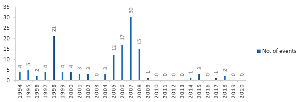
A search of service difficulty reports related to flap malfunctions directly attributable to flap flexible drive shaft failure yielded the data presented in Figure 3. Although the number of service difficulty reports decreased significantly starting in 2009, it could not be determined if this was as a result of the service bulletin actions, or as a result of reduced worldwide fleet utilization.
1.18.2 Crew resource management
The objective of crew resource management (CRM) is to reduce human error in aviation. CRM is widely accepted as the use of all human, hardware, and information resources available to the flight crew to ensure safe and efficient flight operations. Effective CRM encourages the flight crew to use all resources at their disposal to effectively handle both normal and emergency procedures. To that end, a flight attendant would be considered a resource available to the flight crew to allow them to operate effectively as a team, and cope better with non-routine (abnormal) situations.
CP provided CRM training to both flight crew members annually and provided CRM training to the flight attendant every 3 years. The content of the CRM training material is not specified in the regulations, and the training was provided by a third party.
1.18.3 Checklist usage
Checklists are critical information resources that provide procedural guidance to pilots for the operation of an aircraft. They assist with pilot decision making, providing pilots with predetermined solutions to various situations. They also account for risk factors that may not be readily apparent to a pilot during normal operations or during an abnormal or emergency situation. Checklist discipline involves following the appropriate checklist or procedure, which in turn provides pilots with the safest and most efficient course of action in most cases.
The Challenger 605 QRH expands on items that require emphasis with a note, caution, or warning. The QRH explains the difference between the 3, in increasing order of importance, as follows:
NOTE: Information that provides special emphasis on aspects of a procedure, and may be safety related.
Image
CAUTION: Information that is considered important and may negatively impact the safe outcome of the procedure or lead to adverse effects or damage if not considered by the crew.
Image
WARNING: Information that is considered critical for the safe outcome of the procedure and may result in injury or loss of life if not followed.Footnote 37
Issues involving checklist usage (specifically checklist discipline) have been identified in several previous TSB investigation reports.Footnote 38
1.18.4 Human performance
1.18.4.1 Acquiring knowledge, rules and skills
Knowledge-based performance is largely conscious, occurring as an individual learns new situations and outcomes. As training progresses, rules will be learned to produce more regulated if-then performance.Footnote 39 With experience, performance will become more automatic, where the individual responds appropriately upon perceiving relevant cues, for example, when A happens, the individual will perform B. In turn, if A doesn’t happen, B will not occur. This is how a person develops a mental model about the situations and circumstances in which they are operating.
Having an accurate mental model helps an individual filter, organize, and act on large amounts of information quickly and error-free.Footnote 40 Practicing tasks that are performed less frequently or are less familiar, such as abnormal procedures, enables a person to develop, to some degree, the skills required to perform the actions. When a scenario requires the performance of these less familiar tasks, individuals rely on memory prompts to help initiate the appropriate sequence of actions. Training helps the individual develop the mental model, which allows them to anticipate the workload and potential consequences of the tasks ahead.Footnote 41
Organizational training and documented operational and emergency procedures are key to communicating and reinforcing required knowledge and rules. However, if such documentation and/or training do not accurately describe the required knowledge or rules, then actual performance may differ from what is required. Further, if there is no system in place to capture such performance deviations, then repeated practice will serve to reinforce and strengthen such (incorrect) behavioural habits.
When physically performing a task, such as handling the control column and the aircraft during a flap failure, a pilot learns the associated skilled actions for that task. With practice, these motor actions create motor memories and the pilot develops the required skills.Footnote 42 During this process, each step in the sequence automatically prompts the next step in the sequence with minimal use of attentional resources. This skill acquisition process is particularly important when the pilot is required to perform in an abnormal procedure or emergency, whilst under high workload conditions. In such circumstances, the trained pilot, with limited time and cognitive capacity, is more likely to be able to perform the task rapidly, accurately and without much thought.
Conversely, if a pilot does not practice a physical task regularly to the point that motor memories develop and the pilot can perform it with minimal attentional resources, then performance of such a task may be negatively affected or may not occur at all while under stress. Further, if a less-frequently performed task is too similar to another well-practiced task for which the pilot does have strong motor memories, then the actions for the more mastered task may be triggered instead.
1.18.4.2 Prompting knowledge, rules, and skills
When acquiring knowledge, rules, and skills for specific tasks, some of that information is processed and stored in long-term memory and individuals do not have to re-read the procedure to remind themselves of the steps to be taken each time the task is performed.Footnote 43 This is particularly true for tasks that are practiced routinely, such as aircraft handling during normal landing procedures.
For tasks that are performed less frequently, operational documentation, such as the QRH, serve to prompt recall of particular tasks and steps and the order in which such steps should be taken. This allows pilots to operate in and respond to a range of scenarios, as they are not limited to only those tasks they fully remember.
However, when less familiar scenarios do occur, if such prompts are not provided or accessed, performance may not occur or may be incorrect.Footnote 44 This is especially true for tasks that have not developed motor memories as a result of repeated practice.
1.18.4.3 Cognitive bias and decision making
Organizing and simplifying information lessens the burden on information processing capacity. Although such information management can facilitate effective performance in some conditions, sometimes it can result in strong performance biases that lead to unsafe decisions and assumptions.
One such decision making bias is the availability heuristic, which focuses on the timing of an individual’s experience, “in that more recent events or conditions in the world generally are recalled more easily,”Footnote 45 i.e. the person may make an assumption or diagnosis based on more recent experiences, for example, recent simulator-based abnormal procedures.
Typically, the more uncertain the individual is about their decision or diagnosis of a situation, the more information is likely to be sought. However, “[i]f one is more confident than is warranted in the correctness of one’s hypothesis, then one will not be likely to seek additional information.”Footnote 46 This is known as overconfidence bias, and “[t]he false hypothesis can be extremely resistant to correction,”Footnote 47 especially when expectancy is high and when attention is diverted elsewhere in the flight.
1.18.5 Flight simulator certification
Full flight simulators are currently rated according to 4 levels: Level A through Level D, with Level D being the most sophisticated. It is intended to replicate actual aircraft operating and handling characteristics, such that all aircraft type training can be accomplished in the device, without requiring additional training in a physical aircraft, even if the pilot has no prior experience in the aircraft type.
Level D simulators replicate aircraft system behaviours with high fidelity and in such a way that allows the use of the type-specific normal, abnormal, and emergency procedures for training and checking. This provides flight crews with the opportunity to make an error, learn from that error, and practice the exercise until it can be satisfactorily completed.
TC,Footnote 48 the FAA,Footnote 49 and EASAFootnote 50 have all published documents containing certification requirements for the various levels of full flight simulators. None of these documents contain a certification requirement for Level D simulators to replicate possible pitch changes during aircraft operation after the nose wheel has touched down on the runway. The requirements for flight simulator certification during the landing phase is placed on directional control, deceleration characteristics, airframe buffet effect, and accurate aircraft systems simulation.
Data collected during the investigation indicated that the Level D simulator used by the flight crew in their most recent training did not produce a pitch up moment upon thrust reverse selection nor was it required to by certification standards.
1.18.6 Effects of thrust reversers on jet aircraft
The FAA’s Airplane Flying Handbook provides pilots with relevant information on flying airplanes in general. It also provides more in-depth information for pilots who are transitioning to more advanced aircraft types. For example, it includes the following information in its specific description of the operation and effects of thrust reversers on jet aircraft:
Reverse thrust is much more effective at high airplane speed than at low airplane speeds for two reasons: the net amount of reverse thrust increases with speed; and the power produced is higher at higher speeds because of the increased rate of doing work. […]
When considering the proper time to apply reverse thrust after touchdown, the pilot should remember that some airplanes tend to pitch nose up when reverse is selected on landing and this effect, particularly when combined with the nose-up pitch effect from the spoilers, can cause the airplane to leave the ground again momentarily. On these types, the airplane must be firmly on the ground with the nose wheel down before reverse is selected.Footnote 51
1.18.7 Foreign object debris
FOD, in this circumstance, would be any object on airport property that is in an inappropriate location and, as a result of its location, could cause damage to persons, equipment, or the environment. Examples of FOD include parts from operating aircraft or airport maintenance equipment, garbage, or tools used by aircraft or airport maintenance personnel.
In 1998, Boeing published an articleFootnote 52 that estimated that, at that time, the damage resulting from FOD incidents cost the worldwide aviation industry approximately $4 billion dollars a year in damage to equipment and aircraft, and injuries to persons.
One of the most well-known cases of undetected FOD on a runway causing damage to an aircraft is that of Air France flight 4590, which departed Charles de Gaulle Airport in Paris, France, on 25 July 2000.Footnote 53 In that occurrence, the Concorde aircraft ran over a strip of stainless steel debris that had fallen to the runway from the preceding departure of a Continental Airlines DC-10 and went undetected. As a result, a left main landing gear tire exploded on the Concorde and the resultant tire debris ruptured one of the aircraft’s fuel tanks, which led to a fuel leak and fire. The aircraft continued with the takeoff, but subsequently crashed. All those on board and 4 people on the ground were fatally injured.
1.18.7.1 Vancouver International Airport
The Vancouver International Airport (CYVR), British Columbia, is one of Canada’s busiest airports. In 2018, 25.9 million passengers used the facility, and the runways handled 338 073 takeoffs and landings. The facility consists of 2 main east/west runways (08R/26L and 08L/26R) and Runway 13/31. The majority of aircraft movements use the east/west runways.
In 2007, following an internal risk assessment that identified a deficiency in the airport’s ability to adequately monitor the surface condition of the 2 main runways, the airport authority installed an automatic ground-based radar system for detecting FOD on the runway.
A sensor is located approximately 25% of the way down from either end of both runways. The radar sensors scan an arc, which includes the threshold of the runway to a point approximately 75% down the length of the runway, and are networked together to a common display in the airport operations center. In addition, high-definition cameras are installed on the towers that support the infrastructure for the radar equipment. These cameras have infrared capabilities allowing them to be used at night.
When FOD is detected on a runway surface, an audible and visual alert is produced and the location of the FOD is displayed on the map portion of the system display. Concurrently, the system points the appropriate camera at the unidentified object so that airport personnel can visually confirm the object that has been detected on the runway. Once the FOD has been visually confirmed, the event is run through a risk matrix to determine whether or not it is necessary to close down the runway and send personnel out to inspect the runway and deal with the object.
It is important to note that this automated FOD detection system does not replace the regularly scheduled visual runway FOD surveillance activities performed by airport personnel. The system augments these visual inspections and is an additional resource available to the airport authority to ensure the runways remain clear of FOD.
At the time of drafting this report, CYVR was the only commercial airport in Canada to have installed an automated FOD detection system for runways.
1.18.8 Similar occurrences
Data from various air safety agencies was reviewed to determine if any occurrences with similar circumstances to this occurrence had occurred. Two similar instances were found, with the most recent one taking place subsequent to this occurrence in 2020, and one that occurred in 1999.
On 28 November 2020, a foreign registered Challenger 605 departed Antalya International Airport, Turkey (LTAI) on a commercial charter flight to Moscow/Vnukovo International Airport, Russia (UUWW). After completing a flaps 20 departure, the flight crew selected flaps up, and subsequently received a flap fail caution message with the flaps stopped at 14°. The flight crew elected to return to LTAI. During the landing roll, the crew selected reverse thrust and the nose of the aircraft pitched up to maximum of 16.7° and the rear fuselage struck the runway. The aircraft sustained damage to the aft fuel jettison drain mast, tail cone assembly and tail fuel tank fairing. Preliminary FDR data indicates that at the time of thrust reverser deployment, the control column was between 0° and 1° nose up.
A second occurrence had been investigated by the FAA in 1999.
That occurrence, which took place at the Long Beach Airport, California, U.S., on 06 May 1999, involved a Challenger 604. The narrative reads as follows:
During a high speed taxi for a maintenance test, the aircraft became airborne, the pilot experienced a loss of control when the aircraft re-contacted the runway. The pilot reported a thrust reverser deployment problem on a previous landing roll-out. Maintenance personnel requested a high speed taxi to simulate the discrepancy. During taxi procedures the thrust reverser system operated correctly. During the high speed taxi check on Runway 30 the thrust reversers were deployed which caused the aircraft nose to pitch up, followed by the aircraft becoming airborne. Thrust reversers went to auto stow when the landing gear left the ground. This action caused the aircraft to suddenly pitch nose down, upon contact with the runway the NLG [nose landing gear] was sheared off. The right MLG [main landing gear] also sheared off as control of aircraft was lost. The aircraft skidded off the runway and came to a halt. Substantial damage to the aircraft and minor injuries were incurred to the pilot and one maintenance technician.Footnote 54
The pilot conducting the test held an airline transport rating, and had 16 500 hours total flight time, with approximately 1000 flight hours on type.
1.19 Useful or effective investigation techniques
Not applicable.
2.0 Analysis
2.1 General
The flight crew was certified and qualified for the flight in accordance with existing regulations, and there were no indications that the pilot-in-command’s or second-in-command’s performance was degraded by medical, pathological, or physiological factors. This occurrence began with the malfunction of the flap system, and continued with the flight crew’s subsequent handling of the abnormal landing procedure. Consequently, the analysis will focus on:
- the flap system, including the manufacturer’s maintenance requirements and product improvements;
- the flight crew’s performance of the abnormal landing procedure, including their mental model, knowledge reinforcement, and checklist usage;
- the company’s policies with respect to abnormal procedures, the use of a flight attendant, as well as passenger and flight attendant briefings; and
- foreign object debris (FOD) detection.
2.2 Bombardier Challenger 605 flap system
When the flight crew selected flaps 20 on initial approach to Calgary International Airport (CYYC), the flap flexible drive shaft, connecting the 2 flap actuators of the left-hand inboard flap panel, failed. This resulted in the “FLAPS FAIL” caution message being displayed to the flight crew, after which the crew completed the flaps fail procedure in the Quick Reference Handbook (QRH).
Following the occurrence, the TSB Engineering Laboratory’s detailed examination of the failed flap flexible drive shaft revealed 2 puncture holes in the protective outer casing under the data plate. These holes allowed the cavity to breathe with repeated changes in altitude, introducing contaminants and condensation that led to corrosion over time. Also likely contributing to the significant corrosion of the ends of the flexible drive shaft core, was moisture ingress into the drive shaft casing from the drive shaft to flap actuator interface.
Finding as to causes and contributing factors
Moisture entered the flap flexible drive shaft casing, likely through the undetected puncture holes and the drive shaft casing to flap actuator interface, which led to the subsequent corrosion and failure of the inner drive shaft.
2.2.1 Manufacturer’s maintenance requirements
The manufacturer’s maintenance recommendations for the Challenger 605 fleet are based on an average annual utilization of 500 hours whereas the fleet’s actual annual average is 275 hours. The occurrence aircraft’s average utilization over the course of its life was in line with the fleet average. As a result of the reduced utilization, required maintenance activities that had intervals based on flight hours or flight cycles were typically being completed with a calendar time that was approximately twice as long as the intervals that would have occurred if the aircraft was being used as expected by the manufacturer.
Using the failed flap flexible drive shaft as an example, the detailed inspection interval is set at 2400 flight hours. If an aircraft flies 500 flight hours per year, which is what the recommendation is based on, the flap flexible drive shaft would receive a detailed inspection every 4.8 calendar years. However, using actual annual fleet average aircraft utilization number (275 flight hours), that same maintenance activity would be carried out only every 8.7 calendar years.
Finding as to causes and contributing factors
As the occurrence aircraft’s actual annual utilization was approximately half of that expected by the manufacturer, the calendar time interval between maintenance inspections increased. As a result, the corrosion that developed was not detected because the shaft had not yet reached the 2400 flight-hour maintenance interval.
2.2.2 Manufacturer’s product improvements
As previously discussed, moisture entered the flap flexible drive shaft casing, allowing corrosion to begin. This corrosion ultimately led to the failure of the inner drive shaft.
In 2007, after determining that internal contamination was a significant in-service issue on the Challenger-derived Canadair Regional Jet (CRJ) 100/200 series aircraft, Bombardier issued a service bulletin to introduce a number of maintenance measures and product improvements to increase the reliability of the flap flexible drive shafts and flap actuators. As can be seen from the data presented in Figure 3 (see section 1.18.1.1.1), following the implementation of Bombardier’s service bulletin, there was a decrease in reported flap system faults.
There is no corresponding service bulletin for the Challenger series of aircraft (600, 601, 604, 605, and 650).
The flap flexible drive shafts were developed through several variations for the CRJ product line. In total, there were 4 part number changes or supersessions to the drive shafts as the product was improved. On the Challenger 605, however, the part numbers for the flap flexible drive shafts are the same as those used for the original Challenger 600 from the 1980s. The in-service experience and knowledge gained in improving the CRJ product line was not transferred to the corporate aircraft product line.
A review of Transport Canada’s Web Service Difficulty Reporting System (Appendix C) revealed 4 instances of in-service issues with Challenger 600 series flap flexible drive shafts over a 34-year period (1986 to 2020).
In the 4-year period from May 2016 to May 2020, the aircraft manufacturer sold a total of 484 replacement flap flexible drive shafts to Challenger 600 series customers and operators. This demonstrates that defects that require part replacement are discovered relatively frequently. However, because the part numbers for the drive shafts have not changed during the evolution of the Challenger series of aircraft, it could not be determined which series of aircraft the various parts were being installed on, what defect had been found that required the part to be replaced, or what the part’s time in service was when it needed to be replaced. As of 31 January 2020, there were 1014 Challenger 600 series aircraft in service worldwide.
Finding as to risk
If manufacturers implement product improvements on one fleet of aircraft but do not implement them on all similar fleets, there is a risk that some aircraft will not benefit from product improvements, potentially affecting their reliability.
2.3 Factors affecting flight crew performance
2.3.1 Flight crew’s mental model
The occurrence flight crew had worked and trained together many times. As a result, they inevitably would have developed a similar mental model of how the aircraft would typically react during the various flight phases or regimes. Given their training, the flight crew likely developed a mental model of a zero-flap landing procedure that did not represent the actual risks and hazards involved. Rather, their mental model would have been very similar to that of a normal landing in terms of when the elevator controls are used and how much pressure is applied.
For abnormal flap landings, the specific order in which elevator controls are used and how much pressure is applied is critical to avoid structural damage or the nose pitching up. However, guidance for elevator handling is not included as one of the actual steps of the procedure; rather, it is only mentioned in cautions which, in this occurrence, were not communicated to the pilot flying (PF).
At the time of the occurrence, the crew had not received documentation or associated cautions that explicitly informed them they had to transition from gentle handling of the control column to firm or significant pressure to avoid the nose pitching up when reverse thrust is applied during a zero-flap landing. In fact, most procedural advice was similar to that which the crew would use during a normal landing.
The U.S. Federal Aviation Administration (FAA) clearly explains the hazard of the nose pitching up during a zero-flap landing in both the Airplane Flying Handbook and in its report following the operational evaluation of the Challenger 605. These documents also provide pressure and order information. The Airplane Flying Handbook highlights the importance for the pilot to ensure the aircraft is firmly on the ground with the nose wheel down before applying reverse thrust, and the operational evaluation report states that the pilot will be required to apply significant input to the control column to ensure the nose wheel stays on the runway.
The cautions included in Bombardier’s Aircraft Flight Manual (AFM) and Flight Crew Operating Manual (FCOM) clearly explain the hazard of the nose pitching up and that it can be controlled with the elevators. They also mention the order in which reverse thrust should be selected, i.e. after nose wheel touchdown is achieved, to minimize the tendency of the aircraft to pitch nose up. However, the cautions provide very little pressure information. Unlike the FAA operational evaluation report which uses the word “significant” to describe the amount of pressure to be applied, the cautions in the AFM and FCOM mention only to ensure nose down elevator is applied.
The caution in the QRH, which is the reference guide crews will use when they are actually experiencing a flap failure, also provides order advice, but very little pressure information. Unlike the AFM and FCOM, this caution does not explicitly explain the hazard of the nose pitching up.
Finding as to risk
If aircraft procedures do not provide explicit information detailing unusual flight control inputs that are required during abnormal procedures, flight crews might apply insufficient or incorrect flight control inputs, thereby increasing the risk of an adverse outcome.
2.3.2 Knowledge reinforcement
The occurrence flight crew received recurrent training, which included practicing zero-flap landings in a Level D simulator, 2 weeks before the occurrence. Because the training was recent and the zero-flap landing training exercise in the simulator was uneventful and successful, the crew may have had a bias towards remembering this as a benign event, rather than remembering any other zero-flap landing discussions, procedures, experiences or anecdotes.
A review of the flight crew’s training program determined that it met all regulatory requirements. Both flight crew members had received a proficient rating on the zero-flap landing exercises during their most recent recurrent training session.
However, the Level D simulator does not replicate the Challenger 605 aircraft’s behaviour or its associated handling challenges during a zero-flap landing with the thrust reversers deployed. The Level D flight simulator used for the flight crew’s most recent training complied with current certification requirements in Canada, the United States, and Europe. It replicates the aircraft’s handling and behaviour during the zero-flap landing up to the point that the nose wheel touches down on the runway. Once the nose wheel touches down on the runway, the simulator is no longer required to replicate the aircraft behaviour in all axes. That is to say, the flight simulator is not required to replicate the possible pitching characteristics with thrust reverser deployment.
The emphasis of flight simulator certification for the landing phase is placed on directional control, deceleration characteristics, airframe buffet effect, and accurate aircraft systems simulation.
The crew’s simulator training experience reinforced the knowledge, rules, and skills that performing the QRH steps in order and applying some level of nose down elevator control during a zero-flap landing, would lead to a successful landing.
The confidence acquired following the flight crew’s recent training reinforced the mental model and expectation that zero-flap landings can be easily managed and likely reduced the probability of any re-evaluation of the hazards involved.
Individuals require representative information and practical experience to develop the appropriate knowledge, rules, and skills needed to perform their tasks. This is especially important when the tasks are being performed under stress. As an individual practices a task, motor actions create motor memories and the individual develops the required skills. During this process, each step in the skilled sequence automatically prompts the next step in the sequence with minimal use of attention resources. For example, flight crews should be able to execute a normal landing without applying too many attentional resources to the sequence of steps involved.
Finding as to causes and contributing factors
The Challenger 605 flight simulator used for recurrent training did not accurately represent the zero-flap handling characteristics of the aircraft when the thrust reversers are deployed, nor was it required for certification. As a result, the flight crew was inadequately prepared to prevent, or recover from, the nose pitch-up that occurred when the thrust reversers were deployed.
2.3.3 Checklist usage
The effective use of checklists is an important part of mitigating any risks that become apparent during the operation of an aircraft. Checklists, and specifically the QRH, exist to provide the flight crew with important and timely information in an abbreviated format so crucial steps can be accomplished quickly and correctly, and to reduce the risk of operating an aircraft in an abnormal state.
In this occurrence, while the pilot monitoring (PM) was working through the QRH procedure for the flaps fail caution message, he did not read out loud to the PF any of the cautions included in the body of the procedure. He likely read them as he mentally processed the information.
The caution between steps 12 and 13 brings attention to the fact that the auto-throttle system will not transition to landing mode and will not retard the thrust levers at 50 feet above ground level. While the aircraft was on final approach to CYYC, the PF remembered this fact (likely due to his recent training experience), mentioned it to the PM, and disconnected the auto-throttle system, thus preventing an undesired engine thrust condition.
Further down the flaps fail checklist, between steps 14 and 15, there are 2 cautions. The first discusses the importance of landing technique, and the possibility of generating nose landing gear loads sufficient to damage the aircraft; the second discusses the use of reverse thrust and forward elevator input application.
These cautions warn the flight crew of the potential for the exact hazard that happened in this occurrence. Because the PM did not read these cautions out loud while completing the checklist, the PF was reliant on the recurrent training he had recently received in the flight simulator to successfully complete the abnormal procedure.
Finding as to causes and contributing factors
The PM did not read the cautions included on the flaps fail checklist out loud to the PF during the completion of the QRH procedure. As a result, information critical to the safe operation of the aircraft was not brought to the PF’s attention.
2.3.4 Landing performance
The flight crew performed the normal landing procedure often and the way in which they practiced zero-flap landing procedures in their training was similar to the normal landing procedure.
In this occurrence, the actions carried out by the PF were consistent with the normal landing sequence of steps. However, as a result of applying only 2° forward elevator control and then selecting maximum thrust reverse (high power), the engine accelerated, the nose pitched up, and the nose gear lifted off the runway.
Finding as to causes and contributing factors
Insufficient pressure was applied to the control column to maintain the nose on the runway while using maximum reverse thrust; as a result, the nose pitched up, the aft fuselage contacted the runway, and the aircraft transitioned to a partial weight-off-wheels state.
It is likely that the sudden unexpected increased pitch attitude, which did not match the crew’s mental model, significantly increased the crew’s workload and reduced their cognitive and physical ability to make timely and safe recovery inputs.
Finding as to causes and contributing factors
When the left main wheel left the runway surface and the angle of attack reached 28.9°, the stick pusher activated and commanded a rapid nose-down pitch input. As a result of this rapid nose-down pitch, the forward section of the aircraft was damaged when the nose wheel contacted the runway.
2.4 Company policy
2.4.1 Abnormal procedures
After the flight crew had completed the QRH procedure during the approach to CYYC, air traffic control (ATC) asked if the crew would like to put aircraft rescue and fire fighting (ARFF) on standby. The PF made the decision to not have ARFF on standby for the landing even though they were executing a non-standard landing. A review of the Company Operations Manual and the aircraft’s standard operating procedures (SOPs), revealed no guidance on what circumstances warrant requesting ARFF be put on standby.
Finding as to risk
If ARFF is not put on standby when a flight crew is performing an abnormal procedure, it increases the risk of a delayed response should ARFF assistance be required.
2.4.2 Roles and responsibilities of crew members
The company did not have a formal policy in place regarding when a flight attendant would be used on the aircraft or what the flight attendant’s roles and responsibilities would be and how they could be used as a resource to the flight crew during the normal course of operations. Because a flight attendant was only used occasionally on the Challenger 605, it is likely that the flight crew became accustomed to not having one on board and, therefore, was not in the habit of using them when they were. Without having defined policies set out in the Company Operations Manual or the aircraft’s SOPs, there likely existed a certain level of ambiguity as to when and how the flight attendant should be used as a resource to the flight crew during abnormal and emergency situations.
The flight crew members did not believe that the flaps fail condition was an urgent situation and did not inform the passengers or flight attendant of the abnormal condition of the aircraft or the different landing configuration. As such, the opportunity for them to prepare (both mentally and physically) in case the situation escalated was lost.
Finding as to risk
If companies do not have policies in place that define the roles and responsibilities of all crew members on board an aircraft, and if passengers and flight attendants are not briefed on an abnormal aircraft condition, there is an increased risk that the passengers and cabin will not be adequately prepared in the event of an emergency situation.
2.5 Foreign object debris detection
The Calgary Airport Authority was conducting runway surveillance and condition checks in accordance with the standards required at the time of the occurrence. However, there were no automated or supplementary FOD detection systems installed at the airport to augment the physical inspections, nor were they required by regulation. The flight crew were unaware that the aircraft’s rear fuselage had struck the runway hard during the nose pitch-up event or that the rear fuselage fuel drain mast had broken off and fallen to the runway.
This aircraft part went undetected on the runway while 5 aircraft movements took place. It was the pilots of a sixth aircraft who observed the part on the runway and reported it to ATC. ATC then notified the airport authority of the part’s location on the runway and the debris was then removed. During that time, 1 more aircraft landed on the runway. In total 7 aircraft used the runway to either take off or land before the FOD was removed from the runway surface.
Finding as to risk
If airports rely only on physical inspections of aircraft movement areas, there is a risk that FOD will not be identified and removed in a timely manner, which could lead to damage to equipment and aircraft, and injuries to persons.
3.0 Findings
3.1 Findings as to causes and contributing factors
These are conditions, acts or safety deficiencies that were found to have caused or contributed to this occurrence.
- Moisture entered the flap flexible drive shaft casing, likely through the undetected puncture holes and the drive shaft casing to flap actuator interface, which led to the subsequent corrosion and failure of the inner drive shaft.
- As the occurrence aircraft’s actual annual utilization was approximately half of that expected by the manufacturer, the calendar time interval between maintenance inspections increased. As a result, the corrosion that developed was not detected because the shaft had not yet reached the 2400 flight-hour maintenance interval.
- The Challenger 605 flight simulator used for recurrent training did not accurately represent the zero-flap handling characteristics of the aircraft when the thrust reversers are deployed, nor was it required for certification. As a result, the flight crew was inadequately prepared to prevent, or recover from, the nose pitch-up that occurred when the thrust reversers were deployed.
- The pilot monitoring did not read the cautions included on the flaps fail checklist out loud to the pilot flying during the completion of the Quick Reference Handbook procedure. As a result, information critical to the safe operation of the aircraft was not brought to the pilot flying’s attention.
- Insufficient pressure was applied to the control column to maintain the nose on the runway while using maximum reverse thrust; as a result, the nose pitched up, the aft fuselage contacted the runway, and the aircraft transitioned to a partial weight-off-wheels state.
- When the left main wheel left the runway surface and the angle of attack reached 28.9°, the stick pusher activated and commanded a rapid nose-down pitch input. As a result of this rapid nose-down pitch, the forward section of the aircraft was damaged when the nose wheel contacted the runway.
3.2 Findings as to risk
These are conditions, unsafe acts or safety deficiencies that were found not to be a factor in this occurrence but could have adverse consequences in future occurrences.
- If manufacturers implement product improvements on one fleet of aircraft but do not implement them on all similar fleets, there is a risk that some aircraft will not benefit from product improvements, potentially affecting their reliability.
- If aircraft procedures do not provide explicit information detailing unusual flight control inputs that are required during abnormal procedures, flight crews might apply insufficient or incorrect flight control inputs, thereby increasing the risk of an adverse outcome.
- If aircraft rescue and fire fighting is not put on standby when a flight crew is performing an abnormal procedure, it increases the risk of a delayed response should aircraft rescue and fire fighting assistance be required.
- If companies do not have policies in place that define the roles and responsibilities of all crew members on board an aircraft, and if passengers and flight attendants are not briefed on an abnormal aircraft condition, there is an increased risk that the passengers and cabin will not be adequately prepared in the event of an emergency situation.
- If airports rely only on physical inspections of aircraft movement areas, there is a risk that foreign object debris will not be identified and removed in a timely manner, which could lead to damage to equipment and aircraft, and injuries to persons.
4.0 Safety action
4.1 Safety action taken
4.1.1 Canadian Pacific Railway Company
During the aircraft repair process, the maintenance provider performed a detailed inspection of the remaining flap flexible drive shafts for their condition and serviceability. No other defects were noted.
Following the occurrence, Canadian Pacific Railway Company conducted a comparison of various Aircraft Flight Manual (AFM) and Quick Reference Handbook (QRH) procedures that involved reduced flap landings conditions. As a result of this review, some internal procedures were amended to address the differences between the caution or warning notes published in the AFM and QRH.
4.1.2 Transportation Safety Board of Canada
On 29 July 2020, the TSB issued Bombardier Air Safety Information Letter A20W0016-D1-L1 to highlight the Challenger 605 series flap system inspection interval and the Challenger CL60 series cross-fleet product improvement observation.
4.1.3 Bombardier Inc.
In response to the TSB’s safety information letter, Bombardier has, in January 2021, issued a temporary revision to the QRH flap fail procedure, expanding on the published caution note following step 14.
This report concludes the Transportation Safety Board of Canada’s investigation into this occurrence. The Board authorized the release of this report on . It was officially released on .
Appendices
Appendix A – Challenger 605 Quick Reference Handbook flaps fail checklist

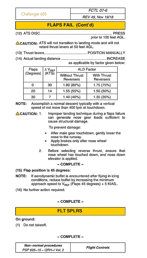
Source: Bombardier Inc., Bombardier Challenger 605 Quick Reference Handbook, Non-normal procedures, Volume 2, Revision 49 (19 November 2018).
Appendix B – Occurrence landing overview based on flight data recorder data
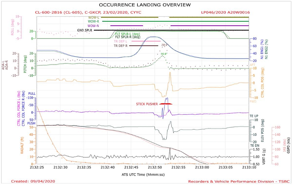
Source: TSB
Appendix C – Transport Canada service difficulty reports involving flap flexible drive shafts on Challenger series aircraft
1986061700052 – Challenger 600 (CL600 1A11)
Part number: 2022264-6 (600-93000-61)
Problem description:
FLAPS FAILED AT 43 DEGREES, SEVERAL ATTEMPTS WERE MADE TO RESET THE FLAP SYS PER CANADAIR MAINT MANUAL, ALL OF WHICH FAILED. VOLTAGE WAS CHCD AT THE POWER DRIVE UNIT AND FOUND TO BE CORRECT. THE PDU WAS REMOVED, AND AN ATTEMPT WAS MADE TO CRANK THE FLAPS MANUALLY AT THIS POINT IT WAS FOUND THAT THE DRIVE SHAFT WAS SEIZED. THE SHAFT WAS REMOVED AND REPLACED. A/C WAS RETURNED TO SERVICE. PROBABLE CAUSE WAS LACK OF LUBRICATION, AT THIS TIME THERE IS NO REQUIREMENT TO LUBRICATE THE FLEXSHAFTS.
19900121300118 – Challenger 600 (CL600 1A11)
Part number: 2022264-10 (600-63000-69)
Problem description:
FOUND OUTER FLAP BRAKE CABLE HOUSING LOOSE AT END FITTING. REPLACED CABLE.
2001091100185 – Challenger 604 (CL600 2B16)
Part number: 2022264-8 (600-93000-65)
Problem description:
DURING OPS CHECK OF THE FLAPS, A FLAP FAIL MESSAGE APPEARED ON THE EICAS. PHYSICAL INSPECTION FOUND RIGHT OUTBOARD FLAP IN 45 DEGREE DOWN POSITION AND OTHER FLAP SEGMENTS APPROACHING 30 DEGREE DETENT. INVESTIGATION FOUND RIGHT FLAP DRIVE NR8 SWAGE END PULED OUT OF THE FLEX DRIVE HOUSING CAUSING FLAP DRIVE CABLE TO MOVE OUT OF FLAP ACTUATOR. FERRULE END DOES NOT APPEAR TO HAVE BEEN CRIMPED.
2020020227014 – Challenger 605 (CL600-2B16)
Part number: 2022264-7 (600-93000-63)
Problem description:
FLAP FAIL MESSAGE RECEIVED ON APPROACH. FLAPLESS LANDING PROCEDURE EXECUTED PER QRH. MAINTENANCE INVESTIGATION REVEALED THE FLAP FLEXIBKLE DRIVE SHAFT ON THE INNER LEFT HAND WING HAD SHEARED AT THE OUTER SWAGED FITTING. INSPECTION OF THE FLAP FLEXIBLE DRIVE SHAFT SHOWS IT TO BE DRY OF LUVRICATION AND EXHIBITING SIGNS OF SIGNIFICANT CORROSION, MOST MARKEDLY AT POINT OF FAILURE. TLMC HAS ONE MAINTENANCE EVENT CONCERNING THE FLAP SYSTEM FELXIBLE DRIVE SHAFT, TLMC ITEM 27-50-00-202 (27-53-07-220-801), DETAILED INSPECTION OF FLEXIBLE DRIVE SHAFT ASSEMBLY. THIS EVENT HAS A 2400 FH THRESHOLD AND A 2400 FH REPEAT REQUIREMENT. AIRCRAFT TOTAL TIME AT TIME OF FAILURE 1699.3.
Appendix D – Bombardier Challenger 605 full stop landing procedure
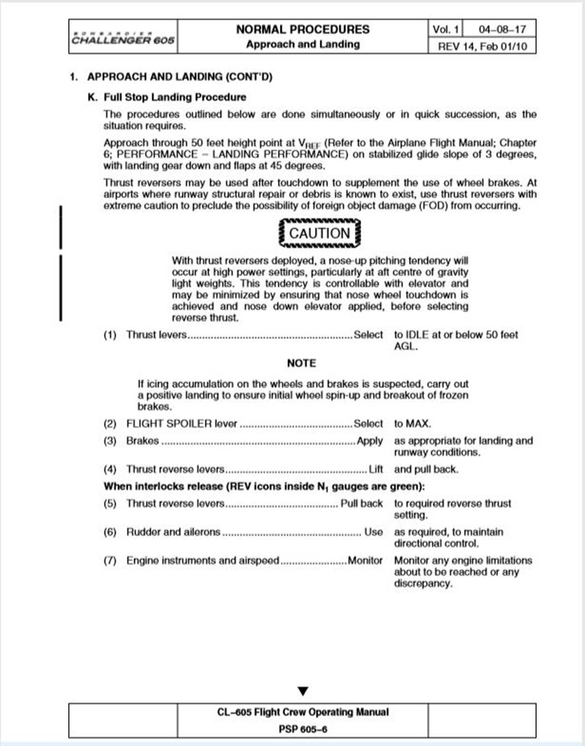
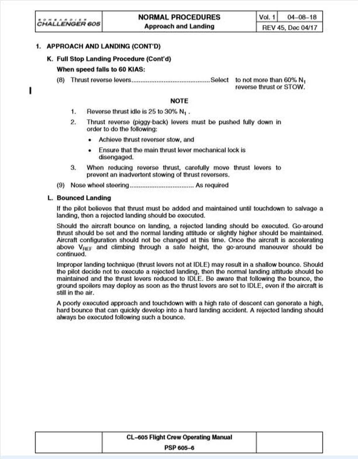
Source: Bombardier Inc.
Appendix E – Bombardier CRJ maintenance task card no. 000-27-580-103
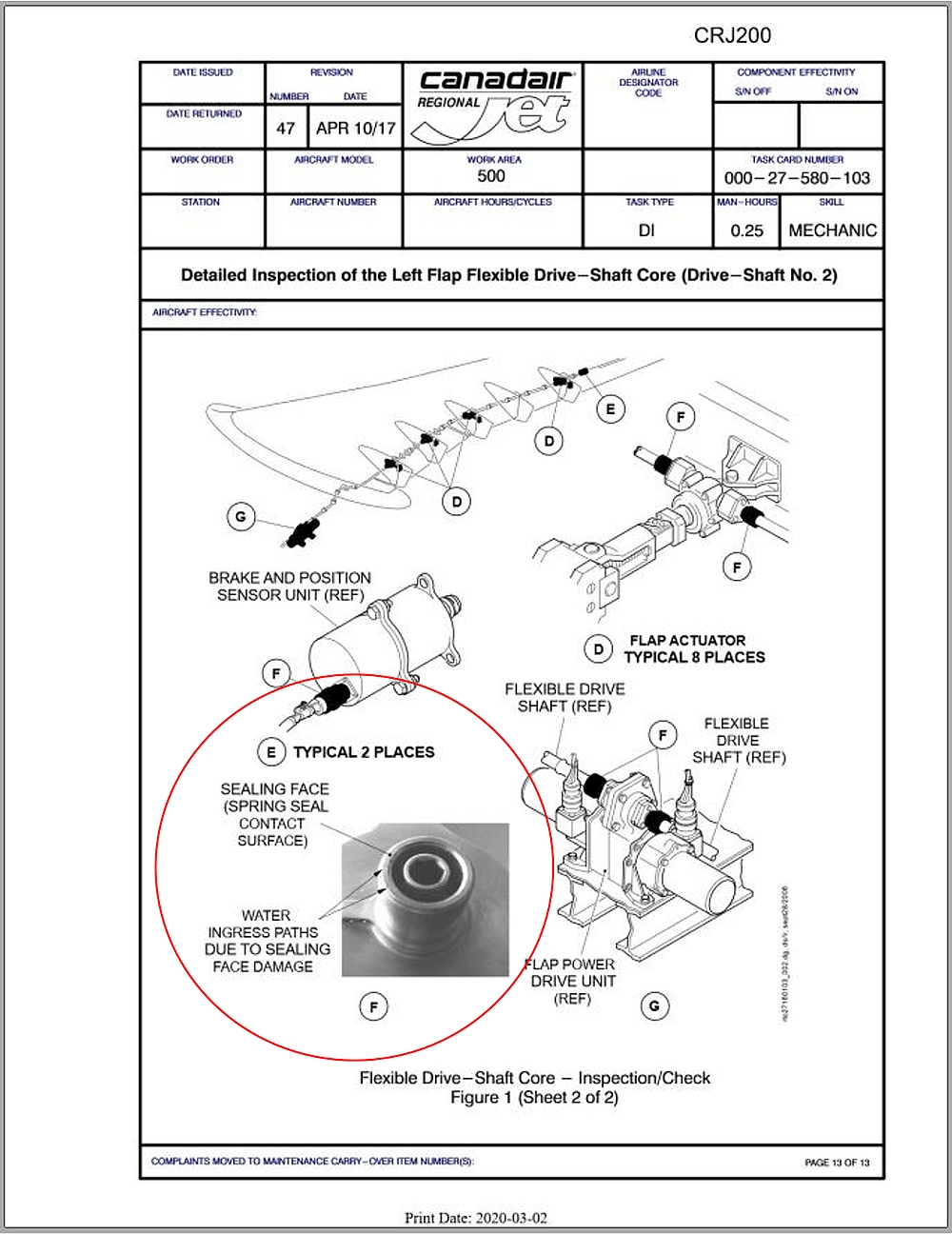
Source: Bombardier Inc., with TSB annotations