Engine failure and collision with terrain
Kestrel Helicopters Ltd.
Hughes Helicopters, Inc. 369D (helicopter), C-GJLC
Port McNeill Aerodrome, British Columbia, 25 NM ESE
The Transportation Safety Board of Canada (TSB) investigated this occurrence for the purpose of advancing transportation safety. It is not the function of the Board to assign fault or determine civil or criminal liability. This report is not created for use in the context of legal, disciplinary or other proceedings. See Ownership and use of content. Masculine pronouns and position titles may be used to signify all genders to comply with the Canadian Transportation Accident Investigation and Safety Board Act (S.C. 1989, c. 3).
Summary
On 06 April 2022, the Kestrel Helicopters Ltd. Hughes Helicopters, Inc. 369D helicopter (registration C-GJLC, serial number 1129D) was conducting slinging operations under visual flight rules 25 nautical miles east-southeast of Port McNeill Aerodrome, British Columbia, with only the pilot on board. Shortly after releasing a bundle of cedar blocks, the aircraft experienced an engine failure. The pilot broadcasted a distress call on the radio at 0909 Pacific Daylight Time and, within a few seconds, the helicopter collided with terrain. The ground crew that was working with the pilot arrived at the accident site approximately 10 minutes thereafter. The pilot was fatally injured. The helicopter was substantially damaged. The 406 MHz emergency locator transmitter activated, and the signal was received by the Joint Rescue Coordination Centre in Victoria, British Columbia. A Canadian Armed Forces search and rescue helicopter and the Royal Canadian Mounted Police both responded to the scene.
1.0 Factual information
1.1 History of the flight
On 06 April 2022, the Kestrel Helicopters Ltd. Hughes Helicopters, Inc. 369D was scheduled to carry out slinging operations at a location in the Naka Creek region, approximately 25 nautical miles (NM) east-southeast of Port McNeill Aerodrome (CAT5), British Columbia (BC). At 0645,Footnote 1 the helicopter departed the operator’s base in Parksville, BC, on a visual flight rules (VFR) flight with only the pilot on board. He was seated in the left seat.Footnote 2
Flight tracking information indicates that the helicopter landed at 0749, approximately 4 NM south of the accident site. It then departed for a 2nd flight at 0754 and landed at the staging area at 0814.
At the staging area, the pilot met with the 4 members of the ground crew for a safety briefing in preparation for the day’s work, which would involve transporting cedar blocks. The ground crew then drove to the location of the cut block, where they would be working, and the pilot prepared the helicopter for slinging by removing the left door and attaching a 180-foot longline.
At approximately 0900, the helicopter departed the staging area to sling bundles of cedar blocks. After picking up and releasing the 2nd load of blocks, the helicopter experienced an engine failure. The pilot broadcasted a distress call on the radio at 0909 and within a few seconds the helicopter collided with the terrain.
After hearing the pilot’s distress call on the radio, the ground crew drove to the accident site and arrived approximately 10 minutes after the accident. The helicopter was found approximately 200 feet from the area where the cedar blocks had been placed. The pilot was fatally injured. The helicopter was substantially damaged.
The 406 MHz emergency locator transmitter automatically activated on impact, and the signal was received by the Joint Rescue Coordination Centre in Victoria, BC. A Canadian Armed Forces search and rescue helicopter and the Royal Canadian Mounted Police both responded to the scene.
1.2 Injuries to persons
The pilot was alone on board. Table 1 outlines the degree of injuries received.
| Degree of injury | Crew | Passengers | Persons not on board the aircraft | Total by injury |
|---|---|---|---|---|
| Fatal | 1 | – | – | 1 |
| Serious | 0 | – | – | 0 |
| Minor | 0 | – | – | 0 |
| Total injured | 1 | – | – | 1 |
1.3 Damage to aircraft
The helicopter was substantially damaged.
1.4 Other damage
There was no other damage.
1.5 Personnel information
| Pilot licence | Commercial pilot licence - helicopter |
|---|---|
| Medical expiry date | 01 December 2022 |
| Total flying hours | approximately 13 000 |
| Flight hours on type | approximately 11 000 |
| Flight hours in the 24 hours before the occurrence | 4.5 |
| Flight hours in the 7 days before the occurrence | 10.9 |
| Flight hours in the 90 days before the occurrence | 72.3 |
| Flight hours on type in the 90 days before the occurrence | 72.3 |
| Hours on duty before the occurrence | 3.5 |
| Hours off duty before the work period | 16 |
The pilot held the appropriate licence and rating for the flight in accordance with existing regulations. He held a commercial pilot licence – helicopter and was type-rated on the occurrence helicopter and 5 other helicopters. He had experience operating in the area and had accumulated approximately 6000 hours slinging cedar blocks.
The pilot had been employed by Kestrel Helicopters Ltd. since 2010. He had completed annual helicopter training in April 2021, which covered engine failures while in a hover and various autorotation practices, such as straight ahead, 180°, 360°, and surprise autorotations. In addition, he had completed training for pilot decision making, human factors, and emergency procedures.
The pilot had been off duty for 16 hours before the beginning of the work period on the day of the occurrence, and he had been on duty for 3.5 hours before the occurrence. According to the information gathered, there was no indication that fatigue contributed to the occurrence.
1.6 Aircraft information
| Manufacturer | Hughes Helicopters, Inc. |
|---|---|
| Type, model, and registration | 369D, C-GJLC |
| Year of manufacture | 1981 |
| Serial number | 1129D |
| Certificate of airworthiness | 27 March 2002 |
| Total airframe time | 11 884.4 hours |
| Engine type (number of engines) | Rolls-Royce 250-C20B (1) |
| Rotor type (number of blades) | Fully articulated main rotor system (5) |
| Maximum allowable take-off weight | 3000 lb (1361 kg) |
| Recommended fuel type(s) | Jet A, Jet A-1, Jet B |
| Fuel type used | Jet A |
* MD Helicopters, LLC. currently holds the type certificate for the aircraft type.
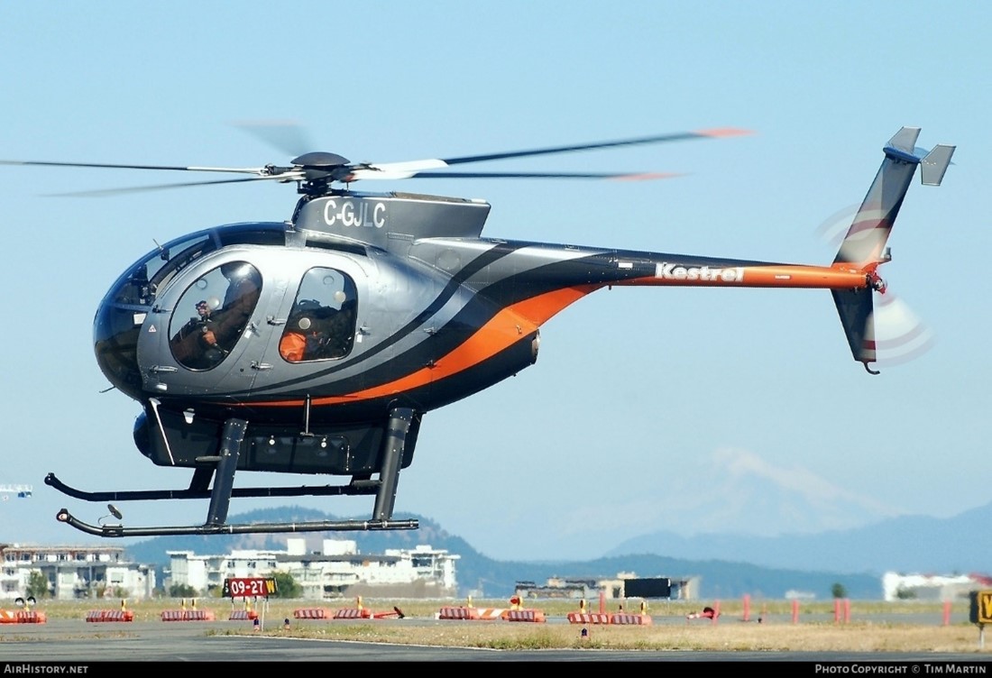
The Hughes Helicopters, Inc. 369D, a model in the MD 500 series, is a light utility helicopter (Figure 1) that is powered by a Rolls-Royce 250-C20BFootnote 3 turbine engine.
Following the last 150-hour engine inspection before the occurrence, which had been conducted on 18 March 2022, the compressor case halves were replaced due to normal wear on the lining.
At the time of the occurrence, the compressor on the occurrence aircraft had 15 404 hours total time in service and was due for overhaul in 353.4 hours.Footnote 4 The sixth stage compressor wheel, which has no life limit, had 6646.6 hours total time in service.
The most recent maintenance work, which involved the removal of the cargo pod, had been performed on 05 April 2022.
There were no recorded outstanding defects at the time of the occurrence. In addition, the aircraft’s weight and centre of gravity were within the prescribed limits.
1.6.1 Helicopter performance and height velocity diagram
The MD 500D Rotorcraft Flight Manual describes the helicopter’s limitations with respect to its height and indicated airspeed at a given time. The manual presents these parameters in a chart (Figure 2) and explains in a caution note (Figure 3) that the cross-hatched areas represent height-indicated airspeed combinations that would make a successful autorotation landing difficult for the pilot to perform. It also states that operation within the cross-hatched area, while not prohibited, should be avoided.Footnote 5
![Height velocity diagram for the 369D (Source: MD Helicopters, LLC., MD 500D Rotorcraft Flight Manual [Model 369D], Revision 13 [21 July 2016], Section V: Performance Data, p. 5-21.)](/sites/default/files/eng/rapports-reports/aviation/2022/a22p0023/images/a22p0023-figure-02.jpg)
![Caution note explaining the cross-hatched areas of the height velocity diagram (Source: MD Helicopters, LLC., MD 500D Rotorcraft Flight Manual [Model 369D], Revision 13 [21 July 2016], Section V: Performance Data, p. 5-20.)](/sites/default/files/eng/rapports-reports/aviation/2022/a22p0023/images/a22p0023-figure-03.jpg)
At the time of the engine failure, the occurrence helicopter was likely at a height of 200 to 300 feet above ground level, with little to no forward airspeed.
1.7 Meteorological information
The graphic area forecast issued at 0425 and valid at 0500 on 06 April indicated scattered clouds between 2000 and 4000 feet above sea level, visibility of more than 6 statute miles (SM), and localized visibility of 1 SM in mist.
The nearest aviation weather reporting station is 40 NM northwest of the occurrence site, at Port Hardy Airport (CYZT), BC. The aerodrome routine meteorological report (METAR) for CYZT issued at 0700 indicated the following:
- Winds from 120° true at 14 knots, gusting to 20 knots
- Visibility of 20 SM
- Scattered clouds at 900 feet above ground level and broken ceiling at 10 000 feet
- Temperature 4 °C, dew point 2 °C
- Altimeter setting 30.38 inches of mercury
The Fanny Island weather station is situated 15 NM east of the occurrence location, at sea level. At 0700, the station reported winds from the east-southeast at 10 knots, a temperature of 4 °C, and a dew point of 2 °C. At 0800, the report was as follows: winds from the southeast at 8 knots, temperature 3 °C, and dew point 1 °C.
Weather was not considered to be a factor in this occurrence.
1.8 Aids to navigation
Not applicable.
1.9 Communications
There were no known communication difficulties.
1.10 Aerodrome information
Not applicable.
1.11 Flight recorders
The aircraft was not equipped with a flight data recorder or a cockpit voice recorder, nor was either required by regulation.
The aircraft was equipped with a transceiver used for flight following. No data is stored in the unit itself; all available data is transmitted to a central server. The data retrieved from the server provided flight track information about the first 2 flights of the day; however, because the flight tracker had been disabled before the occurrence flight,Footnote 6 there was no flight track data available for that flight.
1.12 Wreckage and impact information
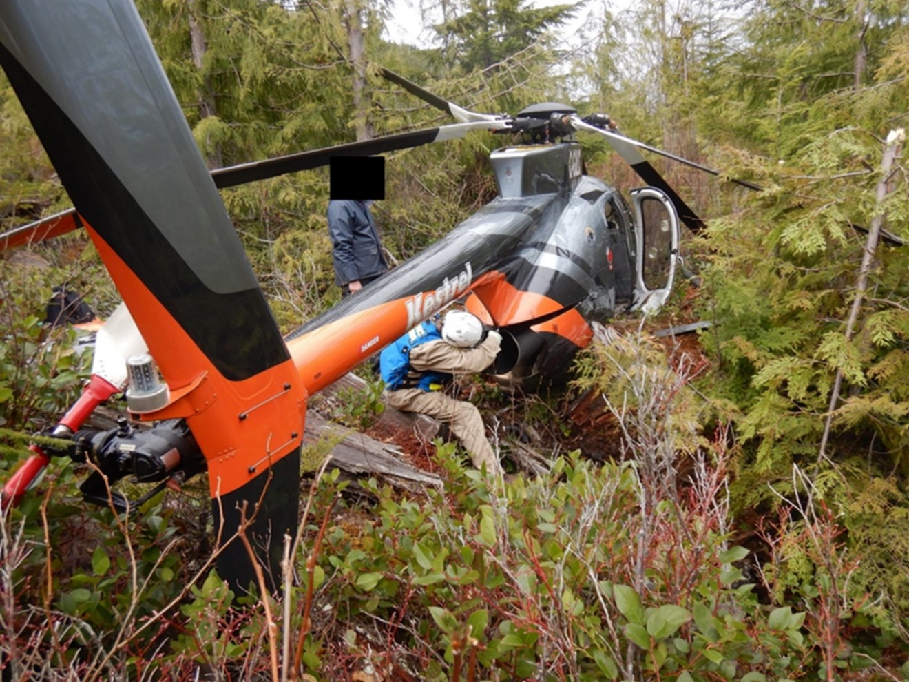
During the occurrence, the helicopter crashed into a wooded area (Figure 4), in an upright attitude and with no horizontal speed.
Following the impact, the tail boom remained straight; there was no sign of it having been struck by a main rotor blade. Both forward and aft struts of the landing gear were spread. A detailed examination of the aircraft showed that while both forward struts of the landing gear remained straight and intact, their connections with the dampers had broken. The rear left strut had fractured in its middle, and the rear right strut had separated from its connection with the fuselage.
The seat box underneath the seat pan was deformed, with the seat panel (the top panel of the seat box) compressed downward. The forward face of the seat box had also sustained severe crushing damage in a downward direction. The outboard and inboard faces had also been severely crushed in a downward direction, though to a lesser extent.
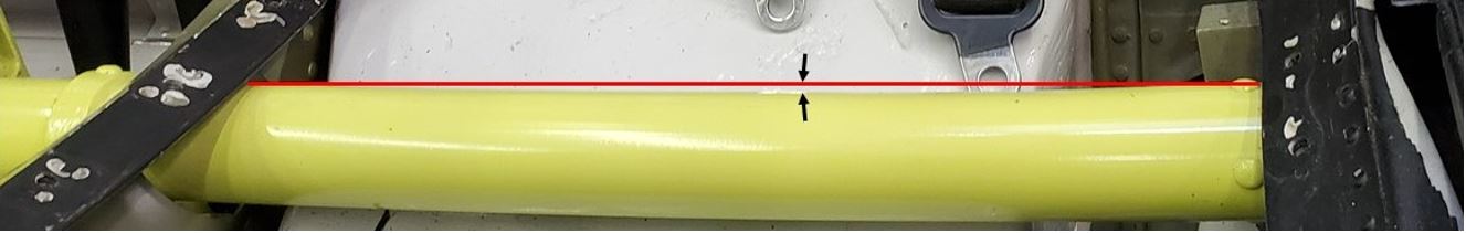
On the pilot’s seat panel, a couple of fastener holes were deformed and had become elliptical. A dent line, with yellow paint transfer on it, was noted across the width of the seat panel. In addition, the top of the cyclic control stick, which is a plastic box with a few control buttons, had been broken during the crash.
The collective control torque tube was located directly underneath the pilot’s seat panel and ran through the 2 side faces of the seat box of the pilot seat. The collective control torque tube was supported at 2 points with bearings, supporting brackets, and fittings, which were mounted on solid or stiffened parts of the structure. The collective control torque tube was found to have been deformed as a result of a downward force.
The damage to the belly of the fuselage appeared to be uneven, likely due to impact with uneven terrain. The section aft of the passenger cabin showed minimal crushing damage. However, the section between the forward and aft landing gear struts had been bent by the impact, and the section underneath the cockpit was severely crushed.
The longline remained attached to the belly of the helicopter, and the hook at the end was found approximately 40 feet from the 2 loads of cedar blocks. The longline was slack and in a relatively straight line leading away from the helicopter wreckage.
Both the markings on the trees surrounding the helicopter and the main rotor blade damage were consistent with low rotational energy at impact.
1.12.1 Engine compressor examination
1.12.1.1 Sixth stage compressor wheel fracture and failure
The compressor assembly of the engine (Figure 5) was disassembled and examined at the TSB Engineering Laboratory in Ottawa, Ontario.
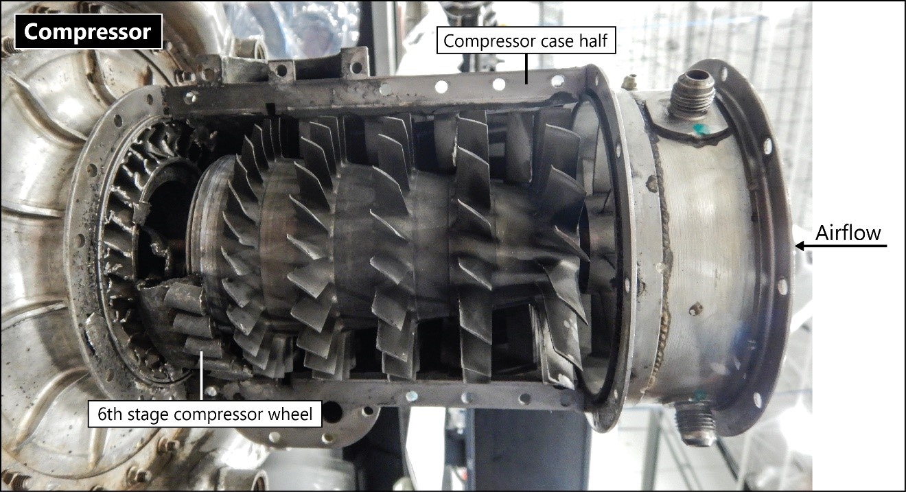
During this examination, it was determined that the compressor blades and guide vanes of the compressor assembly were damaged. In particular the compressor blades on the first through fifth stage compressor wheels were damaged but still in place. On the sixth stage compressor wheel, all of the blades were fractured or curled over. The guide vanes on the first through fourth stages were bent and damaged but still in place, whereas all of the guide vanes on the fifth and sixth stages were either liberated or bent over completely in the direction of engine rotation. There was no obvious damage noted on the outside of the case halves. The sixth stage compressor wheel was broken and wedged within the assembly. Gross plastic deformation of the wheel was also noted.
The tie bolt, which holds the compressor assembly together, had failed at the aft end. Visual examinations of the bearings were completed as the compressor was disassembled, and all bearings rotated freely with no obvious damage observed.
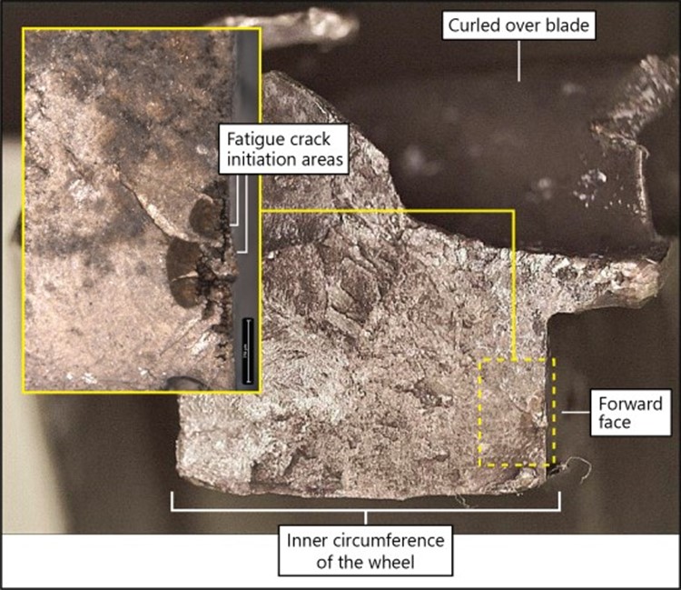
The sixth stage compressor wheel (part number 23057116, serial number KR59007) was extracted from the compressor assembly and found to have fractured into 2 pieces, with no pieces missing (Figure 6).
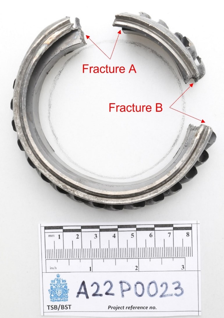
One of these fractures (fracture A) was caused by multiple fatigue cracks that had propagated inward from the forward face of the wheel. This cracking appears to have developed at shrinkage voids,Footnote 7 some of which appeared to be partially open to the surface, located on the forward face, closer to the inner circumference of the wheel (Figure 7). The final separation at this fracture was due to overstress. The 2nd fracture (fracture B) was caused entirely by overstress.
1.12.1.2 Sixth stage compressor wheel metal composition
According to the manufacturer, at the time of the sixth stage compressor wheel’s manufacture, the wheel was made from AMSFootnote 8 5355 – 17-4 PHFootnote 9 steel and expected to have a hardness in the range of 36 to 43 HRC.Footnote 10 The TSB laboratory inspection determined that the measured hardness of the failed sixth stage compressor wheel was 40.3 ± 0.6 HRC and, therefore, within the expected range. The inspection also determined that, with the exception of the shrinkage voids, the chemistry and microstructure of the failed component were also consistent with AMS 5355 – 17-4 PH steel. The occurrence part was manufactured by casting followed by finish machining.
1.13 Medical and pathological information
According to information gathered during the investigation, there was no indication that the pilot’s performance was affected by medical, physiological, or pathological factors.
1.14 Fire
There was no indication of fire either before or after the occurrence.
1.15 Survival aspects
The pilot was wearing a 4-point safety belt and a helmet at the time of the accident.
The 406 MHz emergency locator transmitter transmitted a signal that was received by Joint Rescue Coordination Centre in Victoria, BC.
1.15.1 Protective structures
The magnitude of the impact force felt by a helicopter occupant during a crash depends on both the impact energy of the helicopter and how the helicopter’s structures react and absorb the impact energy to lessen the acceleration force. The helicopter’s protective structures, designed to assist with occupant survival in such a crash scenario, consist of 3 systems: the landing gear, the bottom structure of the fuselage, and the seat.
It was observed that the landing gear struts were spread, their dampers were damaged, and the bottom of the fuselage was crushed. Damage to these parts of the aircraft is normally the result of their absorption of part of the impact energy during the crash. When these structures absorb part of the impact, the acceleration force is attenuated.
The 3rd protective structure, the seat, was partially and unevenly crushed as a result of the occurrence. Per crashworthiness design principles, the seat is typically designed to assume the inertial load during the whole process of its yielding or collapse in order to absorb the impact energy. Because of the relatively small clearance between the seat panel and collective control torque tube, the yielding of the seat structure results in contact between them. As a result, part of the inertial load from the occupant is transferred to the collective control torque tube, as was the case in this occurrence (Figure 8).
A calculation based on the structural damage to the seat and collective control torque tube of the occurrence helicopter indicates that the occupant experienced an estimated vertical acceleration force greater than 53 g.Footnote 11
Under normal conditions, an object is at a 1 g force state. When the weight of that object is doubled or tripled due to a sudden change in state or momentum, the object will have a g force of 2 or 3 respectively, and so on. Studies conducted by the Federal Aviation Administration of the United States and the National Aeronautics and Space Administration concluded that g force levels beyond 27 will result in serious injury and could potentially be fatal.Footnote 12
1.16 Tests and research
1.16.1 TSB laboratory reports
The TSB completed the following laboratory reports in support of this investigation:
- LP035/2022 – NVM Recovery – Instruments
- LP043/2022 – NVM Recovery – iPhone
- LP055/2022 – Compressor Examination and Failure Analysis
- LP059/2022 – Occupant Survivability Analysis
1.17 Organizational and management information
Kestrel Helicopters Ltd. is a privately owned company that conducts VFR air taxi and longline operations in accordance with Canadian Aviation Regulations subparts 702 and 703. At the time of the occurrence, the company’s fleet consisted of 5 helicopters: three 369Ds, one AS 350, and one Bell 204B. The company employs 8 people and has a main base located in Parksville, BC. It operates primarily in western Canada. The company is also a Transport Canada–approved maintenance organization with ratings for all non-specialized work for the types of aircraft it operates.
The occurrence flight was on a VFR flight itinerary, with the intended route indicated on a wall map at the operator’s base.
1.18 Additional information
1.18.1 Metal porosity
During the metal manufacturing process, porosity, or the formation of pores, can occur in a die casting either when air or gas is trapped in the metal as it solidifies or when the metal shrinks unevenly. This causes holes and voids in the metal that make it vulnerable to structural deficiencies.
Irregularities caused by porosity cannot be detected through visual inspections. Although porosity can be located by performing a computer tomography (CT) scan, CT scans are not required during the regular compressor overhaul process, nor is it industry standard to perform these scans during the production process.
An X-ray inspection was conducted on the occurrence sixth stage compressor wheel after production in accordance with the engineering drawing for this part. The results were found to be within the specified limits and the part was released into service. However, an irregularity of the size found in the occurrence sixth stage compressor wheel is not detectable using this industry standard X-ray inspection process.
The compressor wheel underwent a visual inspection and a fluorescent penetrant inspection during the compressor overhaul on 02 January 2014. At the time, it had 3524.8 hours total time in service. The results were within its prescribed tolerances.
1.18.2 Previous sixth stage compressor wheel events and changes to the manufacturing process
From January 1986 through January 2002, 9550 sixth stage compressor wheels were cast and shipped to the engine manufacturer. In addition to this occurrence, the manufacturer is aware of 2 other failures of sixth stage compressor wheels from the same supplier, one of which had the same part number as the occurrence wheel. Those failures occurred in March 2019 and February 1989, and both were found to have been due to fatigue cracks originating at shrinkage voids near the inner circumference of the wheel. Footnote 13
However, changes have been made to the design of the sixth stage compressor wheel since the manufacture of the occurrence wheel in 2001 and the 2 other failed wheels. Most recently, in 2007, the design was changed such that the part can be fully machined from heat-treated wrought iron Custom 450 (C450) bar stock. C450 is a custom stainless-steel alloy that provides improved mechanical strength and fatigue properties as compared to the cast sixth stage compressor wheels.Footnote 14 The engine manufacturer issued a Commercial Service Letter on 01 March 2007 to inform its customers of the release of these new compressor wheels.
1.18.3 Cedar block logging
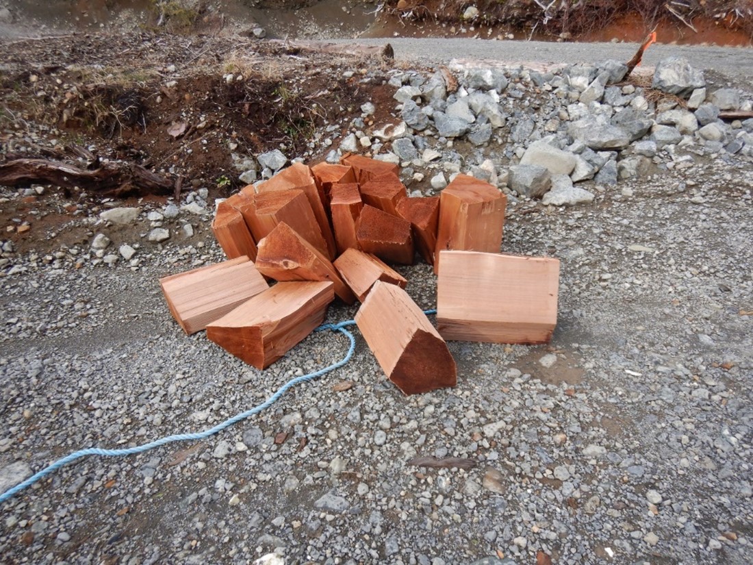
Cedar blocks are cut from dead snags, residual logs too short to be taken out in prime logging, and cedar stumps. They are bound together with rope into bundles that weigh between 700 and 1200 pounds.
The occurrence ground crew estimated that the 2 bundles released by the pilot before the helicopter’s collision with terrain each weighed approximately 800 pounds (Figure 9).
2.0 Analysis
The occurrence pilot held the appropriate licence and ratings for the occurrence flight, and there was no indication that his performance had been degraded by medical, physiological, or pathological factors. Weather conditions at the time of the occurrence were suitable for visual flight rules flight.
This analysis will discuss the engine failure that the helicopter experienced while conducting slinging operations. It will focus on the cause of this engine failure, the possibility of autorotation, the survivability aspects of the occurrence, and the risks associated with longline operations.
2.1 Sixth stage compressor wheel failure
The hardness of the failed sixth stage compressor wheel in the occurrence helicopter’s engine compressor was measured at the TSB laboratory. Its hardness, which was 40.3 ± 0.6 HRC, was within the normal range. The chemistry and microstructure of the failed component were also analysed at the TSB laboratory, and they were deemed to be consistent with AMS 5355 – 17-4 PH steel, with the exception of the shrinkage voids.
During the manufacturing process for metal components of an engine, porosity can occur, leaving small holes or voids in the metal. A computer tomography (CT) scan of the metal part can locate this defect, which cannot be detected through a regular visual inspection. However, CT scans are not required during the regular compressor overhaul process, nor is it industry standard to perform these scans during the production process.
An X-ray inspection was conducted on the occurrence sixth stage compressor wheel after production in accordance with the engineering drawing for this part. The results were found to be within the specified limits and the part was released into service.
The compressor wheel underwent a visual inspection and a fluorescent penetrant inspection during the compressor overhaul and was found to be within its prescribed tolerances.
The compressor case halves were replaced on 18 March 2022 after normal wear had been found during a routine inspection. Given the location of the origin of the fatigue crack, near the inner circumference of the sixth stage compressor wheel, this crack could not have been visible during the visual inspection that had been completed when the case halves were replaced.
Finding as to causes and contributing factors
For undetermined reasons, shrinkage voids developed near the inner circumference of the engine’s sixth stage compressor wheel during the manufacturing process and went undetected using the existing inspection methods.
The sixth stage compressor wheel separated into 2 pieces, resulting from 2 fractures. One of these fractures was caused by multiple fatigue cracks that had propagated inward from the forward face of the wheel. This cracking appears to have developed at shrinkage voids, some of which appeared to be partially open to the surface, located on the forward face, closer to the inner circumference of the wheel. The final separation at this fracture was due to overstress. The other fracture was entirely due to overstress.
Finding as to causes and contributing factors
The sixth stage compressor wheel eventually failed when 2 separate fractures, one due to fatigue caused by shrinkage voids and the other due to overstress, occurred. The failure of the sixth stage compressor wheel resulted in a catastrophic engine failure.
It was determined that the blade failures in the compressor assembly had been caused by overstress and that the tie bolt failed in torsional overstress. These failures were incidental to the fatigue failure of the sixth stage compressor wheel.
2.2 Autorotation
A few moments before the engine failure, the helicopter had released the 2nd of 2 loads of cedar blocks. The hook at the end of the longline was found 40 feet from the area where the cedar blocks had been placed, and the 180-foot longline was found attached to the helicopter and lying in a relatively straight line. This indicates that the helicopter was likely at an approximate height of 200 to 300 feet above ground level with little to no forward airspeed when the engine failure occurred.
According to the MD 500D Rotorcraft Flight Manual, the combination of the helicopter’s height and airspeed would have made a successful autorotation landing more difficult.
Finding as to causes and contributing factors
The engine failure occurred shortly after the helicopter had released a load of cedar blocks from a 180-foot longline. Therefore, the helicopter likely had insufficient height and forward speed to conduct a successful autorotation. As a result, the helicopter impacted the terrain with significant vertical speed, causing substantial damage to the helicopter.
2.3 Survivability
2.3.1 Energy
Given that the helicopter crashed into wooded terrain in an upright attitude and without horizontal speed, an analysis of the survivability of the maximum vertical acceleration force (or impact force) that the pilot sustained as a result of the crash was performed.
A pilot’s survivability depends not only on the helicopter’s impact energy, but also on the degree to which the helicopter’s structures absorb this impact energy and attenuate the acceleration force. The helicopter’s landing gear, the bottom structure of its fuselage, and its seat are 3 protective structures designed to increase occupant survivability in crash scenarios such as the one encountered by the occurrence pilot.
The investigation was able to determine that the landing gear struts, which were spread and damaged, and the bottom of the fuselage, which had been crushed, had absorbed part of the impact energy, attenuated the acceleration force in the occurrence, and therefore performed according to design.
However, the seat, which is designed to assume the inertial load during its yielding or collapse in order to absorb the energy of the impact, was partially and unevenly crushed. The relatively small clearance between the seat panel and collective control torque tube resulted in contact between these 2 components, and, as a result, part of the inertial load from the pilot was transferred to the collective control torque tube.
Based on an examination of the structural damage to the helicopter’s seat and collective control torque tube, investigators estimated that the vertical acceleration force experienced by the occurrence pilot was greater than 53 g. Studies conducted by the Federal Aviation Administration of the United States and the National Aeronautics and Space Administration concluded that g force levels beyond 27 will result in serious injury and could potentially be fatal.
Finding as to causes and contributing factors
The helicopter pilot was subjected to a minimum vertical acceleration force of 53 g on impact, resulting in fatal injuries.
2.4 Single-engine helicopter longline operations
The cross-hatched areas on the height velocity diagram in the 369D flight manual show combinations of airspeed and height above ground that should be avoided because it would be difficult to perform a successful autorotation landing.
Longline operations whereby a helicopter picks up and drops off slung loads necessarily involve the helicopter entering these particular height-airspeed combinations often, given that it must operate at heights equal to or slightly higher than the length of the longline, with little to no airspeed, to successfully complete the task. These factors increase the risk of the pilot being unable to complete a successful landing after an engine failure.
Finding as to risk
If single-engine helicopters routinely operate with unsafe height-airspeed combinations, the likelihood of a successful landing after an engine failure is significantly reduced, increasing the risk of injury or death.
3.0 Findings
3.1 Findings as to causes and contributing factors
These are conditions, acts or safety deficiencies that were found to have caused or contributed to this occurrence.
- For undetermined reasons, shrinkage voids developed near the inner circumference of the engine’s sixth stage compressor wheel during the manufacturing process and went undetected using the existing inspection methods.
- The sixth stage compressor wheel eventually failed when 2 separate fractures, one due to fatigue caused by shrinkage voids and the other due to overstress, occurred. The failure of the sixth stage compressor wheel resulted in a catastrophic engine failure.
- The engine failure occurred shortly after the helicopter had released a load of cedar blocks from a 180-foot longline. Therefore, the helicopter likely had insufficient height and forward speed to conduct a successful autorotation. As a result, the helicopter impacted the terrain with significant vertical speed, causing substantial damage to the helicopter.
- The helicopter pilot was subjected to a minimum vertical acceleration force of 53 g on impact, resulting in fatal injuries.
3.2 Findings as to risk
These are conditions, unsafe acts or safety deficiencies that were found not to be a factor in this occurrence but could have adverse consequences in future occurrences.
- If single-engine helicopters routinely operate with unsafe height-airspeed combinations, the likelihood of a successful landing after an engine failure is significantly reduced, increasing the risk of injury or death.
4.0 Safety action
4.1 Safety action taken
4.1.1 Rolls-Royce Corporation
On 18 May 2023, the engine manufacturer re-issued Commercial Service Letter 1255, which includes a recommendation that its customers convert the compressor to the new wheel design during the next overhaul.
This report concludes the Transportation Safety Board of Canada’s investigation into this occurrence. The Board authorized the release of this report on . It was first officially released on .
Correction
Following the publication of the investigation report, certain inconsistencies were identified between the TSB laboratory report and the final investigation report.
In section 1.12.1.1 Sixth stage compressor wheel fracture and failure, the sentence “This cracking developed at shrinkage voids that were partially open to the edge, located on the forward face, closer to the inner circumference of the wheel (Figure 7).” was changed to “This cracking appears to have developed at shrinkage voids, some of which appeared to be partially open to the surface, located on the forward face, closer to the inner circumference of the wheel (Figure 7).”
In section 2.1 Sixth stage compressor wheel failure, the sentence “This cracking developed at shrinkage voids that were partially open to the edge, located on the forward face, closer to the inner circumference of the wheel.” was changed to “This cracking appears to have developed at shrinkage voids, some of which appeared to be partially open to the surface, located on the forward face, closer to the inner circumference of the wheel.”
This correction was approved by the Board on ; the corrected version of the report was released on .