Engine room fire
Container vessel MOL Prestige
146 nautical miles SSW of Haida Gwaii, British Columbia
The Transportation Safety Board of Canada (TSB) investigated this occurrence for the purpose of advancing transportation safety. It is not the function of the Board to assign fault or determine civil or criminal liability. This report is not created for use in the context of legal, disciplinary or other proceedings. See Ownership and use of content. Masculine pronouns and position titles may be used to signify all genders to comply with the Canadian Transportation Accident Investigation and Safety Board Act (S.C. 1989, c. 3).
Executive summary
On 31 January 2018, a fire broke out in the engine room of the container vessel MOL Prestige while the vessel was at sea 146 nautical miles south-southwest of Haida Gwaii, British Columbia (BC). There were 22 crew and 1 supernumerary on board at the time. The fire was eventually extinguished. Five of the crew members were seriously injured. A Royal Canadian Air Force helicopter evacuated 2 of the crew members to hospital in the Village of Queen Charlotte, BC. The Canadian Coast Guard ship Sir Wilfrid Laurier assisted until a salvage tug arrived and towed the disabled vessel to Seattle, Washington, United States.
The investigation identified a number of safety deficiencies described below.
Engine room maintenance and practices
The investigation identified maintenance-related issues in the engine room of the MOL Prestige. The level indicators on the settling and service tanks were inoperative and the engineers had to climb onto the tanks and unbolt a blind flange in order to sound the tank. Over time, the blind flange was left off the level indicator pipe for the settling tank. As well, at some point, the high-temperature alarm on the settling tank had been set at 30 °C above the safe maximum temperature. This meant that any water entering the settling tank might be subject to frothover because oil in the tank above 100 °C would cause any water in the tank, or added to the tank, to boil instantly. The high temperature in the settling tank, in conjunction with the open level indicator pipe on the settling tank, created unsafe conditions that allowed frothover to expunge oil and fumes out of the tank and the steam explosion, which resulted in the fire.
The responsibility for ensuring that equipment in the engine room is maintained safely and that engine room practices are safe is shared by vessel management and crew. In the case of the MOL Prestige, the year before the occurrence, the technical management of the vessel had changed and a new reporting system had been introduced. During this period of change, issues that had been identified by the engine room crew went unaddressed and, as a result, because the engine room equipment was not maintained as required by company procedures and the manufacturer’s specification, some of the engine room equipment presented hazards.
If those responsible for ensuring an engine room is maintained sufficiently do not work together to mitigate hazards (leaks, broken equipment, adaptations) in a timely and efficient manner, there is a risk that engine room equipment will fail, leading to accidents.
Egress and evacuation from engine room
Timely egress and evacuation from an engine room is essential in the event of an engine room fire. In this occurrence, the engine room personnel met in the engine control room as the fire began developing, but then became trapped once the fire escalated. A number of factors combined to make egress from the engine control room and subsequent evacuation efforts challenging, placing crew members at risk during the emergency response and prolonging the time that elapsed before egress was possible. During this delay the fire continued to burn unabated.
Cargo vessels constructed after 01 January 2016 must meet regulations set out by The International Convention of Safety of Life at Sea (SOLAS) with respect to escape arrangements from engine control rooms. Although not required for cargo vessels such as the MOL Prestige, which was constructed prior to 01 January 2016, an evacuation analysis of the engine room may have prompted an evaluation of the necessary means of escape from the engine control room, including the placement of the emergency escape breathing devices, the markings required, and the visibility of the exit doors.
If the owners/operators of cargo vessels constructed before 01 January 2016 do not evaluate evacuation routes to ensure that escape arrangements from engine control rooms provide an equivalent level of safety to that required by the current SOLAS regulations, there is a risk that the means of escape provided will be insufficient to support safe and timely egress to a safe position outside machinery spaces.
Emergency preparedness and drills
To respond effectively to a fire, crew must be trained in emergency procedures and must practise using emergency equipment. Drills that are realistic and include varying scenarios help to increase a crew’s preparedness and effectiveness in responding to a fire. The crew on the MOL Prestige had regularly practised drills related to fire in the engine room and rescue from enclosed space, but not all crew members had had the opportunity to practise donning firefighting equipment, and the drills involving fire had not been conducted with realistic scenarios involving unexpected events. The investigation found that the crew had not had the opportunity to practice all of their designated duties and related procedures during drills.
If emergency drills are not routinely practised and evaluated with all of the crew members’ designated duties, or do not include realistic scenarios, there is a risk that the crew will be unprepared in an emergency.
Maintenance of fixed fire suppression systems
The MOL Prestige was fitted with a fixed fire suppression system, but it had leaks in safety-critical units and hoses that went undetected until the system was inspected after the fire. The regulations specify that the system must be able to withstand a minimum bursting pressure and be subjected to an initial pressure test at the time of construction. There is also a requirement to hydraulically test all CO2 cylinders at regular intervals. However, this principle is not extended to include the distribution system, and there is no requirement for a pressure test to be carried out periodically during the life of the vessel. Inspection and testing regimes for CO2 systems must, therefore, contain provisions that will help ensure their continued integrity.
If critical on-board firefighting appliances, such as a fixed fire suppression system, are not maintained according to the manufacturer’s specifications and regulatory requirements, there is a risk that such systems will not function as intended in an emergency.
Safety management
The MOL Prestige had an audited safety management system that included procedures for hazard identification, for checks to engine room equipment, and for record keeping, among other things, but some of the safety issues identified during the investigation were not identified during audits or routine checks. Furthermore, none of the methods for hazard identification provided for by the vessel’s SMS were successful in leading to the timely correction of these issues.
If companies do not establish an effective SMS that encourages crew to identify hazards and that supports the crew in developing safe and timely mitigations, there is a risk that hazardous operating conditions will remain.
1.0 Factual information
1.1 Particulars of the vessel
| Name of vessel | MOL Prestige |
|---|---|
| IMO number | 9321029 |
| Official number | 399812 |
| Port of registry | Singapore |
| Flag | Singapore |
| Type | Container vessel (fully cellular) |
| Gross tonnage | 71 902 |
| Length (registered) | 279.90 m |
| Built | 2006, Koyo Dockyard Co. Ltd., Japan |
| Propulsion | 1 low-speed, 2-stroke diesel engine (62 920 kW) driving one fixed-pitch propeller |
| Cargo (at the time of the occurrence) | 371 reefer containers and 58 dangerous goods containers |
| Draft (at the time of the occurrence) | Forward: 12.5 m Aft: 13.6 m |
| Number of people on board at the time of the occurrence | 22 crew and 1 supernumerary* |
| Registered owners | IS Container Pte. Ltd., Singapore |
| Ship manager | Mitsui O.S.K. Lines |
| Technical managers | Bernhard Schulte Shipmanagement (China) Company Ltd. |
| Classification society | Nippon Kaiji Kyokai (ClassNK) |
* A supernumerary is an individual on board who is not a crew member.
1.2 Description of the vessel
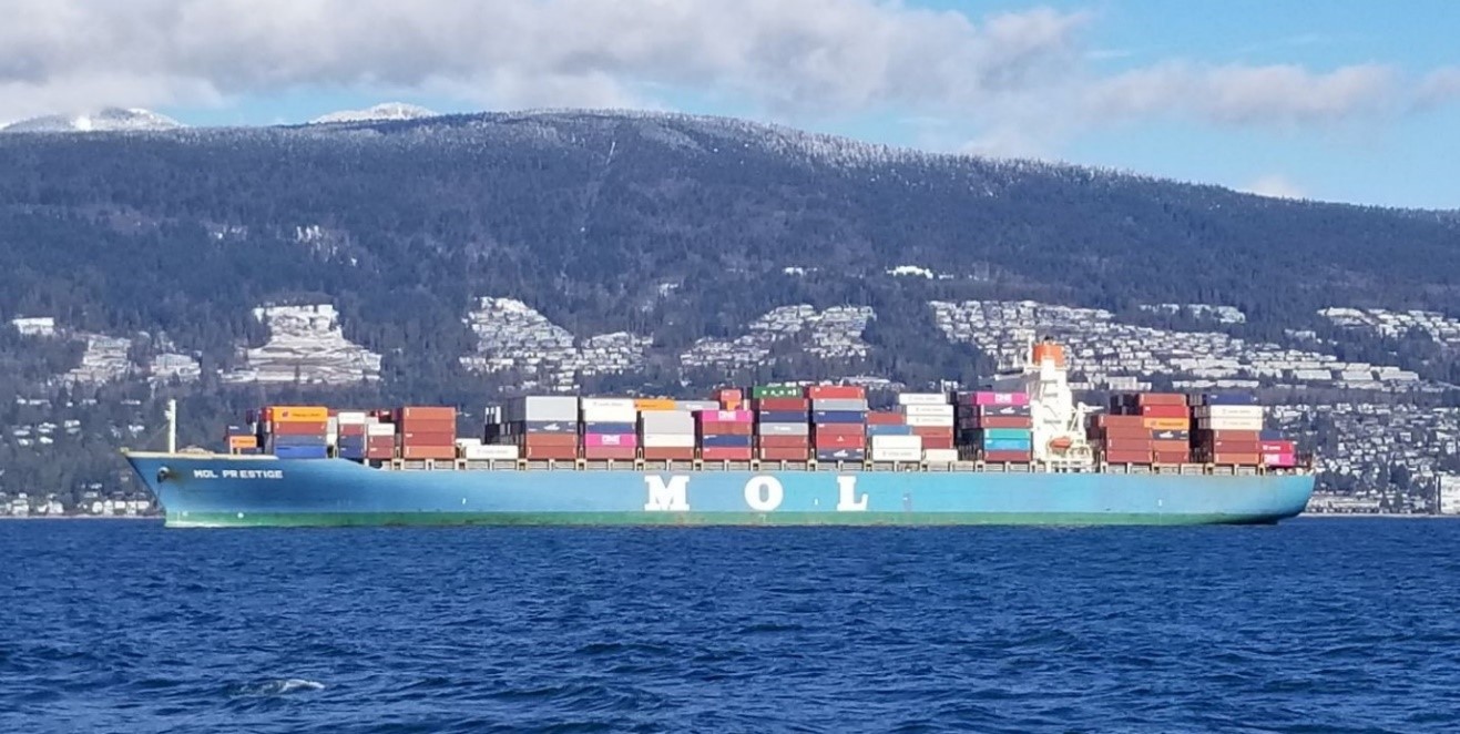
The MOL Prestige is a fully cellular steel-hulled container vessel (Figure 1). The vessel has a container capacity of 6350 twenty-foot equivalent unitsFootnote 1 and is equipped to carry containers above and below the upper deck. The vessel’s cargo space below the upper deck is divided into 8 holds: 7 forward and 1 aft of the engine room.
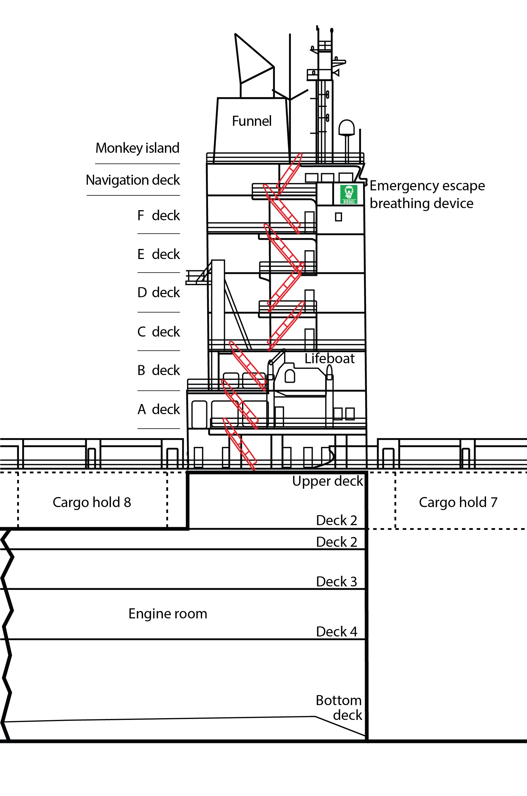
The superstructure consists of the wheelhouse, located on the navigation deck, as well as 7 deck levels below the navigation bridge (the upper deck of the vessel and decks A to F of the superstructure) (Figure 2). The wheelhouse is equipped with all required navigational equipment according to the International Convention for the Safety of Life at Sea (SOLAS).Footnote 2
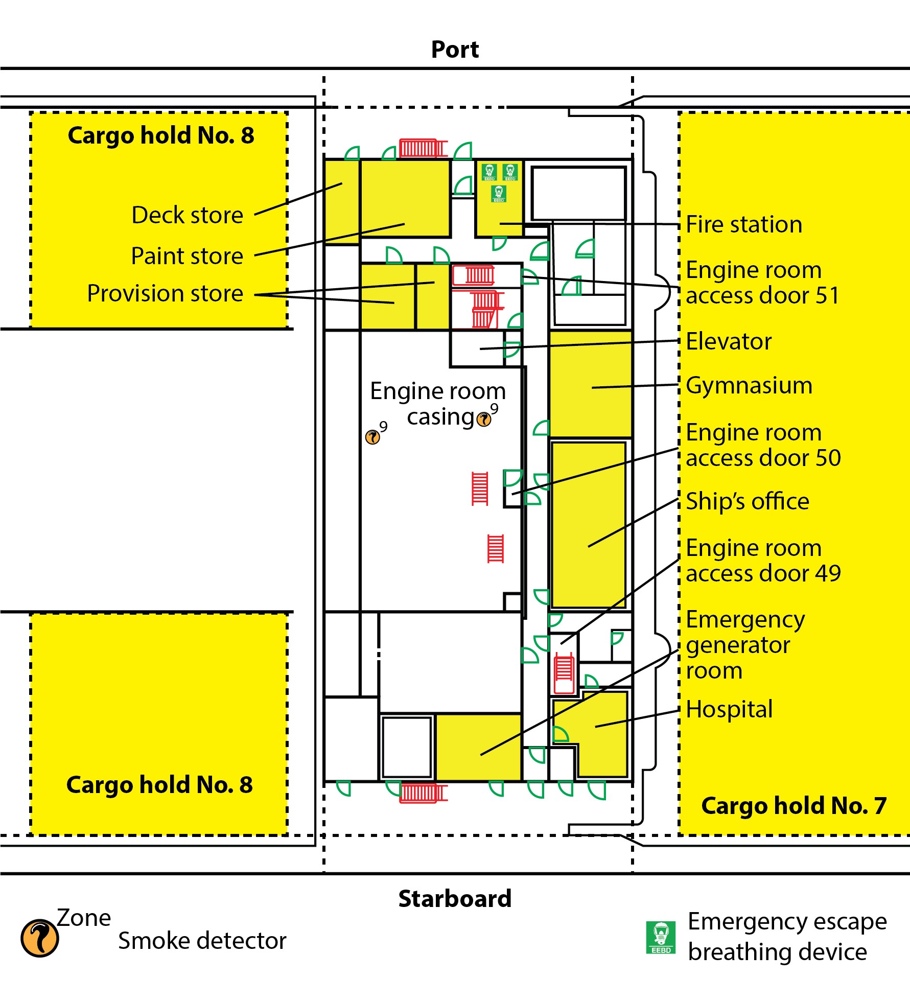
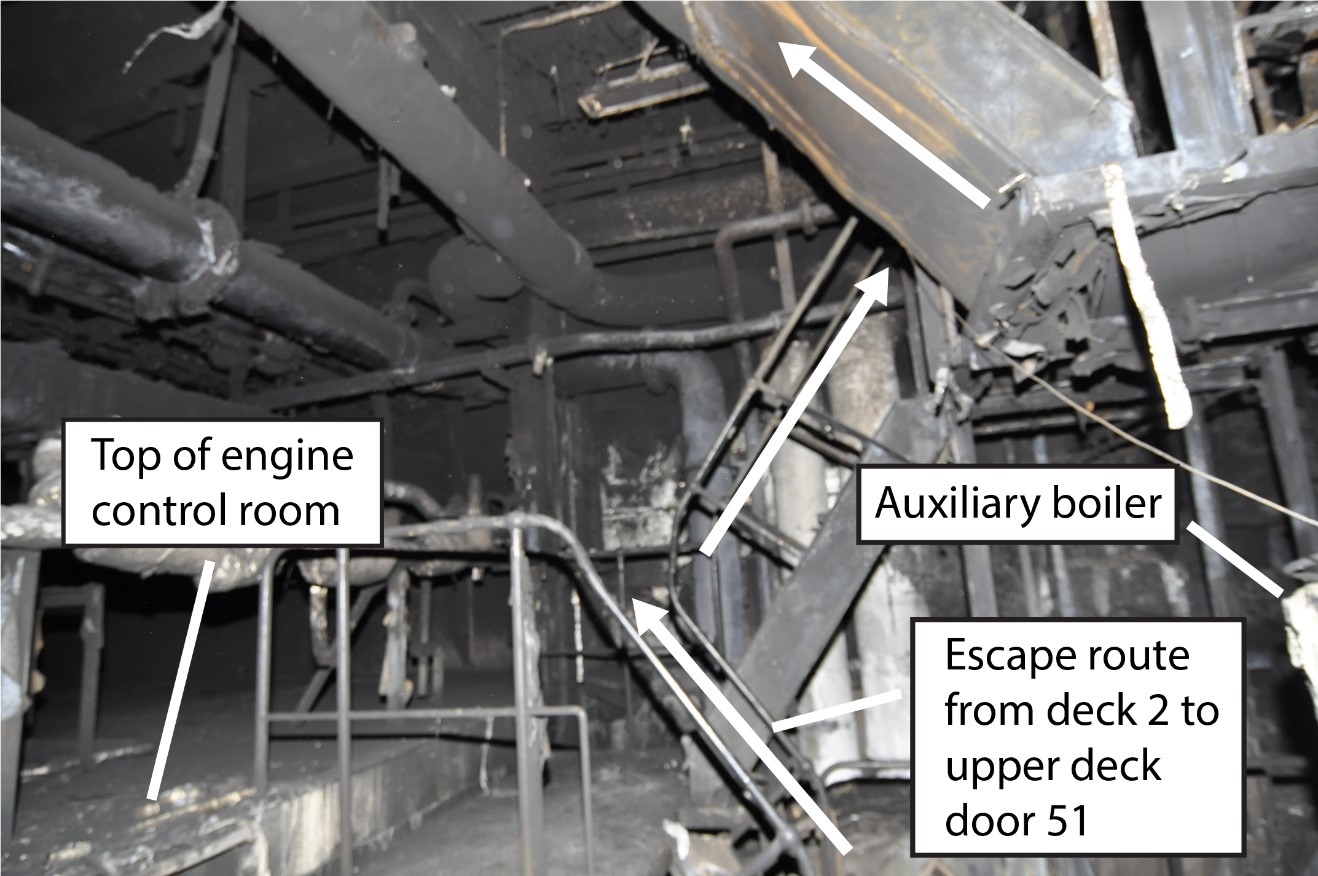
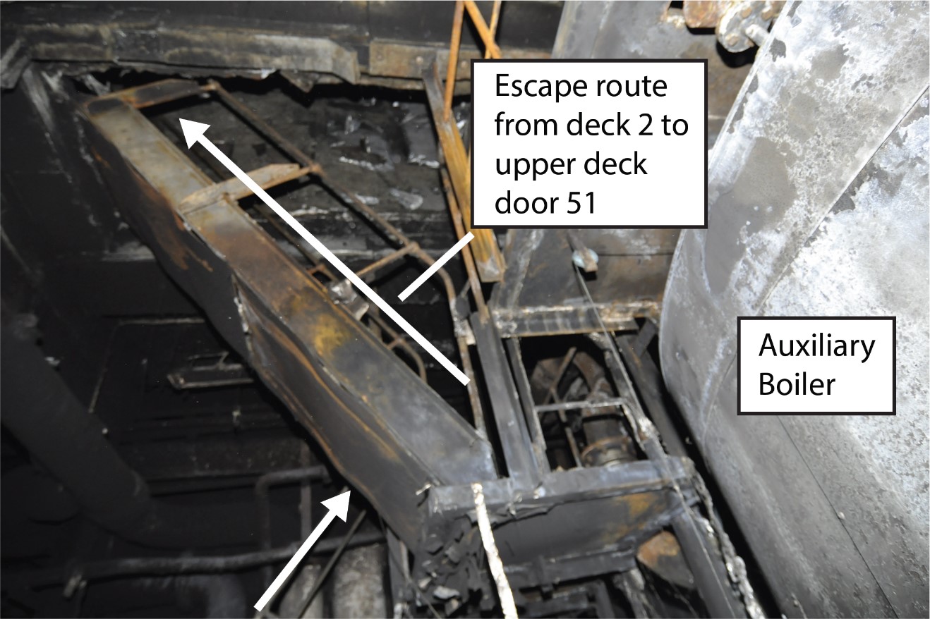
The upper deck accommodation contains the ship’s office, the fire station, the hospital, the emergency generator, and 3 doors (doors 49, 50, and 51) inside the superstructure that open onto stairs leading down to the engine room (Figure 3).
Below the upper deck is the engine room, which is designated as a periodically unattended machinery space.Footnote 3 The engine room contains the main propulsion engine, 4 generator engines, an auxiliary boiler, and an exhaust gas economizer. It also contains other equipment and systems, including the steam heating system and the fuel transfer, supply, and purification systems.
The engine room casingFootnote 4 is contained within the superstructure and is an A-60 class division.Footnote 5 This casing terminates in the funnel, which contains vents with flaps to dispel heat and smoke generated in the engine room. The exhaust pipes from the main engine, the generator engines, and the auxiliary boiler also terminate in the funnel. There is a door leading from the funnel to the monkey island, which is the deck located directly above the navigation bridge (Figure 2).
The engine room spans 4 decks (from highest to lowest, decks 2, 3, and 4 and the bottom deck). An elevator runs between deck 3 in the engine room and the navigation bridge deck, with stops at every deck. The elevator’s default deck can be set as the navigation bridge deck, the upper deck, or deck 2. After a certain period of inactivity on other decks, the elevator returns to the default deck and remains there until called. At the time of the occurrence, the elevator’s default deck was the upper deck. On the navigation bridge deck, the elevator is located in a corner that is not easily visible from the bridge command and control areas. The elevator is powered by the vessel’s emergency generator; the equipment powered by the emergency generator is indicated on a list posted on the bridge.
Deck 2 is divided into 2 levels. The engine control room (ECR) is located on the lower of the 2 levels, on the port side (Figure 4). It is a self-contained room with 3 doors, each with a small window. One of the doors is located closer to the port side of the vessel, and the other 2 are located closer to amidships, with one being adjacent to the elevator. The ECR bulkhead has a large starboard-facing window that provides an athwartship view of the starboard portion of the engine room only (Figure 4). The ECR contains the controls, monitoring systems, and alarms for engine room machinery and is equipped with 2 telephones, one of which is battery-operated and the other of which relies on the vessel’s power. The ECR bulkheads and doors are B-0 class divisionsFootnote 6 and are not smokeproof.
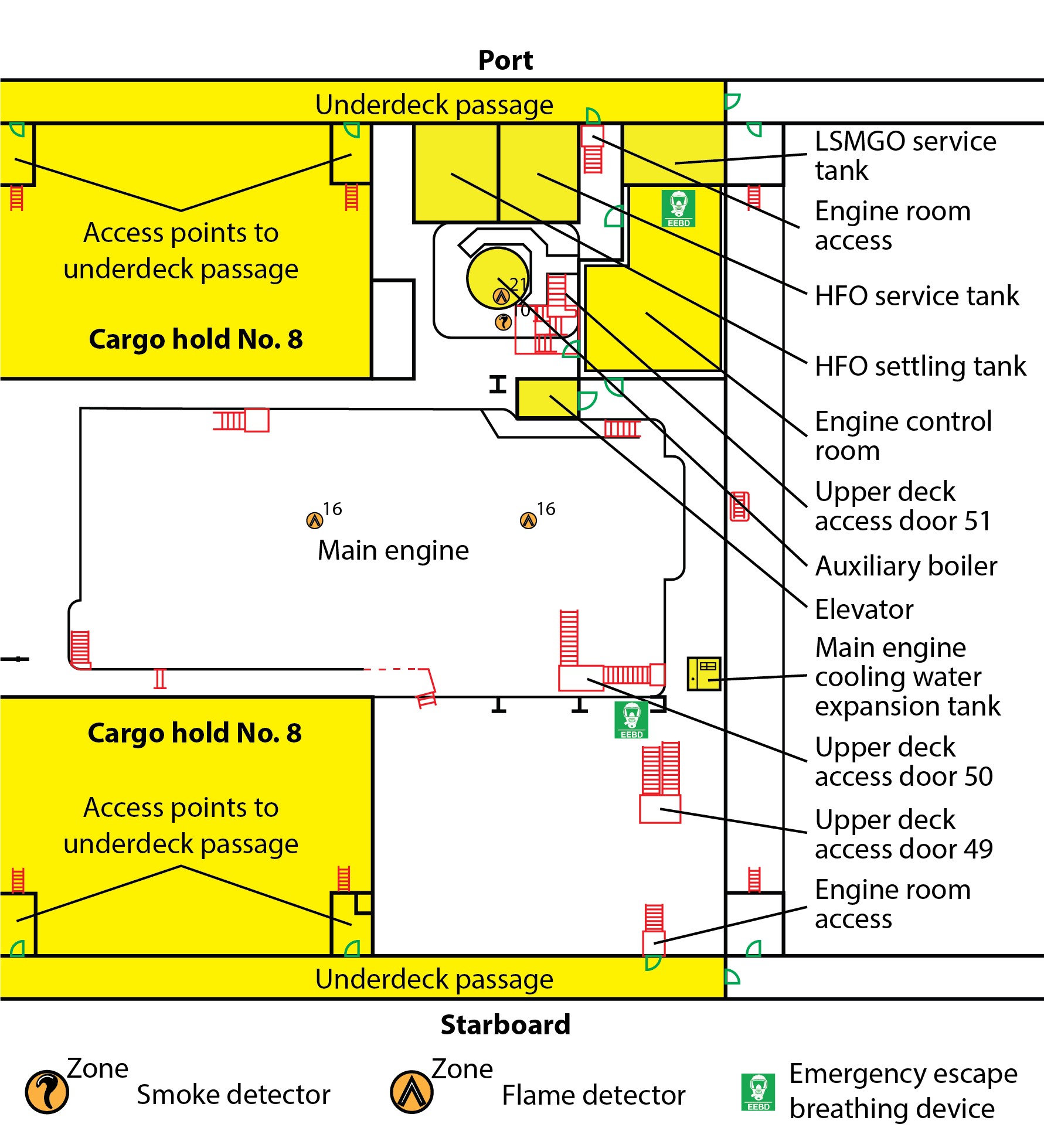
The auxiliary boiler and the heavy fuel oil (HFO)Footnote 7 settling tank and service tank are on deck 3 but extend upwards through deck 2. A service tank for the low-sulphur marine gas oil (LSMGO)Footnote 8 is on deck 2. The upper deck can be accessed from deck 2 by 3 doors (49, 50, and 51) that lead to stairs to the upper deck. An underdeck passage on the upper level of deck 2, runs along each of the port and starboard sides of the vessel; these passages exit into the steering gear room and the cargo holds. Each of these passages has a door that leads to stairs down to the lower level of deck 2.
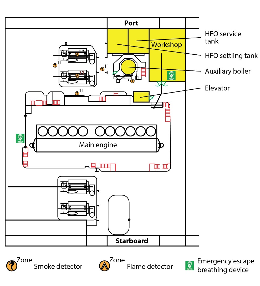
Deck 3 contains the engine room workshop, which is located on the port side near the elevator (Figure 5), as well as the auxiliary boiler and the HFO settling and service tanks, which extend up to deck 2. Deck 3 can be accessed via stairs leading down from deck 2 and leading up from deck 4, as well as via the elevator.
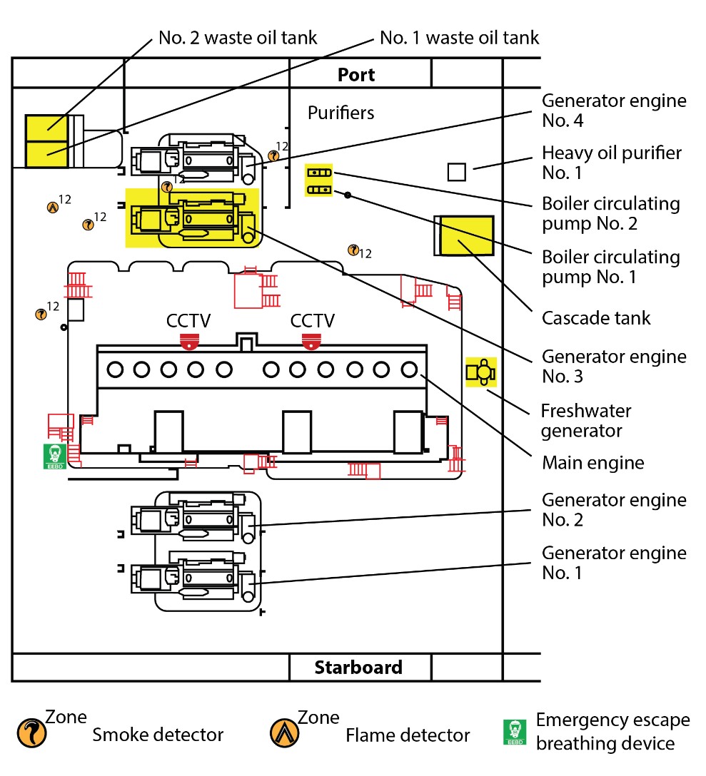
Deck 4 contains all 4 generator engines, 3 HFO purifiers,Footnote 9 1 freshwater generator, 2 boiler circulating pumps, and the cascade tank.Footnote 10 There are 2 closed-circuit television (CCTV) cameras installed on this deck, directed toward the oily-water separator and the bilge overboard valve located on the bottom deck (Figure 6).
Deck 4 can be accessed via stairs leading down from Deck 3 and leading up from the bottom deck (Figure 7).
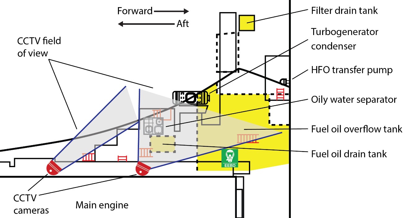
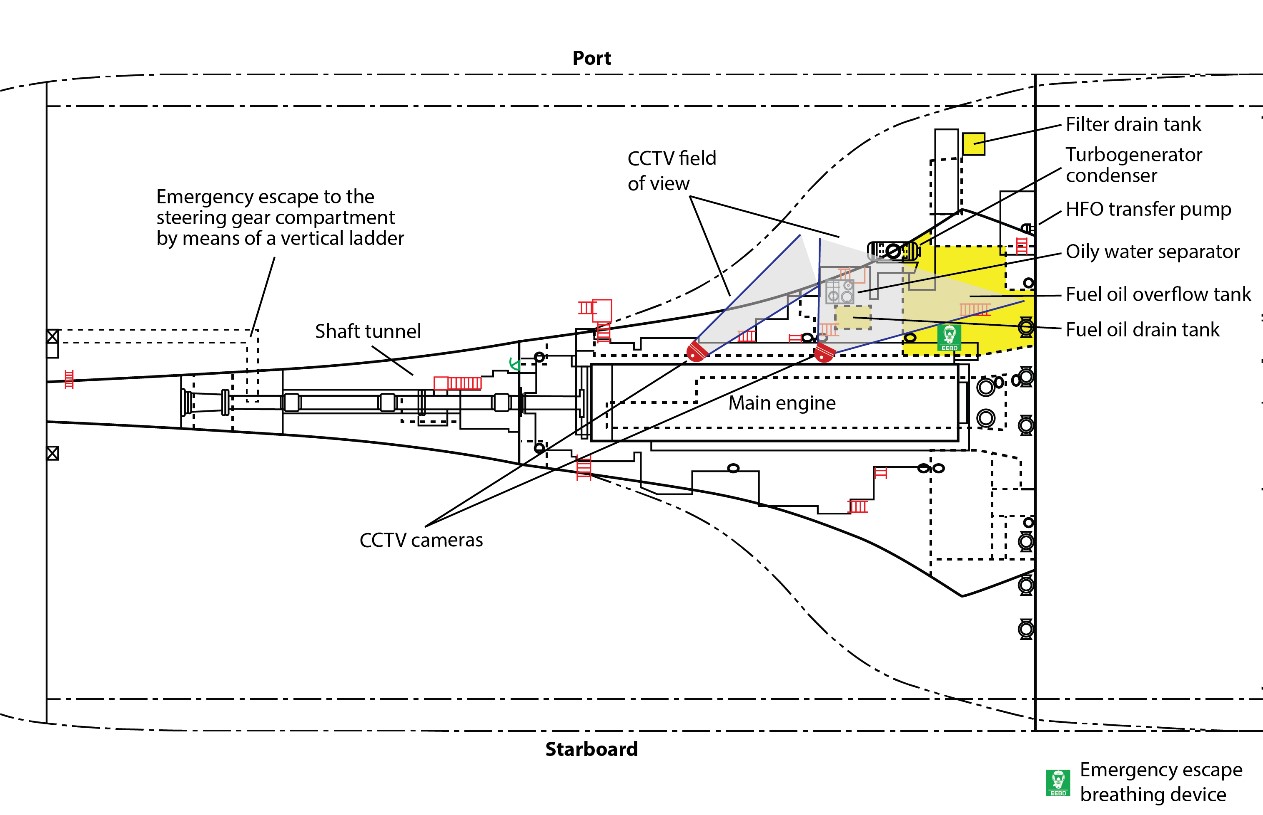
The bottom deck contains the waste oil tanks, drain tanks, fuel oil overflow tank, oily water separator, and fuel oil transfer pumps (Figure 8). The bottom deck can be accessed via stairs leading down from deck 4. An emergency escape leads from the bottom deck through the shaft tunnel to the steering gear room.
1.3 History of the voyage
On 20 January 2018, at 0942 Pacific Standard Time,Footnote 11 the MOL Prestige entered the North American Emission Control AreaFootnote 12 while en route from China to Tacoma, Washington, U.S. Before entering the Emission Control Area, the vessel changed over the main engine and the generator engines from HFO (IFO 500)Footnote 13 to LSMGO in order to comply with Emission Control Area requirements. On 22 January, the vessel arrived in Tacoma for cargo operations. While in port, the vessel took on HFO (IFO 500) and freshwater.Footnote 14
On 24 January at 0700, the MOL Prestige departed Tacoma bound for the Deltaport terminal in Delta, BC. The vessel arrived at the Constance Bank anchorage off Victoria, BC, where it anchored for approximately 3 days before berthing at the Deltaport terminal on 27 January at 0045.
On 29 January, at 2205, the MOL Prestige departed the Deltaport terminal and anchored again at the Constance Bank anchorage. On 30 January, at 1240, the vessel left the anchorage bound for Japan with approximately 5569.4 m3 of HFO, 322.2 m3 of LSMGO, and 235 m3 of freshwater on board. Soon after departure, the freshwater generator began malfunctioning. The chief engineer ordered the engine room crew to stop the generator for the night.
On January 31, at approximately 0600, the engine room crew held a toolbox meetingFootnote 15 in the ECR before starting work. At this time, the engine room crew consisted of the second engineer, the third engineer, the fourth engineer, the junior engineer, and motorman 1.Footnote 16 Soon after the meeting, they began working on the freshwater generator and determined that the condenser tubes in the generator were leaking. At that time, the main engine was running on LSMGO at 78 rpm. The exhaust gas economizer was in operation and was producing steam at a pressure of approximately 7 barFootnote 17 and a temperature of approximately 170 °C.Footnote 18 The auxiliary boiler was not in operation.
At 1700, the chief officer took over the bridge watch from the second officer. The chief officer and chief engineer discussed the issues with the freshwater generator and its impact on the vessel’s water supply. They also discussed preparations for exiting the Emission Control Area, among other things.
At 1940, the master gave the engineers 3 hours’ notice to change over the fuel for the main engine and diesel generators from LSMGO to HFO, as the vessel was exiting the Emission Control Area (Appendix A). At 2015, the chief engineer went to the engine room and instructed the fourth engineer to start one of the HFO purifiers to begin the changeover. The chief engineer then went back to his cabin. At 2030, the third engineer left the engine room and went to his cabin. The remaining engine room crew continued working on the freshwater generator.
1.3.1 Events leading to the fire
At 2045, the fourth engineer, after consulting with the second engineer, started the No. 1 HFO purifier. At 2055, the fourth engineer began transferring HFO from the settling tank to the service tank via the purifier. At 2058, a high-temperature alarm for the purifier sounded. The purifier oil inlet indicated a temperature of 115 °C and rising. In addition, steam and oil fumes were coming from the purifier’s operating water hopper.Footnote 19
Soon after, the fourth engineer went to the settling tank on deck 3 and checked the temperature on the local gauge. It indicated a temperature of 120 °C. The fourth engineer then went to the ECR on deck 2, where a high-temperature alarm for the purifier inlet had activated on the engine room alarm panel.
At 2100, the third officer took over the bridge watch from the chief officer, who went to the upper deck and to the ship’s office to catch up on paperwork. The master was working in the radio room on the bridge.
Meanwhile, motorman 2 arrived in the ECR via the elevator to relieve motorman 1 and to begin his watch at 2100. The light for the high-temperature alarm for the No. 1 purifier inlet was illuminated on the ECR alarm panel. The fourth engineer, who had acknowledged the alarm, was also in the ECR.
The fourth engineer then went down to deck 4 to the freshwater generator and informed the second engineer of the high temperature on the settling tank; the second and the fourth engineers discussed ways to mitigate the high temperature. The second engineer then instructed the fourth engineer to go to the bottom deck to start the HFO transfer pump in manual mode, if possible,Footnote 20 and transfer fuel from bunker tank 7S to the settling tank.Footnote 21
Meanwhile, motorman 2 continued his watch rounds, topped up the main engine jacket cooling water expansion tank on deck 2, and proceeded to the freshwater generator area to assist the second engineer. The second engineer requested that motorman 1, who was at the end of his shift, remain on duty to assist with the repairs.
At approximately 2110, the fourth engineer opened the relevant valves to transfer fuel and started the HFO transfer pump in manual mode. After starting the pump, the fourth engineer returned to deck 4 and went to the purifier. By this time, the quantity of steam and oil fumes coming from the purifier’s operating water hopper had increased. The fourth engineer called the second engineer, who went to the purifier area. The hopper for the No. 3 purifier, which was not in operation, was now also emitting the same fumes.Footnote 22 The second engineer instructed the junior engineer to check the sludge tank’s steam valves, located on the bottom deck, to see whether they were closed.Footnote 23 The junior engineer inadvertently shut off the boiler circulating pump located on deck 4. Meanwhile, the engine room started filling up with white fumes.
1.3.2 Initial fire detection and response
Just before 2115, white fumes were observed coming from the top of the auxiliary boiler near the settling tank. Motorman 2 started up the stairs to deck 2, to the area where the fumes were present, when the fire alarm sounded. As motorman 2 passed the ECR, he went in and acknowledged the fire alarm on the alarm panel to stop the audible alarm. It was then observed that the fumes were increasing and were being sucked into the main engine turbocharger, which could be a fire hazard. Motorman 2 went down to deck 4 to the purifier area and informed the second engineer. The second engineer then rushed to the ECR and acknowledged the fire alarm, which had started sounding again. The second engineer tried to contact the chief engineer in his cabin by telephone, but was unable to do so.
At the same time, the third officer acknowledged fire alarms for multiple zones in the engine room that had activated in quick succession on the fire-detection panel on the bridge. He informed the master, who was still in the radio room, of the initial fire alarm and also called the ECR.
The master called the chief officer, who was in the ship’s office, and the chief engineer, who was in his cabin, and informed them that fire alarms on deck 2 (zone 10) and deck 3 (zone 11) had activated. He asked them to check into it. The chief engineer then went to the elevator to go to the engine room. The chief officer exited the ship’s office, went across the hallway, and opened door 50, at which time fumes were present in the engine room. He informed the master that the engine room was smoky and asked the master to sound the general alarm. The chief officer then went to the fire station. The master contacted the managing company, Bernhard Schulte Shipmanagement (China) Company Ltd. (BSM China) and informed them of the situation,Footnote 24 but did not activate the general alarm.
Meanwhile, in response to the increased steam and oil fumes from the purifiers as well as the fumes in the engine room, the fourth engineer went to the bottom deck and stopped the HFO transfer pump at approximately 2116, and then went to the fourth deck and stopped the purifier.
Soon after, the remaining engine room crew (the fourth engineer, the junior engineer, motorman 1, and motorman 2) went to the ECR. On the way, fumes were observed behind the elevator shaft and white fumes were observed above generator engines 3 and 4.
At approximately 2117, the general fire alarm activated automatically, sounding across the vessel.Footnote 25 At this time, the chief engineer was in the elevator on the way to the engine room. The third engineer, who was in his cabin, called the bridge after the general fire alarm sounded. The master told the third engineer that there was a fire in the engine room.
After the general fire alarm sounded, the wiperFootnote 26 immediately came to the fire station and was the first crew member to arrive. The chief officer ordered the wiper to don the firefighting outfit located at the fire station and enter the engine room, but the wiper refused.Footnote 27 The chief officer then ordered one of the 2 able seamen who had arrived at the fire station to don the firefighting outfit, including the self-contained breathing apparatus (SCBA). The chief officer ordered the other able seaman to bring another firefighting outfit from a locker on deck D.
Meanwhile, once the remaining crew had entered the ECR, the chief engineer arrived in the engine room via the elevator and entered the ECR through the starboard door nearest to the elevator. When he entered the engine room, no smoke or fumes were observed. The elevator then returned to the upper deck. Once in the ECR, the chief engineer looked out the starboard-facing window in the ECR bulkhead and noted that the visibility on the starboard side of the engine room was good. The chief engineer and the engine room crew in the ECR then discussed the fire alarm and the origin of the white fumes.
The second engineer ordered motorman 1 to check the decks below. At 2118:06, the CCTV captured footage of oil spraying onto the oily bilge water separator located on the bottom deck. Motorman 1 exited the ECR and was partly down the stairs from deck 2 to deck 3 when smoke and flames were observed on deck 3 near the auxiliary boiler area. He returned to the ECR and informed the second engineer. The junior engineer informed the second engineer that he had inadvertently turned off the boiler circulating pump on deck 4. The junior engineer then exited the ECR through the starboard-side door and restarted the pump at 2118:34. At 2118:39, burning oil and flames were observed near the stairs between deck 3 and 4, close to the No. 3 generator.Footnote 28 Soon after, the engine room started rapidly filling with black smoke. At 2119:05, the junior engineer rushed back into the ECR. At this time, the generator frequency also began fluctuating.
Meanwhile, the third engineer had reached the upper deck from deck C using the stairs. He proceeded to door 51 and opened it, at which time smoke was visible in the engine room. The third engineer then contacted the second engineer, who was in the ECR, using a hand-held transceiver and determined how many crew were in the ECR.
At approximately 2122, the CCTV captured footage of a flash, after which time the CCTV footage was almost entirely obscured as the engine room filled with black smoke. The chief engineer called up to the bridge, informed the master of the smoke, and asked the master to reduce the speed of the main engine and hand over the engine controls to the engine room. The chief engineer and second engineer then stopped the main engine and other machinery, except for generator engines No. 1 and No. 3, which were running in parallel.
Soon after, the circuit breaker for generator engine No. 3 tripped and generator engine No. 4, which was on automatic, started and came online. The engineers then manually stopped generator engine No. 3 from the ECR. Through the window in the ECR port-side door, black fuel was observed flowing down the sides of the settling tank onto the platforms and decks below.
At the fire station, not all of the crew had mustered in response to the general fire alarm. The chief officer asked the master to announce the fire on the public address system, which the master did.
By 2120, all the remaining crew had mustered at their designated muster stations. Meanwhile, the master changed the vessel’s automatic identification system setting to “not under command” (NUC)Footnote 29 and switched on the NUC lights.
At 2122, the chief engineer contacted the master from the engine room by telephone and asked the master to instruct the third engineer and the electro-technical officer to shut the quick closing valvesFootnote 30 for all oil tanks in the engine room. He also requested activation of the emergency stopsFootnote 31 from the fire station. Soon after, the third engineer activated all the quick closing valves, closed the funnel flapsFootnote 32 (except one that was hot to the touch), and closed the engine room ventilation dampers.Footnote 33 The electro-technical officer helped the third engineer activate the emergency stops.
At 2125:27, the second engineer stopped generator engine No. 1 manually from the ECR, and the circuit breaker for generator engine No. 4 tripped. At this time, the vessel lost all electrical power and the CCTV footage ended. Shortly afterward, the emergency generatorFootnote 34 started automatically and came online.
At 2134, the emergency generator shut down and the vessel lost electrical power, leaving the crew without lighting or power. The electro-technical officer restarted the emergency generator shortly afterward.
1.3.3 Egress and evacuation from the engine room
At approximately 2126, the 6 crew in the ECR attempted to exit the ECR using the starboard-side door and reach the starboard-side exits to the upper deck; however, they were unable to do so because thick smoke had built up in the engine room. The elevator was considered as an egress option but the crew decided against itFootnote 35 and returned to the ECR. The fourth engineer checked the port-side door of the ECR with a temperature gun and obtained a reading of 90 °C. The chief engineer called the bridge using the hand-held transceiver and asked the bridge crew to send down emergency escape breathing devices (EEBDs).Footnote 36
The chief officer ordered the wiper to get the 2 EEBDs located at the fire station and ordered the able seaman, who was now attired in the firefighting outfit, to take the EEBDs down to the ECR. The able seaman took the 2 EEBDs, opened door 51, and started down the stairs, but encountered thick smoke. He could not reach the engine room because of the smoke and returned to the upper deck. The chief officer then asked other crew at the muster station to enter the engine room, but they all refused. Meanwhile, the third engineer started the emergency fire pump from the fire station. The chief officer ordered the third engineer and the electro-technical officer to go to the pump and verify that it was running satisfactorily and building the required pressure.
The chief officer then donned the SCBA that the able seaman had been wearing, without the protective clothing from the firefighting outfit, and entered the engine room via door 51. The chief officer had the 2 EEBDs with him and a lifelineFootnote 37 attached to him. He was wearing coveralls, and his hands were bare. As the chief officer made his way down the stairs into the engine room, he held the railing with one hand and the EEBDs in the other. Liquid was dripping down from the tanks and splashing onto the stairs and platforms (around the boiler top level) and onto the decks below, making deck 2 slippery as the chief officer proceeded. At this time, the master made a distress call on very high frequency (VHF) radiotelephone channel 16Footnote 38 to request assistance from other vessels in the vicinity.
At 2130, upon entering the ECR, the chief officer handed the 2 EEBDs to the chief engineer. The chief engineer then also took charge of the EEBD that was located in the ECR. The chief officer’s boots were soaked in oil. The chief officer demonstrated to the chief engineer, second engineer, and fourth engineer how to properly don the EEBDs. The chief officer also explained that he had encountered thick black smoke and dripping oil, but no heat, on his way to the ECR.
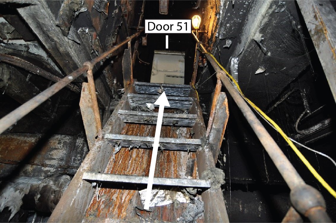
At 2138, 3 of the 6 crew in the ECR donned the EEBDs and followed the chief officer out of the engine room using the lifeline attached to the chief officer. As the 4 crew members made their way up the stairs (figures 9, 10, and 11), they encountered dense smoke and heat from the fire. The chief officer tripped while making his way up the stairs and grasped the railings to regain his balance, burning the palms of his hands. The chief engineer also tripped on the stairs and burned his arms upon making contact with the railings. The second engineer similarly sustained burns to his palms and forearms. The fourth engineer slipped and hit his head, which dislodged his EEBD and caused burns to his ears.
Shortly after exiting the engine room, the 4 crew members were treated for burns in the ship’s hospital, located on the upper deck. After receiving treatment for his burns, the chief engineer went up to the bridge and updated the master about the 3 crew members who were still trapped in the ECR. At this time, because of his burns, the chief engineer delegated some of his responsibilities to the second engineer, including the authority to activate the carbon dioxide (CO2) fixed fire suppression system.
The remaining crew in the ECR were in constant communication with the master by ship’s telephone and hand-held transceiver. They reported smoke and heat in the ECR and difficulty breathing. They made repeated requests for evacuation. They found a bottle with water in it and used it to wet rags, which they then used to cover their faces to try to protect themselves from the smoke and heat. The junior engineer tested the door temperatures and obtained a reading of 85 °C on the port side and 50 °C on the starboard side. Meanwhile, the master had identified that the elevator was not operational and was stuck on the upper deck level. The electro-technical officer was assigned to work on it, but he was unable to make it functional and was assigned firefighting duties.
The master asked for a volunteer to enter the engine room to rescue the trapped crew, but there were none. The master then called the company for further instructions. The master asked the trapped crew to try to escape without assistance from the crew outside the engine room. The remaining crew made repeated attempts to escape, but these were unsuccessful, and the air in the engine room was now toxic. Smoke was also getting through the closed door into the ECR, and the temperature was rising.
1.3.4 Firefighting
By 2140, the crew had started boundary cooling behind the superstructure, because a fire had been discovered on the upper deck, in the gap between cargo holds 8P and 8S in the vicinity of the settling and service tanks in the engine room. The crew members extinguished this fire, and the chief officer then ordered the crew to place 2 hoses inside the aft engine room blower casings to direct water inside the engine room. The crew also continued boundary cooling in the paint store and the adjacent deck store, as well as the dry provision store,Footnote 39 where smoke had been observed. The water directed into the dry provision store turned to steam instantly. More hoses were rigged on deck B to cool the engine room casing from the outside. One hose was rigged on the upper deck, and the crew directed water onto door 51 to determine whether the door was hot. The water directed onto the door did not turn to steam, so the crew partially opened the door and directed water toward the areas containing the boiler and the settling tank.
The chief officer informed the master that the fire and smoke were increasing rapidly. The water used for boundary cooling was turning to steam and the temperature around these areas being boundary cooled was increasing. The master then discussed with the chief engineer whether it was possible to release CO2 into the engine room without affecting the ECR. The chief engineer called the second engineer on the hand-held transceiver and checked with the second engineer and the chief officer at the fire station. They expressed concerns about the safety of the crew in the ECR. The trapped engine room crew heard the discussion over the hand-held transceiver, which caused panic. Motorman 1 attempted to escape but sustained smoke inhalation and serious burns to his hands. He returned to the ECR.
The master also discussed the possibility of releasing CO2 into the engine room, which included the ECR, with BSM China. BSM China advised the master to try every other possibility first.
At 2225, fire alarms for zones 1, 3, 4, 5, and 6 sounded.Footnote 40 Soon after, the elevator became functional and opened on the bridge.Footnote 41 The master notified BSM China that it was a potential egress option and BSM China requested that he look into the possibility of using it. The master notified the trapped crew that he would send the elevator down to them. At 2240, 1 hour and 26 minutes after the fire started, the junior engineer, motorman 1, and motorman 2 covered their faces with wet cloths and exited the engine room using the elevator. They took the elevator to deck C and walked up the stairs to the bridge.
Once the trapped crew had escaped from the engine room, the crew removed the hoses from inside the engine room blowers and closed the dampers and the last flap in the funnel, at times directing water on the flap to cool it. The master ordered the CO2 to be discharged into the engine room.
At 2250, the second engineer released CO2 into the engine room from the fire station. Soon after, the paint on the outside of door 51 started blistering and smoke began coming out from around the door frame. The crew cooled the door down with water. They also hosed down the dry provision store, which was showing signs of heating up. The crew took a hose from inside the steering gear compartment and cooled the engine room bulkhead near cargo hold No. 8 from inside the port underdeck passage. The crew flooded the underdeck passage with water, which entered the steering gear roomFootnote 42 and damaged the emergency steering electrical controls.
The chief officer, while on his way to the ship’s hospital on the upper deck, passed by the gymnasium. Popping sounds were audible in the gymnasium, suggesting the presence of heat or fire. He then directed the crew to begin cooling the engine room bulkhead from inside cargo hold No. 7.
In consultation with the master, the third engineer entered the CO2 roomFootnote 43 and manually released 30 cylinders of CO2 into the engine room. A leaking sound could be heard from outside the CO2 room. The electro-technical officer, who was standing outside the CO2 room, cautioned the third engineer that CO2 was being released inside the CO2 room and directed him to come out. Later, the third engineer donned an SCBA, entered the CO2 room, and manually released another 54 cylinders.
On 01 February at 0209, the master informed Canadian Coast Guard Marine Communications and Traffic Services (MCTS) that the vessel’s supply of CO2 was low and that smoke was still coming out of the funnel. He also indicated that boundary cooling in the No. 7 cargo hold, the No. 8 cargo hold, and the accommodation was continuing.
At 0400, boundary cooling was stopped momentarily to help the crew assess the situation. The fire appeared to be under control. The crew checked the temperature in the underdeck passage adjacent to the engine room door and noted that it had decreased. The chief officer reported this to the master.
At 1650, the second engineer and motorman 2, wearing SCBAs, entered a few steps into the engine room to obtain the status of the fire, which was still smouldering. They rigged a hose from door 51 on the upper deck and pointed it toward the settling and service tanks.
Between 1700 and 1715, the second engineer and the electro-technical officer, wearing SCBAs, entered the engine room to ascertain the status of the fire. They reported that the air on deck 3 was breathable and that there was no sign of fire smouldering.
At 1800, the third engineer and motorman 2, wearing SCBAs, entered the engine room. They walked around deck 2 and 3 and noted that the fire had been extinguished.
1.3.5 Search and rescue response
On 31 January at 2137, the master used the vessel’s Inmarsat-C to send an undesignated distress message.Footnote 44 The message was received by the U.S. Coast Guard (USCG), who contacted the Joint Rescue Coordination Centre (JRCC) in Victoria at 2223. The message from the USCG provided position information for the MOL Prestige and stated that the vessel had an engine room fire and that 3 crew members were trapped in the engine room. Soon after, JRCC tasked the Canadian Coast Guard ship (CCGS) Sir Wilfrid Laurier to assist. JRCC also tasked the Royal Canadian Air Force (RCAF) search-and-rescue aircraft 465 (R465) based in Comox, BC.
Meanwhile, at 2243, the oil tanker Eagle Bay, which was 120 nm northwest of the MOL Prestige, heard the distress call and contacted JRCC. JRCC told the Eagle Bay to proceed to the MOL Prestige.
At 2244, JRCC conveyed the message to MCTS in Prince Rupert, BC. JRCC also informed MCTS that CCGS Sir Wilfrid Laurier had been tasked. JRCC instructed MCTS to send out a Mayday relay, which MCTS did.
At 2247, the oil tanker Polar Resolution, which was 75 nm east of the MOL Prestige, responded to the Mayday relay and was tasked by JRCC to assist.
Between 2255 and 2319, R465 and CCGS Sir Wilfrid Laurier began their operation.
By 2342, the master had made direct contact with MCTS and informed them that all crew were accounted for, that the engine room had been flooded with CO2, and that the fire had been extinguished. The master requested medical assistance and indicated that they were going to investigate the fire. The master also told MCTS that the vessel was powered only by the emergency generator.
At 0001 on 01 February, a SafetyNETFootnote 45 was released. Soon afterward, MCTS informed the master of the MOL Prestige that the Polar Resolution was 40 nm west of the MOL Prestige.
At 0120, the MOL Prestige informed MCTS that the fire was still burning and was not under control, and that the master was reassessing the situation.
At 0137, the master stated that they were in contact with Polar Resolution, which was 2 hours away. The master also stated that he was releasing the CO2 manually. He indicated that the lifeboatFootnote 46 was being prepared in order to abandon the vessel.
At 0317, the master informed MCTS that the engine room fire was still burning and that they were unable to access the engine room. The underdeck passages could be entered. The master stated that the smoke was still the same and that the vessel had 6 hours of fuel left to operate the emergency generator. The master also informed MCTS that the fire pumps were connected to the emergency generator.
At 0356, the Polar Resolution reached the MOL Prestige and stood by to assist. The crew on the MOL Prestige continued with boundary cooling. At 0800, the master informed MCTS that there was less smoke coming from the funnel.
At 0907, MCTS contacted the Transportation Safety Board of Canada (TSB) and reported that there was a fire on the MOL Prestige.
At 0942, the master informed MCTS that the crew were using buckets to transfer LSMGO to the emergency generator from the LSMGO service tank. At 1044, the master informed MCTS that boundary cooling was ongoing, that smoke was still coming out of the funnel, and that approximately 60 CO2 cylinders were left.
At 1134, the Eagle Bay reached the MOL Prestige and was instructed by JRCC to remain on site until directed. At 1135, the Polar Resolution informed MCTS that it was in communication with the MOL Prestige. The Polar Resolution also stated that its lifeboats were ready in case the crew on the MOL Prestige had to abandon the vessel. Soon after, the Eagle Bay was told it could stand down.
At 1414, the U.S.-registered tug Denise Foss, which had been contracted to tow the MOL Prestige, left Neah Bay, Washington, U.S.
At 1513, R465 and another helicopter, RCAF search and rescue helicopter 903, evacuated the chief officer and motorman 1 to hospital in the Village of Queen Charlotte, BC. The chief engineer, second engineer, and motorman 2 were also assessed by the search-and-rescue technicians.
At 2341, CCGS Sir Wilfrid Laurier arrived on scene, and the Polar Resolution was released from standby. On 02 February, at 0800, CCGS Sir Wilfrid Laurier requested boarding arrangements from the MOL Prestige. Soon after, the fast rescue craft from CCGS Sir Wilfrid Laurier came alongside the MOL Prestige. Between 1000 and 1215, the crew of CCGS Sir Wilfrid Laurier provided first aid to the chief engineer, second engineer, and fourth engineer.
The vessel remained adrift until 03 February, with CCGS Sir Wilfrid Laurier standing by, until the tug Denise Foss arrived at 1744 and began towing it to Seattle, Washington, U.S. The crew remained on board, with the exception of the 2 who were evacuated. The tug arrived with the MOL Prestige on 11 February. The vessel was repaired in Seattle and returned to service on 20 March.
1.4 Damage to the vessel
The vessel sustained the following damage as a result of the fire:
- Longitudinal girder no. 18, above the settling tank and the HFO service tank, was deformed between frames 27 and 35.
- The upper deck plate above the settling and HFO service tanks was deformed between frames 27 and 30, as were longitudinal girders no. 18 and 20 on the port side.
- The upper deck, aft of the accommodation between No. 8 cargo hold on the port side and the engine room, was deformed between frames 28 and 33 on the port side.
- There was considerable damage to electrical equipment, including the main switchboard, generator engines No. 3 and No.4, and various power cables.
- The fire detectors in the engine room were burned or otherwise damaged by the heat.
- The A-60 class division insulation between the engine room and the accommodation spaces was damaged by the heat.
- Firefighting equipment—including fire extinguishers, fire hoses, and EEBDs—was damaged.
- The control lines for the fixed fire (CO2) extinguishing system for the cargo holds were damaged by the heat.
1.5 Injuries
Five of the crew members were seriously injured.Footnote 47 Most of the injuries were burns, and one crew member also had smoke inhalation.
1.6 Environmental conditions
At the time of the occurrence, the sky was overcast and the wind varied between southerly, southeasterly, and southwesterly at approximately 11 to 20 knots. There was a 3 m swell. The sea and air temperatures were approximately 6 °C.
At 1134 on 01 February, the wind was southeasterly at 30 to 35 knots, reducing to southwesterly at 25 knots by 1732. The swell was 6 m.
At 0402 on 02 February, the wind was west-southwesterly at 27 knots, and the swell was 2 to 3 m.
1.7 Vessel certification
The MOL Prestige is a SOLAS convention vessel that was crewed, equipped, and certified in accordance with existing regulations. As required by the International Management Code for the Safe Operation of Ships and for Pollution Prevention (the ISM Code), the vessel held a valid safety management certificate.Footnote 48 This certificate had been issued by DNV-GL on 05 June 2017. The vessel was classed with Nippon Kaiji Kyokai (ClassNK),Footnote 49 and had last undergone an annual inspection on 28 June 2017.
1.8 Personnel certification and experience
The crew on the MOL Prestige held certificates in accordance with the provisions of the International Convention on Standards of Training, Certification and Watchkeeping for Seafarers (the STCW Convention).
The master held a Master certificate of competency issued by the government of India and endorsed by the Maritime and Port Authority of Singapore (MPA) that was valid until 19 July 2021. He had been working as a master since 1981, and on container vessels since 1985. He had worked on BSM-managed vessels since 2002. He joined the MOL Prestige on 19 September 2017.
The chief officer held a Master certificate of competency issued by the government of India and endorsed by the MPA that was valid until 29 July 2020. He began his sea career in 2005 and had worked on container vessels since 2006. He had worked in the capacity of chief officer since 2013. He joined BSM in November 2016 and began working as a trainee master on the MOL Prestige on 07 August 2017. At the time of the occurrence, he was on a 2-month extension of his 4-month contract.
The third officer held a Second Mate certificate of competency issued by the government of India and endorsed by the MPA that was valid until 26 July 2021. He began his sea career in 2013 as a deck cadet with BSM. After obtaining his certificate of competency in 2016, he joined another company as a junior deck officer. On 03 January 2018, he rejoined BSM as a third officer.
The chief engineer held a Marine Engineer Officer Class I certificate of competency issued by the government of India and endorsed by the MPA that was valid until 17 October 2020. He began his sea career in 2003 with BSM and had worked as a junior engineer, fourth engineer, third engineer, and second engineer. In 2012, he became a chief engineer and worked in this capacity on 6 other container vessels similar to the MOL Prestige. He joined the MOL Prestige as chief engineer on 23 January 2018 while the vessel was in Tacoma. The chief engineer had received a few hours of familiarization on the day he joined the vessel, which included taking rounds of the vessel with the previous chief engineer and identifying all safety-related items.
The second engineer held a Second Engineer certificate of competency issued by the United Kingdom and endorsed by the MPA that was valid until 17 July 2018. He began his sea career on car carriers in 2005. In 2009, he began working on container vessels, first as a fourth engineer and then as a third engineer. In 2013, he began working as a second engineer with BSM. He joined the MOL Prestige as second engineer on 17 December 2017. After joining the vessel, the second engineer received a total of 18 hours of familiarization.
The third engineer held a Marine Engineer Officer Class II certificate of competency issued by the government of India and endorsed by the MPA that was valid until 08 May 2020. He began his sea career in 2008 and had worked as a junior engineer and fourth engineer on container vessels up to 2013. He started working for BSM in 2013 and joined the MOL Prestige on 26 December 2017. After joining the vessel, the third engineer received a total of 12 hours of familiarization.
The fourth engineer held a Marine Engineer Officer Class IV certificate of competency issued by the government of India and endorsed by the MPA that was valid until 06 September 2021. He began his sea career in 2014 and had sailed on oil tankers for 3.5 months and on container vessels for 6 months as a junior engineer. After obtaining his certificate of competency, he joined BSM as a trainee fourth engineer and joined the MOL Prestige on 17 January 2017 for 1 tour of duty. In August 2017, he joined the MOL Prestige for a second tour of duty as fourth engineer.
The electro-technical officer held an Electro Technical Officer certificate of competency issued by the government of India on 27 March 2017. He began his sea career with the Indian Navy and retired in 1997. He joined BSM in 2011 and the MOL Prestige on 26 December 2017.
The junior engineer had completed a diploma in marine engineering in India. This was his first contract, and he had been on board the MOL Prestige since June 2017.
Motorman 1 began his sea career in 2000 and had sailed on various types of vessels, including container vessels. He joined BSM in 2007 and had sailed on board the MOL Prestige since 26 September 2017.
Motorman 2 began his sea career in 2000 and had sailed on various types of vessels, including container vessels. He joined BSM in 2011 as a motorman on container vessels and had been on board the MOL Prestige since 19 September 2017.
1.9 Fuel types used by the MOL Prestige
The MOL Prestige ran on 2 different types of fuel. Within an Emission Control Area, the vessel would run on low-sulphur marine gas oil (LSMGO); outside an Emission Control Area, it would run on heavy fuel oil (HFO).
HFO, a residual fuel obtained from the distillation of crude oil, is widely used in marine diesel engines and boilers. It normally has a higher viscosity and sulphur content than LSMGO. Because of its higher sulphur content, HFO is prohibited from use in Emission Control Areas.
LSMGO is a pure distillate refined from petroleum products for use in diesel engines, gas turbines, or heating/boiler plants. Because of its low sulphur content, it is suitable for use in Emission Control Area s. LSMGO has a lower viscosity than HFO, which can make it more prone to leaks when used in a system designed for HFO.
The minimum auto-ignition pointsFootnote 50 and boiling points for HFO and LSMGO are typically as follows (Table 2):
| Oil type | HFO | LSMGO |
|---|---|---|
| Auto-ignition point (°C) | Min 250 | Min 250 |
| Boiling point (°C) | Min 175 | Min 154 |
The flashpointFootnote 51 for the HFO in use at the time of the occurrence was greater than 70 °C. The flashpoint for the LSMGO on the vessel at the time of the occurrence was greater than 84 °C. The International Maritime Organization (IMO) regulations require the minimum flashpoint for both HFO and LSMGO used in the machinery spaces to be greater than 60 °C.
Both HFO and LSMGO, when heated above their flashpoints, release flammable vapour, heavier than air, that can ignite when exposed to open flames, sparks, and static discharge. Mists or sprays may be flammable at temperatures below the normal flashpoint. The vapour concentration can be measured in percentage in the air, providing a lower flammability limitFootnote 52 and an upper flammability limit.Footnote 53
The lower flammability limit of HFO can be affected by a wide range of factors, such as
- the flashpoint temperature of the HFO
- the amount of exposed surface area
- whether the HFO has been agitated
- the amount of air in the tank containing the HFO (the headspace)
- the rate at which air is exchanged through the vents in this space
The headspace of any tank containing HFO must be considered hazardous, regardless of the flashpoint. If a tank has minimal headspace and little or no air exchange, the hydrocarbon vapour emitted by a fuel even at a temperature well below its flashpoint can concentrate quickly, reaching or exceeding the lower flammability limit.
1.10 Fuel systems
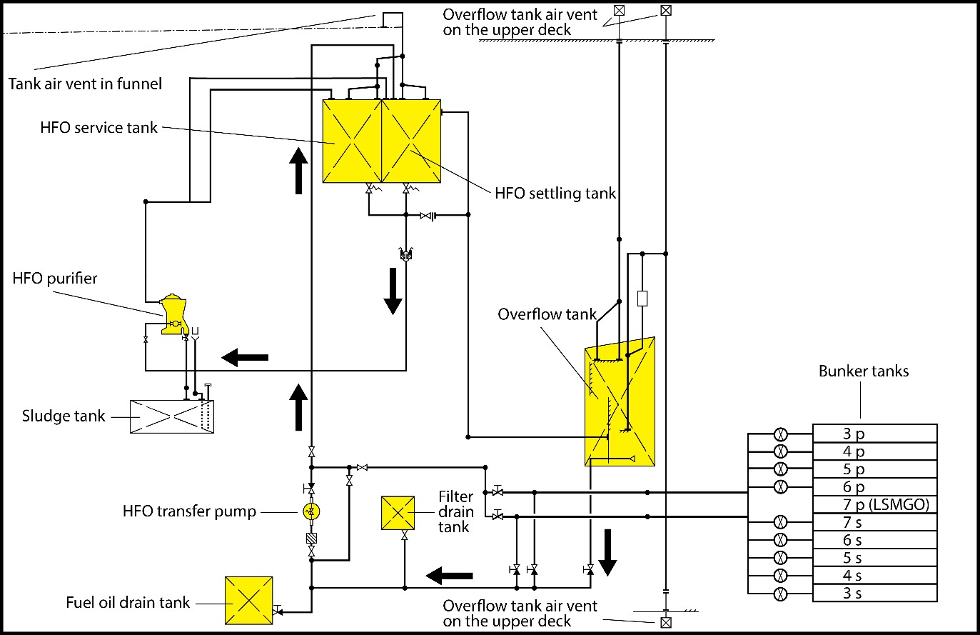
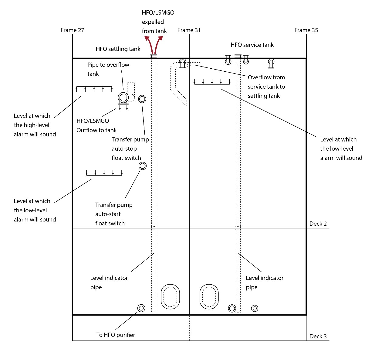
The MOL Prestige had 2 fuel systems: one for HFO and one for LSMGO. The HFO fuel system consisted of bunker tanks, a settling tank, a service tank, 3 purifiers, and a transfer pump (Figure 12). The LSMGO fuel system consisted of 2 bunker tanks, a transfer pump, and a service tank. The fuel systems had a common overflow tank and drain tank.
At the time of the occurrence, the crew was transferring HFO from bunker tank 7S to the HFO settling tank using the transfer pump. They were also transferring oil from the HFO settling tank through the purifier into the HFO service tank.
1.10.1 Bunker tanks
The MOL Prestige stored fuel in 10 double-bottom bunker tanks, 5 on each of the port and starboard sides, referred to as 3P, 3S, 4P, 4S, 5P, 5S, 6P, 6S, 7P, and 7S. With the exception of 7P, these tanks were used for bunkering HFO.
Before the vessel entered the emission control area, approximately 272 m3 of HFO from bunker tank 5P was transferred to bunker tank 7S bringing the contents to 807 m3. There was no consumption from bunker tank 7S recorded after the vessel entered the emission control area.
On 23 January, while in Tacoma, the vessel took on HFO in the bunker tanks. Before this HFO was bunkered, the remnants in tanks 3P, 3S, 5P, and 5S were transferred to bunker tank 7S.Footnote 54
On 10 February, as the vessel was being towed into Seattle following the occurrence, the master reported in his arrival figures that bunker tank 7S contained approximately 787 m3 of an oily mixture.
At the time of the occurrence, the HFO in bunker tank 7S was heated to approximately 30 °C, and approximately 20 m3 of the oily mixture was transferred from bunker tank 7S to the settling tank.Footnote 55
1.10.2 Heavy fuel oil settling tank
The MOL Prestige had 1 settling tank that was used to separate water and other impurities from HFO transferred from the bunker tanks. In the settling process, water and heavier impurities settle to the bottom of the tank by gravity, while the HFO stays on the top. The tank is heated with steam heating coils to bring the HFO from approximately 30 °C to about 85 °C, which increases the difference in density between the fuel and the water, accelerating the settling process. The settling tank had a capacity of 108.5 m3.
The top of the settling tank had 2 air vents 10 cm in diameter in opposite corners. Each air vent led to a manifold that terminated inside the funnel. The top of the settling tank was fitted with a pipe 15 cm in diameter to fill the tank from the transfer pump. The settling tank had
- a high-level cut-out switch that automatically shut off the transfer pump when the settling tank reached approximately 95 m3, in order to prevent it from overflowing;
- a high-level alarm set to activate when the tank contents reached approximately 102 m3;
- an overflow pipe 20 cm in diameter that led to the overflow tank, which received contents from the tank when the quantity reached approximately 105 m3; and
- pipes to and from the HFO purifiers, transfer pump, and associated valves (Figure 13).
The settling tank was normally maintained at a temperature of 85 °C. It had a local temperature gauge and a high-temperature detector that was designed to sound an alarm in the ECR when a temperature of approximately 90 °C was detected. Before the occurrence, the seat of the valves for the steam heating coils was leaking steam, and the steam was passing through the valves even when they were closed, continuously heating the settling tank’s content.
At the time of the occurrence, the temperature of the HFO in the settling tank was 120 °C. Following the occurrence, the TSB examined the alarm logs from 15 January until the day of the occurrence and found that the high-temperature alarm for the settling tank had activated on 26 January on the engine room alarm panel. The TSB could not determine if the HFO settling tank temperature was checked or whether any other action was taken as a result of the alarm.
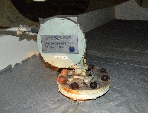
The top of the tank had originally been fitted with a float-type indicatorFootnote 56 that continuously transmitted information about the level of the tank to a monitor on the tank bulkhead. The monitor visually indicated the levels and sounded alarms in the ECR when the tank contents reached high or low levels (Figure 14). On the settling tank, the indicator had been fitted by a flanged connection to a pipe 10 cm in diameter that extended to the tank bottom. The wire and float for the indicator moved up and down inside this pipe. At some point, the indicator had been removed for repair or replacement, and the pipe opening had been covered with a blind flange.Footnote 57 The tank did not have a designated sounding pipe to take manual soundings.
In order to take a manual sounding, a crew member would need to climb onto the top of the settling tank, unbolt and remove the blind flange, sound the tank,Footnote 58 and bolt the blind flange back on. There was minimal space on top of the settling tank. At some point, the blind flange had been left off the pipe for ease of taking manual soundings. It is not known when the last manual sounding of the settling tank was taken. The engine room sounding log did not include records of manual soundings. It was also the crew’s practice to determine the level in the settling tank by manually running the transfer pump until it cut out at the high level and then estimating the quantity in the tank.
After the occurrence, a blind flange, 3 nuts, and 2 bolts were found on top of the tank near the indicator pipe opening (Figure 15).

The chief engineer recorded the quantity in the settling tank as 70 m3 on 18 January 2018 and 60 m3 on 22 January. On 24 January, the chief engineer recorded the quantity as 60 m3. The tank was sounded after the fire and was found to be at approximately 90 m3, approximately 83% of the total tank capacity.
Following the occurrence, samples of the contents from the settling tank were collected and analyzed by a private laboratory. This analysis indicated that the tank contained 7.7% freshwater, with a salinity of less than 2.0 parts per thousand.Footnote 59 The sample also indicated extensive dilution by LSMGO and other less volatile compounds.
1.10.3 Service tanks
The MOL Prestige had 2 service tanks used to supply LSMGO and HFO, respectively, to the main and generator engines. The HFO service tank, with a capacity of 113.2 m3, had an overflow pipe that connected internally to the settling tank, so that any overflow from the service tank went back to the settling tank.Footnote 60 The top of the tank had 2 air vents at opposite corners, which joined the same manifold as the settling tank air vents and terminated inside the funnel (Figure 12).
The HFO service tank was normally maintained at 85 °C. As with the settling tank, there was a local temperature gauge on the side of the tank and a high-temperature detector that sounded an alarm in the ECR when a temperature of approximately 90 °C was detected.
At the time of the occurrence, the temperature of the HFO in the service tank was reported to be 105 °C. Following the occurrence, the TSB examined the alarm logs from 15 January up until the time of the occurrence and found that the high-temperature alarm for the service tank had sounded on 26 January. However, there was no indication of what action had been taken in response.
The HFO service tank had originally been fitted with a float-type indicator that continuously transmitted information about the level of the tank to a monitor on the tank bulkhead. The monitor visually indicated the levels and sounded alarms in the ECR when the tank contents reached a low level. The alarm was set to activate when the level in the tank dropped to approximately 103 m3. Similar to its counterpart in the settling tank, the indicator, which was on top of the tank, was originally fitted by a flanged connection to a pipe. At some point, the indicator had been removed for repair or replacement, and the open pipe had been covered with a blind flange. The blind flange was secured over the pipe opening by 1 bolt. The remaining nuts and bolts were found lying on top of the blind flange (Figure 16).
In order to take a manual sounding, a crew member would need to climb onto the top of the service tank, unbolt and remove the blind flange, sound the tank, and bolt the blind flange back on. It is not known when the last manual sounding of the service tank was taken. The engine room sounding book did not include records of manual soundings. There was minimal space on top of the service tank, and an empty 5-gallon drum was placed there for sitting. The lighting was minimal, and a portable 220-volt lamp was kept on top of the tank.

The chief engineer had recorded the quantity in the HFO service tank as 90 m3 on 18 January 2018 and 70 m3 on 22 January. On 20 January, the engine room alarm records indicate that the HFO service tank low-level alarm had activated. At this time, the chief engineer had been checking the level-gauge components on the service tank because a partially opened valve in the purifier outlet manifold had diverted the HFO to the settling tank from the service tank. It was only after the overflow tank high level alarm had sounded and the service tank level was checked that the chief engineer realized that the service tank had emptied into the fuel oil overflow tank via the settling tank.
On 24 January, the chief engineer recorded the quantity as 70 m3. The tank was sounded after the fire and was found to be at 94.6 m3, which is 83% of the total tank capacity.
Following the occurrence, samples of the contents from the HFO service tank were collected and analyzed by a private laboratory. The results indicated a water content of 0.7% and a viscosity of 394 centistokes at 50 °C.
1.10.4 Overflow tank
The MOL Prestige had 1 overflow tank, which was used to catch both HFO and LSMGO from the settling and storage tanks if they were overfilled. The back flushing from the main engine and the generator diesel engine filter back flushing was also piped to this tank. The overflow tank, with a capacity of 111.7 m3, had 2 air vents that terminated on either side of the upper deck. The tank was fitted with a high-level indicator that sounded an alarm on the engine room panel when the tank capacity reached approximately 84.36 m3.
In October 2017, the engine room crew had encountered a situation in which the overflow tank was filling up at an abnormal rate. On 16 October, in the early morning, the overflow tank was sounded, and the quantity was recorded as 2.56 m3. In the early afternoon, a high-level alarm activated for the overflow tank; it was sounded again and found to be at 84.36 m3. The crew used a water-finding paste and determined that the tank was full of water. At that time, the chief engineer reported to BSM China that the steam heating coils in the overflow tank were leaking steam and water. BSM China instructed the chief engineer to transfer the contents of the overflow tank to bunker tank 7S.
In the evening, the crew put a cover on the steam inlet and outlet for the overflow tank to prevent the steam from passing through. The following morning, the crew sounded the tank again and found the contents to be 107.9 m3 of oily water mixture. Approximately 30 m3 of this mixture was transferred to bunker tank 7S, which at that time already contained 395 m3 of HFO. On 18 October, the chief engineer reported to BSM China that the contents in the overflow tank had increased by 9 m3 over a 7-hour timeframe. Between 18 and 23 October, approximately 56 m3 of water from the overflow tank was transferred to the bilge sludge tank and waste oil tanks. On 21 October, the overflow tank had 31 m3 of oily water mixture. The investigation could not establish if any corrective action was taken to resolve the issue.
On 05 January 2018, the overflow tank contents were recorded as 27.3 m3, increasing to 31.6 m3 by 08 January. The chief engineer reported to BSM China that the overflow tank had been presumably emptied into bunker tank 7S soon afterward.Footnote 61 On 18 January, the chief engineer reported to BSM China that the overflow tank contents were approximately 27.3 m3. The overflow tank was emptied again, but the tank level started increasing again until it was at 19.3 m3 on 20 January. On the same day, the overflow tank had inadvertently filled up during re-purification of the HFO service tank oil sounding the high level alarm. The tank was emptied a third time. On 22 January, the chief engineer reported to BSM China that the overflow tank contents were 5.92 m3. On 24 January, in preparation for taking on HFO in the bunker tanks, the overflow tank was emptied a fourth time,Footnote 62 and approximately 22 m3 of the contents were transferred to the settling tank. The level in the overflow tank again started increasing, reaching 10.5 m3 on 31 January, as recorded in the sounding book. The daily tank sounding log indicated that the crew regularly transferred the contents of the overflow tank to other tanks. The investigation established that the contents were not transferred to either the waste oil tanks or the sludge tank.
The investigation determined that the contents of the overflow tank had increased by approximately 19 m3 at the time of the occurrence. The overflow tank high-level alarm was not activated. Following the occurrence, the overflow tank contents were at 29.65 m3.
1.10.5 Drain tank
The MOL Prestige had 1 drain tank, with a capacity of 4.7 m3, that was used to catch both HFO and LSMGO leaks from equipment such as the main engines, generator engines, purifiers, and fuel pump casings. The tank was fitted with a high-level gauge that sounded an alarm on the engine room panel when the tank contents reached 4.0 m3.
The tank was connected to the HFO transfer pump’s suction manifold, which allowed the tank contents to be transferred to the settling tank or the bunker tanks. The vessel’s main engine high-pressure fuel pumps and pipes had a history of leaking LSMGO, and the LSMGO from these leaks was collected in the drain tank. Between 15 and 31 January, the pipes had leaked into this tank on several occasions. The drain tank high-level alarm had also sounded at least 9 times during this period. Leaks from the main engine fuel-injection system increased when the engines were operating on LSMGO. The contents of the drain tank were regularly transferred to the settling tank.
Between 19 and 28 January, approximately 8 m3 of HFO and LSMGO was transferred from the drain tank to the settling tank. Soundings after the occurrence indicated that the drain tank was full, at 4.7 m3.
1.10.6 Filter drain tank
The filter drain tank, with a capacity of 2 m3, collected the contents that drained from the filters of the main and generator engines. The tank was connected to the HFO transfer pump’s suction manifold, which allowed the contents of this tank to be transferred to the settling tank or the bunker tanks.
On 14 January, 1.5 m3 of LSMGO from the filter drain tank was transferred to the settling tank and, on 19 January, another 1.5 m3 was transferred.
1.10.7 Heavy oil purifiers
The MOL Prestige had 3 purifiers used to treat HFO from the settling tank and either send it to the service tank or return it to the settling tank. The purifiers could also receive HFO from the service tank. The purification process removed water and other impurities from the HFO. The resulting sludge was expelled into the sludge tank, and the operating water was expelled into a hopper.
The purifier throughput was set at approximately 3300 L per hourFootnote 63 for optimum purification. When the vessel was running on HFO, the normal practice was to have 2 purifiers operating simultaneously, which provided enough purified HFO to fill the service tank for consumption.
The temperature at the inlet to the purifier was usually kept at about 90 °C. The optimum temperature of the HFO for effective purification is 98 °C. A temperature higher than this makes the purifier operation unstable because the purifier loses its water sealFootnote 64 and, consequently, oil that is being purified drains into the sludge tank; this phenomenon is commonly referred to as “purifier dumping.” At the time of the occurrence, the temperature at the inlet to the purifier in use was around 110 °C. The purifier was losing its water seal and was constantly dumping. The operating water hopper was emitting steam and oil fumes.
Between 20 and 22 January, the No. 2 purifier was in operation for 39 hours and the No. 3 purifier was in operation for 27 hours. The No. 1 purifier was not in operation during this time, but operated for 1 hour each on 27 and 28 January. At 0624:22 on January 28, the high-temperature alarm for the No. 1 purifier sounded. The TSB could not determine if the HFO settling tank temperature was checked or whether any other action was taken as a result of the alarm.
1.10.8 Fuel transfer pumps
The MOL Prestige had 2 fuel transfer pumps, each with a flow rate of 90 m3 per hour. One was dedicated to transferring HFO among the various tanks, and the other to transferring LSMGO.
The HFO pump had automatic and manual modes. In automatic mode, float switches on the settling tank controlled the starting and stopping of the transfer pump based on the level of the contents in the settling tank. In 2011, the high-level float switch for stopping the pump had been modified so that it would also function when the pump was set to manual mode.Footnote 65
At some point in the past, the engine room crew had experienced a situation while using the HFO pump in manual mode to transfer HFO to the settling tank. During the transfer, the high-level cut-out had stopped the pump, rendering it inoperative until the settling tank contents were transferred and the level reduced below the cut-out. At the same time, the high-level alarm for the drain tank had sounded. Before they could operate the pump to reduce the contents in the drain tank, the engineers first had to lower the settling tank level, to render the pump operative again, among other reasons.
Post-occurrence, the investigation determined that even if the pump had been left on for the duration of 15 minutes (between 2110 until 2125), it would have only pumped in 22.5 m3 before the vessel lost all electrical power.
1.11 Other engine room equipment
1.11.1 Auxiliary boiler
The auxiliary boiler was fuelled by LSMGO and could produce steam at a maximum pressure of 7 bars. The auxiliary boiler was not in operation at the time of the occurrence, because the exhaust gas economizer was operating.
The auxiliary boiler produced saturated steamFootnote 66 using water pumped in from the cascade tank. The steam was used for various purposes on board, such as heating the steam coils that passed inside the settling, service, and bunker tanks. The steam was also used in tracing lines that ran along the pipes used to transfer HFO, in order to keep the HFO warm in the pipes.
The TSB determined that there were various leaks in the steam system, including leaks from the flanges and connections in the tracing lines. The water from these leaks drained into the engine room bilges. BSM China had instructed the chief engineer to reduce the auxiliary boiler pressure to 5 bars while the vessel was slow steaming or in port in order to reduce fuel consumption.
The investigation determined that the cascade tank, which provides water to the auxiliary boiler, was being manually filled during the month of January with approximately 100 L of freshwater per day.
1.11.2 Exhaust gas economizer
The exhaust gas economizer is a boiler that creates steam using heat from the exhaust gases of the main engine. The economizer produced saturated steam at a maximum pressure of 7 bars. Any excess steam pressure was diverted to a dumping valve. The steam was piped to the auxiliary boiler steam drum.
1.12 Overflow of fuel oil from the settling tank
A number of studies have investigated the frothover phenomenon in storage tanks containing crude oil or certain types of heavy fuel oils.
The National Fire Protection Association defines frothover, which is not associated with fire in the tank, but happens when water is present or enters a tank containing hot, viscous oil. Upon mixing, the sudden conversion of water to steam causes a portion of the tank contents to expand in volume and overflow the tank.Footnote 67
In this occurrence, approximately 20 m3 of oily water mixture, at a temperature of between 7 °C and 30 °C, was transferred from bunker tank 7S to the settling tank, which was at a temperature of 120 °C. These conditions are conducive to frothover.
1.13 Observations during TSB visits to the MOL Prestige and the MOL Prosperity
Following the occurrence, TSB investigators made 2 visits to the MOL Prestige. They also visited the MOL Prestige’s sister vessel, the MOL Prosperity, on 12 February 2018.
1.13.1 First visit to the MOL Prestige (2018)
On the first visit to the MOL Prestige in 2018, the TSB investigators made the following observations:
- A blind flange was secured by one bolt over the sounding pipe opening to the HFO service tank.
- A blind flange was lying on top of the HFO settling tank, and the sounding pipe opening to the settling tank was open to the atmosphere.
- Both sides of the blind flange, and the inside of the sounding pipe, on the settling tank were thermally damaged.
- A portable compact fluorescent lamp (damaged) was positioned on the top of the HFO service tank. The lamp was examined by the TSB Engineering Laboratory.
- The settling and service tanks’ ventilation pipes led to a common manifold opening in the funnel, which was about 30% plugged with debris.
1.13.1.1 TSB laboratory examination of the portable lamp
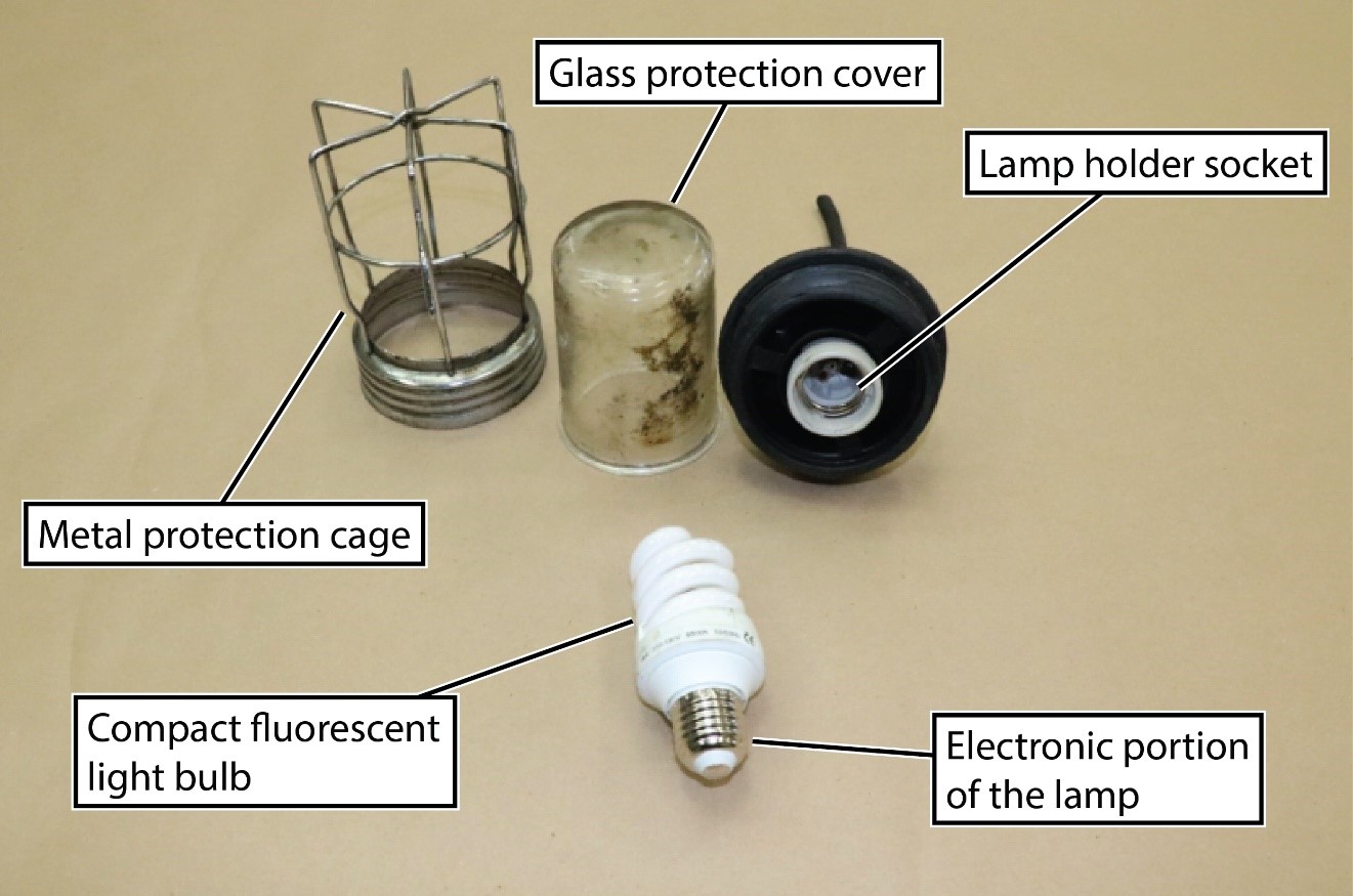
The TSB Engineering Laboratory in Ottawa, Ontario, examined the portable lamp positioned on top of the HFO service tank to determine whether it was the cause of the fire.Footnote 68 The lamp was not powered at the time of the occurrence. Various items—such as the lamp wiring, the electrical pin sockets, and the lamp holder socket—were checked for signs of arcing. None was found.
The TSB Engineering Laboratory also conducted tests to monitor the temperature of various components on a replica lamp, including the compact fluorescent lightbulb, the electronic portion of the lamp, the lamp holder socket, the glass protective cover, and the metal protective cage (Figure 17). These tests were conducted in both open-air and enclosed environments, and the temperature was measured starting from 30 minutes to 6 hours into the testing. The temperature of the compact fluorescent lightbulb remained constant at 61 °C, and the temperature of the electronic part of the lamp remained constant at 42 °C. The glass protective cover had an average temperature of 55.25 °C, and the metal protection cage had an average temperature of 25.67 °C.
1.13.2 Visit to the MOL Prosperity (2018)
On 12 February 2018, TSB investigators boarded the sister vessel MOL Prosperity and checked the temperatures of the HFO in the service and settling tanks. The temperature of the HFO in the service tank was 112 °C, and the temperature of the HFO in the settling tank was 92 °C. Adjacent to both local gauges was a handwritten notation indicating that the maximum tank temperature was to be maintained at 90 °C. The high-temperature set point for the remote temperature indicator was at 110 °C for the settling tank and at 115 °C for the service tank. The engine room alarm panel indicated the temperatures as “normal.”
The level indicator for the settling tank indicated that the tank level was approximately 82.0 m3. The high-level set point for the high-level alarm was at 102 m3 and the low-level set point for the low-level alarm was at 45.0 m3. The engine room alarm panel indicated a “high” level.
The investigators also noted that the steam controller bypass valves for the settling tank steam heating coil on the MOL Prosperity were leaking, similar to those on the MOL Prestige.
1.13.3 Second visit to the MOL Prestige (21 February 2019)
The blowdownFootnote 69 valve on the auxiliary boiler on Deck 3 was found to be not insulated and indicated a temperature of 139.5 °C on the exposed part.
The blowdown valve was located approximately 1 m from the settling tank and approximately 4 m below the settling tank top (Figure 18).

When the vessel was operating on emergency lighting, the underdeck passages were not lit, with the exception of 1 emergency light above each of the doors leading into the engine room.
1.14 Fire pattern analysis for origin and ignition source
A fire pattern analysis can help establish how and where a fire started and how it spread by looking at how materials have been changed as a result of exposure to fire.Footnote 70
A fire investigator assisting the U.S. Coast Guard conducted a fire pattern analysis of the engine room using National Fire Protection Association guidelines. The investigator’s analysis shows that the fire travelled from the third deck to the second deck, as indicated on Figure 19. The investigator identified that “the more severe thermal damage [was] on the upper level of the 3rd deck and move[d] up to the 2nd deck and follow[ed] the two pipes to the overhead.”Footnote 71 The report also identified that oil had overflowed onto deck 3 in the engine room.
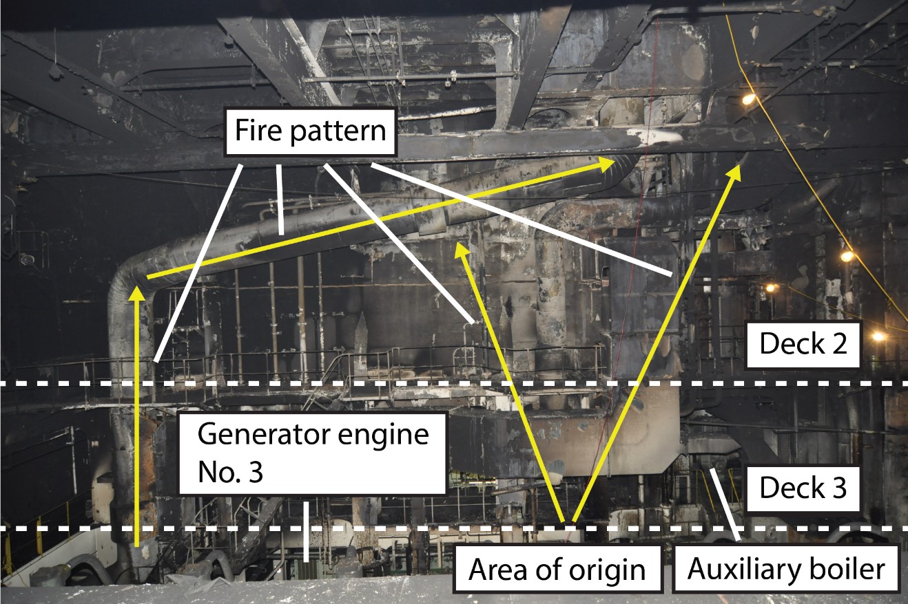
Information gathered from the CCTV footage indicated that oil was initially expelled from the settling tank through the open level indicator pipe, and fell onto decks 3 and 4 and onto the oily water separator on the bottom deck. The fire then started on deck 3 between the auxiliary boiler and the settling tank, where there was evidence of heat sources, including uninsulated steam lines, the exhaust manifold for generator engine No. 3, and electrical fittings.
Fire patterns determined that this was the area of origin of the fire. Soon after, the burning oil then flowed down to deck 4 near generator engine No. 3 and onto the bottom deck near the oily water separator. The fire also travelled back to the top of the settling tank, where the bulk of the spilled oil was located. This became the seat of the fire fuelled by the HFO overflowing from the level indicator pipe on the settling tank.
1.15 International guidance on preventing engine room fires
The IMO has developed guidelines for measures to prevent engine room fires.Footnote 72 The guidelines are intended for use by vessel owners, designers, masters, inspectors, and surveyors.
The guidelines state that oil fuel in storage tanks should not be heated to temperatures within 10 °C below the flashpoint of the oil fuel and further specify that oil fuel in service tanks, settling tanks, and any other tanks in the supply system may be heated above this limit only if certain conditions are met. Among other things, these conditions include the following:
- The vent pipes from such tanks are of sufficient length to cool the vapours to at least 10 °C below the flashpoint of the oil fuel.
- The vent pipes from oil fuel tanks and heated lubricating oil tanks lead to a safe place on an open deck and do not terminate in any place where a risk of ignition is present.
- The vent pipes are fitted with temperature sensors that will activate an alarm if the temperature should exceed 10 °C below the flashpoint of the oil fuel.
- The vent pipes are fitted with flame screens that meet IMO requirements.Footnote 73
- There are no openings from an oil fuel tank’s vapour space into machinery spaces, although bolted manholes are acceptable.
- Electrical equipment fitted in an oil fuel tank’s vapour space is certified to be intrinsically safe.Footnote 74 ,Footnote 75
With respect to sounding pipes, the IMO guidelines state that they “should not terminate in any space where the risk of ignition of spillage from the sounding pipe might arise. […] As a general rule, they should not terminate in machinery spaces.”Footnote 76
The classification society Lloyd’s Register also has rules about situations in which oil fuel is heated above a temperature exceeding 10 °C below its flashpoint.Footnote 77 ,Footnote 78 Many of the rules incorporate the IMO guidance, but Lloyd’s Register also specifies the following:
- Openings in the drainage systems of tanks containing heated oil fuel are located only in spaces where oil vapours at temperatures close to the flashpoint cannot accumulate.
- There are no sources of ignition in the vicinity of the ventilation pipes, or near the openings in the drainage systems, or in the tanks themselves.
- The temperature of any heating medium is not to exceed 220 °C.Footnote 79
1.16 Fire detection system
The fire detection system on the MOL Prestige consisted of heat, smoke, and flame detectors. The vessel was divided into zones that covered the various decks and areas on the vessel. The vessel’s fire control plan indicated that, in the engine room, there were 47 smoke detectors, 9 flame detectors, and 6 temperature detectors. The fire control plan also indicated 19 smoke detectors in the vessel’s superstructure. The vessel’s fire detection system was routinely tested every Saturday.
1.16.1 Fire alarms
The fire alarm panel on the bridge indicated the various zones. When a detector activated, the zone illuminated on the panel and an audible alarm sounded. The panel did not indicate the type of detector (smoke, flame, or heat) that had activated the fire alarm.
By contrast, the fire alarm panel in the engine control room indicated a generic fire alarm but did not indicate the zone or type of detector that had activated the fire alarm.
At the time of the occurrence, the first fire alarm that sounded was for zone 9. The alarm was triggered by a smoke detector on the engine casing. After that, the following fire alarms sounded in rapid succession:
- Zone 10 (triggered by smoke detectors on deck 2)
- Zone 11 (triggered by smoke detectors on deck 3)
- Zone 12 (triggered by smoke detectors on deck 4)
- Zone 19 (triggered by a flame detector for diesel generator No. 3)
- Zone 20 (triggered by a flame detector for diesel generator No. 4)
- Zone 16 (triggered by 2 flame detectors over the main engine)
Almost an hour later, the fire alarm for zones 1, 3, 4, 5, and 6 sounded. These zones covered the accommodation decks F, D, C, B and A, respectively. These decks were not affected by the fire, but the alarms were triggered by smoke from the engine room. The smoke reached these decks through the engine room doors, which were opened intermittently to fight the fire.
1.17 Emergency response standards and procedures
With respect to emergency response standards and procedures, the ISM Code specifies that a company should
- identify potential emergency shipboard situations and establish procedures to respond to them; and
- establish programs for drills and exercises to prepare for emergency actions.Footnote 80
The procedures required by the ISM Code should be documented and compiled in a safety management manual, a copy of which should be kept on board.
1.17.1 MOL Prestige’s fire response procedures
The MOL Prestige had a safety management manual, vessel-specific manuals, and an emergency response manual (ERM) on board. The MOL Prestige’s ERM contained information about initial actions to be taken by the crew in an emergency and about notifications, as well as procedures for a number of emergencies, including fire on board the vessel, fire and explosion in the engine room specifically, and rescue from an enclosed space.
According to the ERM, initial crew actions when the alarm sounds should be prioritized as follows:
- When the alarm sounds:
- Go to the muster station
- Take a headcount
- Report to bridge
- Identify type of emergency
- Start emergency response
- Start record keepingFootnote 81
When the crew have identified the emergency as a fire in the engine room, the crew are required to respond in the following sequence:
- Stop all cargo operations, fuel oil transfers, and lubricating oil transfers.
- Consult the Marine Safety Data Sheets for emergency measures.
- Identify the location and class of fire, method of extinguishing fire, risks, then injured persons.
- Isolate electrical power to affected space.
- Ensure operation of the emergency generator, fire pumps, emergency fire pump, fixed firefighting systems.
- Start firefighting, send firefighting teams, stop all ventilation to affected space, start boundary cooling.
- Rescue injured persons.
- Send distress message and distress alert.Footnote 82
If an emergency necessitates rescue from an enclosed space, the rescue team is required to identify the number, position, and condition of the persons in the enclosed space and don lifesaving equipment. The ERM clearly warns that no person should ever “enter an enclosed space without proper rescue preparations and support/back-up.”Footnote 83 When crew members sign on to the vessel, they must be familiarized with the escape routes from the engine room and their place of work.
The ERM does not specify who should conduct the activities involved in a rescue from an enclosed space, nor the location where they should be conducted. The MOL Prestige had general fire instructions posted on its fire muster list. According to the instructions, all crew members should be accounted for and mustered before any firefighting activities begin. If no one is missing, the fresh-air supply to the affected place should be cut off, under instructions of the chief officer or second engineer.
1.17.2 Crew response to fire alarms
Alarm systems alert a crew to unexpected events or critical information that require immediate attention or action. Quick and appropriate response to fire alarms aboard ship is particularly important to limit the spread of fire and minimize significant damage to the vessel and risks to persons aboard the vessel. Repeated false alarms may cause occupants to become desensitized and to start ignoring alarms, thinking they may be false.Footnote 84 Desensitization can lead to longer response times or to missing important alarms.
When activated, fire alarms aboard the MOL Prestige sounded on the bridge, in the ship’s office, and in the ECR. Because the fire detection system included fire, heat, and smoke sensors, it could inadvertently be activated by benign sources of smoke or heat, such as welding fumes and steam leaks.
Before the occurrence, the vessel had experienced various fire alarms in the engine room as a result of smoke and heat sources unrelated to a fire. On 19 August 2017, a generator breakdown resulted in excessive steam in the engine room, which activated the fire alarm. The vessel’s report to BSM China about the incident indicated that this happened twice in the same day.
On a different occasion, the fire alarm was activated when the incinerator doors were opened while the incinerator was running, which caused smoke to fill the engine room. The engine room alarm log indicated that a fire alarm had sounded on 24 January 2018 at 1051 and was silenced at 1055. The alarm had also sounded on 28 January at 0624.
In response to these alarms, the crew had been asked to investigate the source of the alarm before mustering according to the shipboard procedure. Once the source of the alarm was established, the crew notified the master and the master determined whether the source warranted sounding the general alarm.
Not all of the crew on the MOL Prestige mustered immediately in response to the general alarm. Crew members who had not initially responded mustered at their designated fire stations only when the master made an announcement on the public address system about the fire.
1.18 Means of escape
1.18.1 SOLAS requirements
The MOL Prestige was constructed in 2006 in accordance with the SOLAS requirements in effect. At that time, the requirements specified that 2 means of escape were to be provided from each machinery space of category A.Footnote 85
In 2014, SOLAS set out new requirements for cargo vessels constructed on or after 01 January 2016 regarding escape from machinery control rooms in machinery spaces.Footnote 86 ,Footnote 87 For escape from machinery control rooms (including engine control rooms) and main workshops in machinery spaces of category A, the regulation specifies that
Two means of escape shall be provided from the machinery control room located within a machinery space. At least one of these escape routes shall provide a continuous fire shelter to a safe position outside the machinery space.Footnote 88
Because the MOL Prestige was constructed in 2006, it was not subject to these regulations.
Current SOLAS requirements require A-60 divisions for “control stations”Footnote 89 (except in the case of vessels propelled by liquefied natural gas), but the definition of a control station in these requirements does not include engine control rooms that are in machinery spaces. Therefore, engine control rooms that are in machinery spaces are not required to have A-60 divisions.
Current SOLAS requirements also indicate that escape routes and additional aids for escape, such as clear markings, “shall be provided so that persons on board can safely and swiftly escape an emergency situation to a safe location. Elevators are not considered a means of escape.”Footnote 90
The IMO has guidelines for evacuation analysis that apply to passenger vessels, although they are not required for cargo vessels such as the MOL Prestige. An evacuation analysis is done to evaluate escape routes during vessel design. Among other things, the guidelines specify that
the analysis shall be used to demonstrate that escape arrangements are sufficiently flexible to provide for the possibility that certain escape routes, assembly stations, embarkation stations, or survival craft may not be available as a result of a casualty.Footnote 91
1.18.2 Means of escape from the engine room
There were 9 means of escape from the engine room on the MOL Prestige. Three doors located on deck 2 provided a means of escape to the upper deck (doors 49, 50, and 51) via stairs. Two additional doors located on the port and starboard sides of the engine room led to the underdeck passage via stairs. A series of ladders and platforms in the engine room casing provided another means of escape that led from deck 2 to deck C or the monkey island. Lastly, there was an emergency escape from the bottom deck through the shaft tunnel to the steering gear room.
While not considered a means of escape, the elevator could also be used to enter and exit the engine room from deck 2 or deck 3. On the sister vessel, the MOL Prosperity, the elevator has a sign indicating that it is not to be used in the case of a fire. The elevator on the MOL Prestige did not have such a sign installed.
At the time of the occurrence, all of the doors were closed and were free from obstructions. The engine room crew normally entered and exited the engine room using the elevator, because it was the most direct route between the engine room and the upper decks.
1.18.3 Means of escape from the engine control room
The ECR was located on the lower of the 2 levels on the port side of the vessel, with no direct means of escape to a location outside of the engine room. The ECR was a self-contained room with 3 doors. One door was located on the port side of the ECR and was closest to the port side access to the underdeck passage from the engine room. The 2 remaining doors were located closer to amidships, with one being adjacent to the elevator and the other adjacent to the stairs leading to door 51 on the upper deck.
The closest exit from the engine room was the door to the port underdeck passage. The second-closest exit was door 51. Doors 49 and 50, as well as the door to the starboard underdeck passage, were approximately 20 m from the ECR (Figure 20).
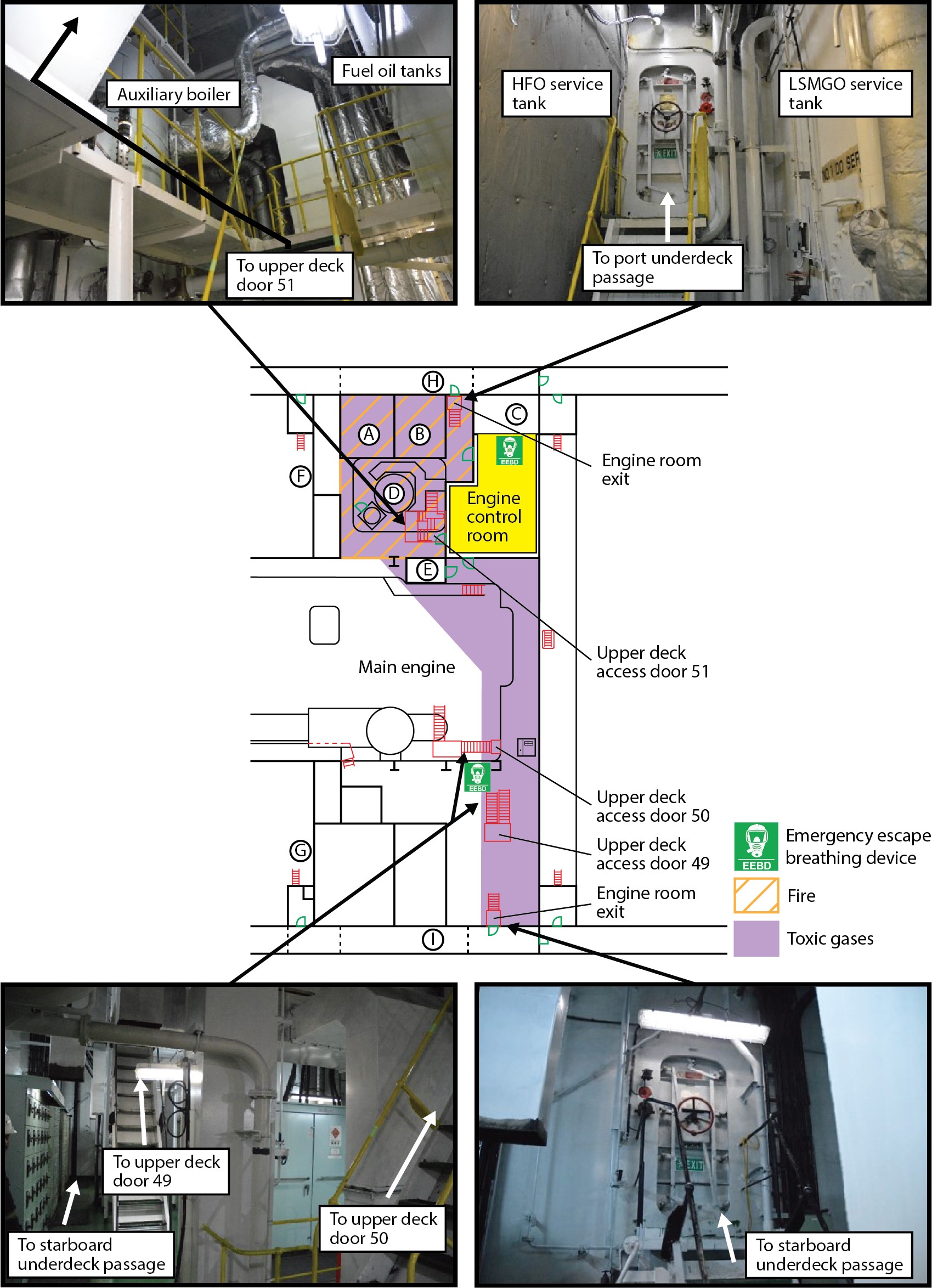
Legend
A HFO settling tank
B HFO service tank
C LSMGO service tank
D Auxiliary boiler
E Elevator
F Cargo hold No. 8 (port)
G Cargo hold No. 8 (starboard)
H Underdeck passage (port)
I Underdeck passage (starboard)
At the beginning of their watch, the crew would typically first enter the ECR using the elevator. Although the crew knew about the other exits, they rarely used them as part of daily activities. During shifts, the ECR was the usual place the engine crew gathered when they needed to have a face-to-face discussion away from the noise of the engine room machinery. When the engine room crew tried to exit the ECR, all means of escape were engulfed in thick black smoke and exposed to high heat from the fire near the auxiliary boiler and the HFO settling and service tanks.
1.18.4 Exit door visibility
The 6 exit doors in the engine room were painted white (the same colour as the surrounding walls) and marked with luminescent green exit signs. Fluorescent lighting placed directly above the doors provided illumination for all exit doors. None of the exit doors from the engine room could be seen from inside the ECR. The emergency escape route via the shaft tunnel was indicated by emergency escape signs posted near the stairs on decks 2, 3, 4, and the bottom deck, and the route was indicated by arrows and stenciled emergency escape signs on the pillars in the engine room.
When the emergency generator came online, the emergency lighting would automatically activate. Emergency lighting illuminated a reduced number of lights in the engine room and throughout the rest of the vessel.
1.19 Fire muster list
IMO states that “clear instructions to be followed in the event of an emergency shall be provided for every person on board,” and that every person should also have a duty on the muster list.Footnote 92 The muster list must indicate key personnel and their substitutes, assign emergency duties to each individual crew member, and assign muster stations for each person on board, including passengers and supernumeraries. The muster list must be posted in the wheelhouse, in passageways on all decks, in the mess room, and in the engine control room.
The fire muster list on the MOL Prestige was posted in the required locations and specified the teams, leaders, and main duties of each crew member in the event of a fire.Footnote 93 The muster list did not identify substitutes for key positions (Figure 21).
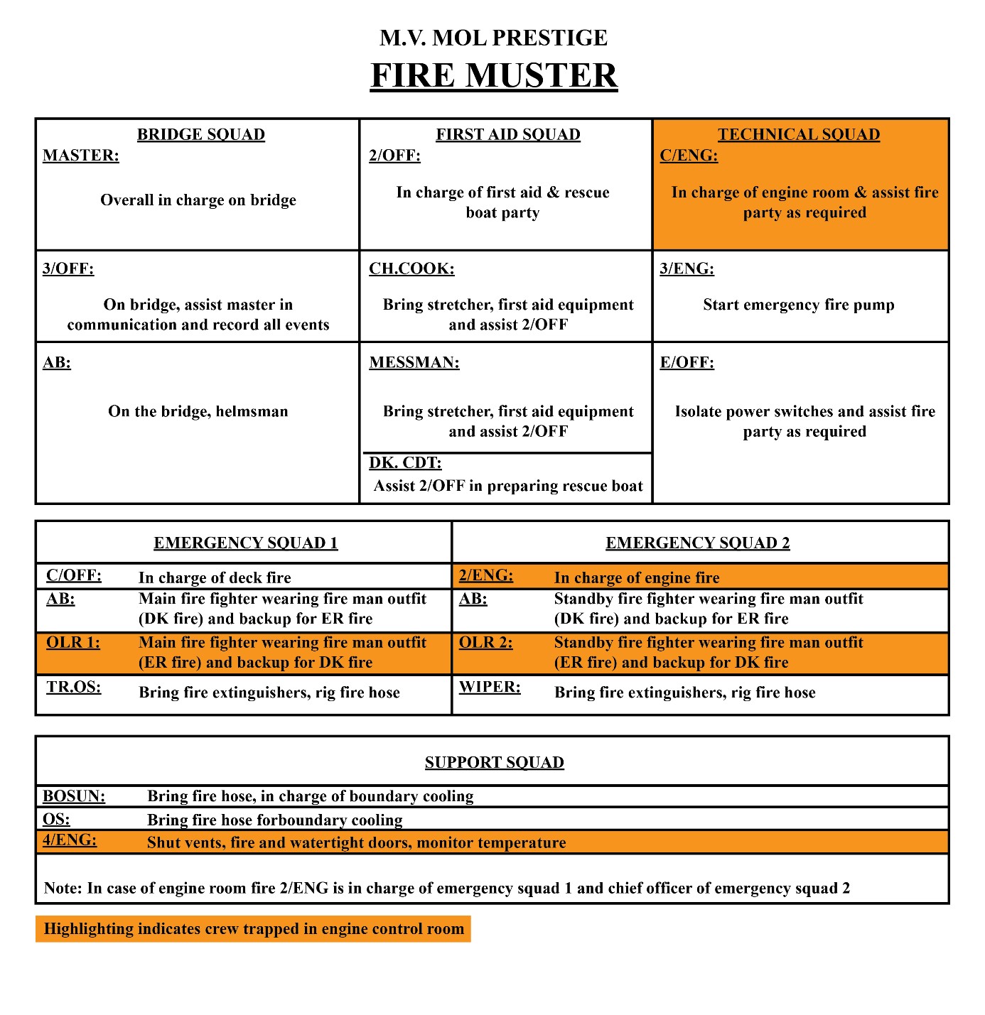
Legend
2/OFF Second officer
C/ENG Chief engineer
3/OFF Third officer
CH.COOK Chief cook
3/ENG Third engineer
AB Able seaman
DK.CDT Deck cadet
E/OFF Electro-technical officer
C/OFF Chief officer
2/ENG Second engineer
OLR 1 Motorman 1
OLR 2 Motorman 2
TR.OS Trainee Ordinary seaman
OS Ordinary seaman
4/ENG Fourth engineer
In the case of an engine room fire, the second engineer is in charge of emergency squad 1, which is the main firefighting squad. Motorman 1 is the designated firefighter, while one of the able seamen is the backup. Both are required to don firefighting suits during a fire of any type. Emergency squad 2 is the standby firefighting squad if crew members from emergency squad 1 are not available at the muster station. The other able seaman and motorman 2 are the standby firefighters for engine room fires. The wiper’s fire duties consist of bringing the fire extinguishers and rigging fire hose.
At the time of the occurrence, the chief engineer, second engineer, fourth engineer, motorman 1, and motorman 2 were trapped in the ECR, preventing them from performing their assigned roles as stated on the fire muster list.
The junior engineer was not included on the fire muster list. Following the occurrence, the junior engineer was added to the support squad. The main muster list indicates a position for a junior engineer without fire duties assigned.
The designated muster station for engine room crew was the fire station located on the upper deck.
1.20 Firefighting and lifesaving equipment
The MOL Prestige was equipped with all of the required firefighting and lifesaving equipment required under SOLAS Regulation 13, Chapter II-2. The vessel had 2 firefighter outfits and 2 SCBAs, one stored in a locker on deck D and the other stored at the fire station on the upper deck. Each outfit consisted of a rigid helmet, protective clothing, boots and gloves, a waist belt, a fire axe, a battery-operated safety lamp, and a fireproof life line. The vessel also had 2 spare SCBAs and 4 sets of chemical-resistant protective clothing, located in a locker on deck D.
1.20.1 Emergency escape breathing devices
IMO requires that “on all ships, within the machinery spaces, EEBDs shall be situated ready for use at easily visible places, which can be reached quickly and easily at any time in the event of fire.”Footnote 94 The number and location of EEBDs must be indicated in the fire control plan. The location of the devices should also take into account the layout of the machinery space and number of persons normally working in the spaces. The IMO states that
[c]onsideration should be given for placing such devices along escape routes within the machinery spaces or at the foot of each escape ladder within the space. In addition, control spaces and workshops located within the machinery spaces should also be considered for the possible location of such devices.Footnote 95
The vessel was equipped with 10 emergency EEBDs, each providing 15 minutes of air supply. The vessel’s fire control plan indicated that there were 6 EEBDs in the engine room and 4 above deck. They were located as follows:
- Deck 2: two in total, 1 in the ECR and 1 next to the stairs to door 49
- Deck 3: two in total, 1 in the workshop (located below the ECR) and 1 aft of the vessel near the stairs up to deck 2 or down to deck 4
- Deck 4: one located aft of the vessel near stairs to the deck above
- Bottom deck: one located aft of the vessel near stairs to the deck above
- Two at the fire station
- Two spares, 1 at the fire station and 1 at the navigation bridge locker
The vessel was also equipped with various portable fire extinguishers and fire hydrants with hose and nozzle.
1.20.2 Fixed fire suppression systems
1.20.2.1 Carbon dioxide
CO2 is the most commonly used medium for extinguishing fires on board vessels. CO2 extinguishes fires by displacing oxygen in the atmosphere to a point where it will not support combustion. It is a clean medium and does not leave any residue behind. However, it begins to be lethal to humans in concentrations of 17% by volume or more;Footnote 96 releasing it into a confined space will cause death to any people present in that space.
The vessel had a fixed fire suppression system consisting of 434 cylinders of CO2 that weighed 45.4 kg each. The cylinders were located in a CO2 room at the stern of the vessel (Figure 22).
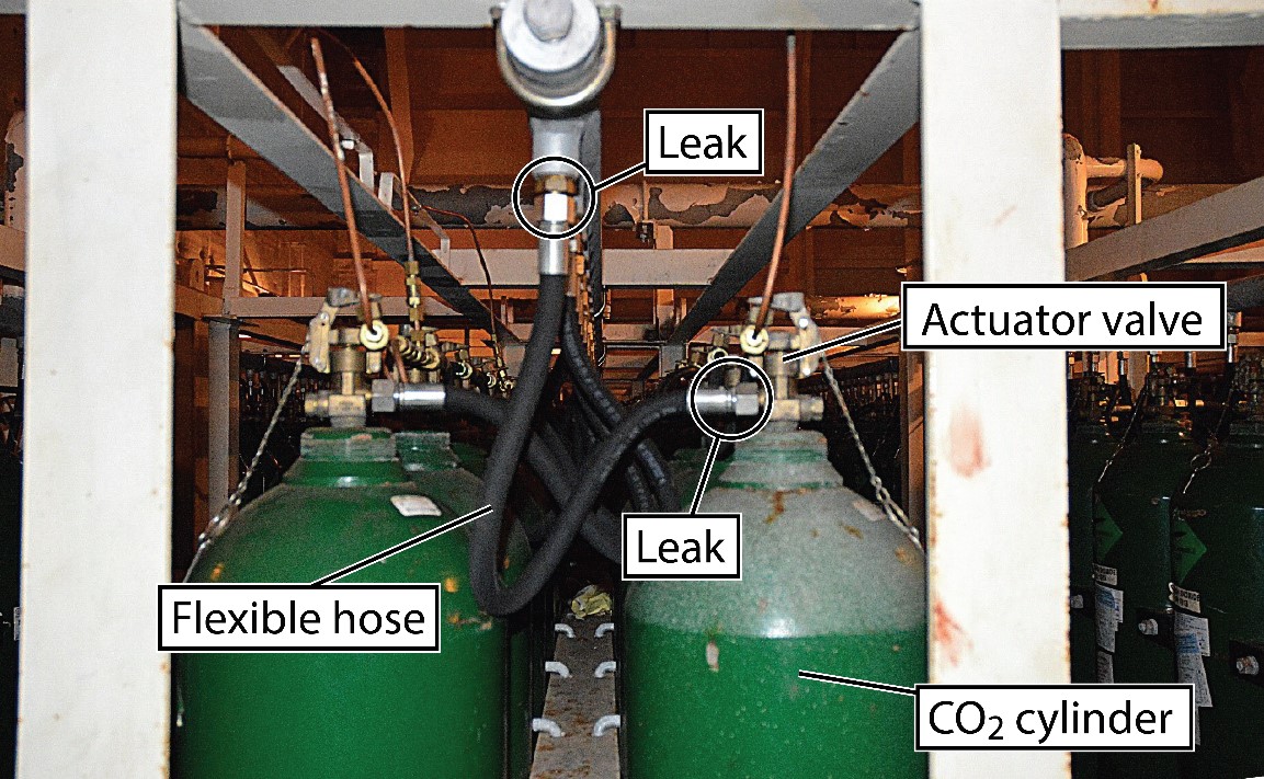
The system could be used for fires in either the cargo hold or engine room. To suppress a fire in the engine room, fans needed to be stopped, all vents needed to be closed and then 312 cylinders were required to be discharged within 2 minutes. The system had a remote-control release located at the fire station. The engine room was fitted with 53 nozzles, which were designed to release the CO2 at various places in the engine room simultaneously. There was 1 nozzle in the ECR (Figure 23).
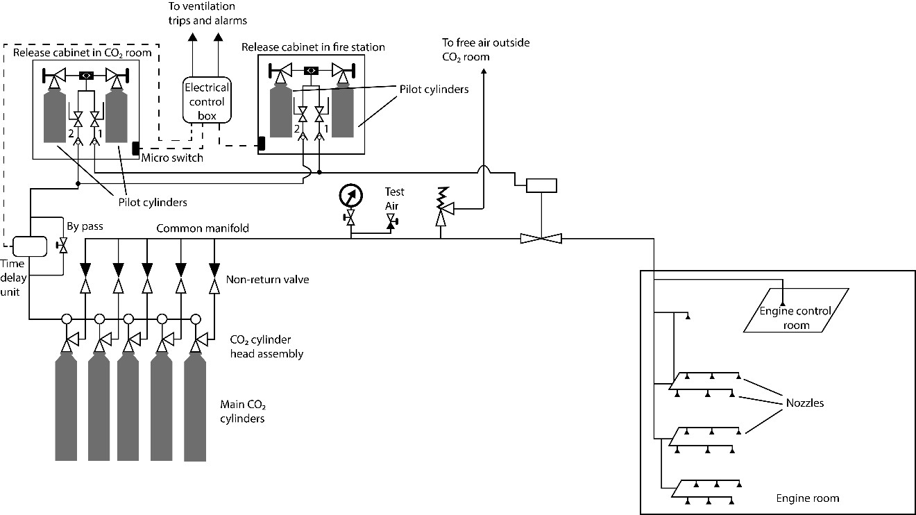
On the MOL Prestige, the chief engineer would activate the CO2 fire suppression system on the master’s order.
To release CO2 into the engine room, the crew must take the following actions:
- Open the remote-release cabinet door at the fire station, which sounds an alarm and automatically trips the electrical circuits for various equipment, including the ventilation.
- Open pilot cylinder valve and then valve 1 and valve 2 in the remote cabinet.
At this point, gas in the pilot cylinder is piped into a time-delay unit in the CO2 room and then to the various CO2 cylinders. Each CO2 cylinder is fitted with a valve that can be opened by the pressure of the gas from the pilot cylinder. The valves are connected by a small-bore pilot loop to the gas inlet ports of the pressure actuators, which allows for the simultaneous release of all cylinder valves. The CO2 from the individual cylinders is then piped into a common manifold via a flexible hose.
If the CO2 cylinders do not discharge when the pilot cylinder valve in the remote cabinet is opened, crew are instructed to open the individual valves for the cylinders manually using the manual handle.
1.20.2.2 Inspection and maintenance
For the maintenance and inspection of fixed CO2 fire extinguishing systems, IMO has developed guidelinesFootnote 97 ,Footnote 98 to ensure the reliability of firefighting systems and appliances. The guidelines state that
[f]ixed carbon dioxide fire-extinguishing systems should be kept in good working order and readily available for immediate use. Maintenance and inspections should be carried out in accordance with the ship’s maintenance plan and […] included in the ship’s safety management system and based on the system manufacturer’s recommendations including:
- maintenance and inspection procedures and instructions;
- required schedules for periodic maintenance and inspections;
- listing of recommended spare parts; and
- records of inspections and maintenance, including corrective actions taken to maintain the system in operable condition.Footnote 99
The guideline requires monthly and annual inspections, as well as the minimum recommended maintenance at each intermediate, periodic or renewal survey for cargo ships.Footnote 100
One of the maintenance inspections, to be carried out by an authorized service technician/specialist during the renewal survey, involves checking for possible leakages by applying full working pressure through the pilot lines and testing the manifold.
The system on the MOL Prestige was last serviced in May 2016, when it was inspected in accordance with the IMO guidelines. The inspection included hydrostatically testing the cylinders and inspecting the pilot cylinder. The flexible hoses were tested and renewed; the time-delay devices were tested; and the system control valve was inspected. However, the system manifold and distribution lines, which are items on the technician’s checklist, were not tested.
A post-occurrence inspection of the vessel’s fixed fire suppression system was carried out by an external contractor. The inspection found that some of the 312 cylinders had not released into the engine room as they were designed to do during the occurrence. The contractor’s report identified the following:
- A fitting that connected the line from the time-delay unit to the actuation lines of the engine room cylinders was loose where it was secured on the time-delay unit and was leaking heavily in the CO2 room.
- As a result of the leak, at least 70 cylinders furthest from the time-delay unit were deprived of the necessary actuating pressure, and these cylinders did not release their CO2.
- Two of the check valves in the actuation line were leaking inside the CO2 room.
- Copper tubing runs from the remote-release cabinets at the fire station, through the engine room, to the CO2 room; this tubing was damaged.
- A number of copper packings were missing from the CO2 cylinder hoses, and the hoses were leaking CO2 in the CO2 room (Figure 24).
- The stop valve for the main engine room was leaking.
- The crew manually released 84 cylinders (Figure 25), which included some cylinders marked for the cargo holds.
- A total of 258 cylinders were used to fight the fire.
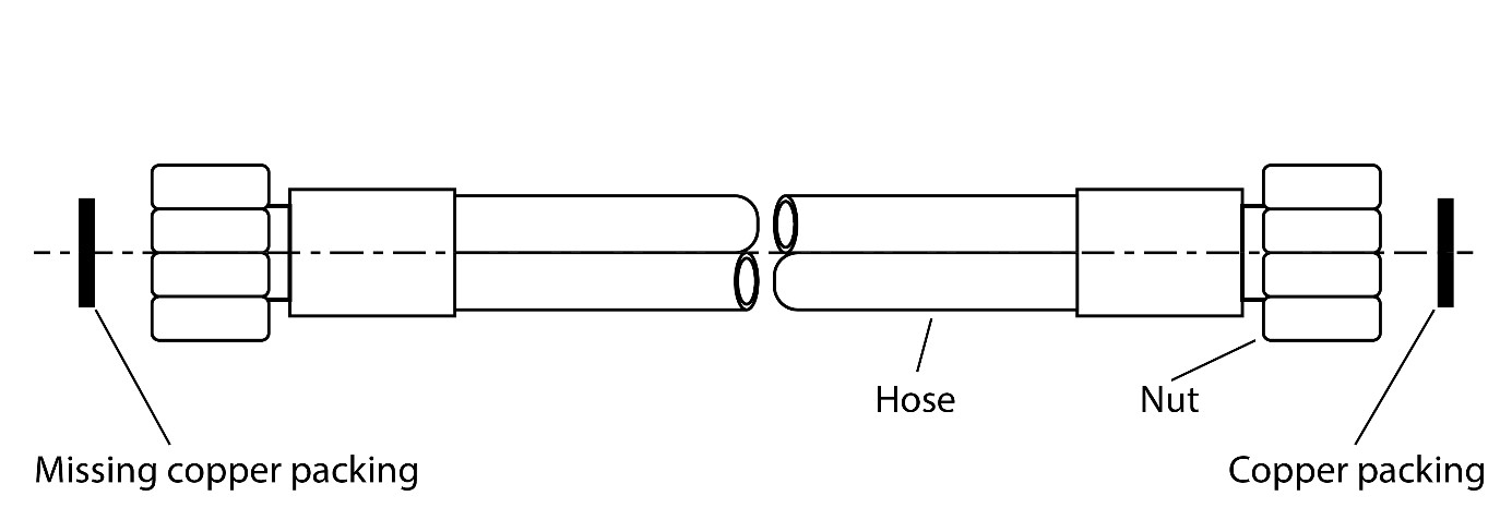
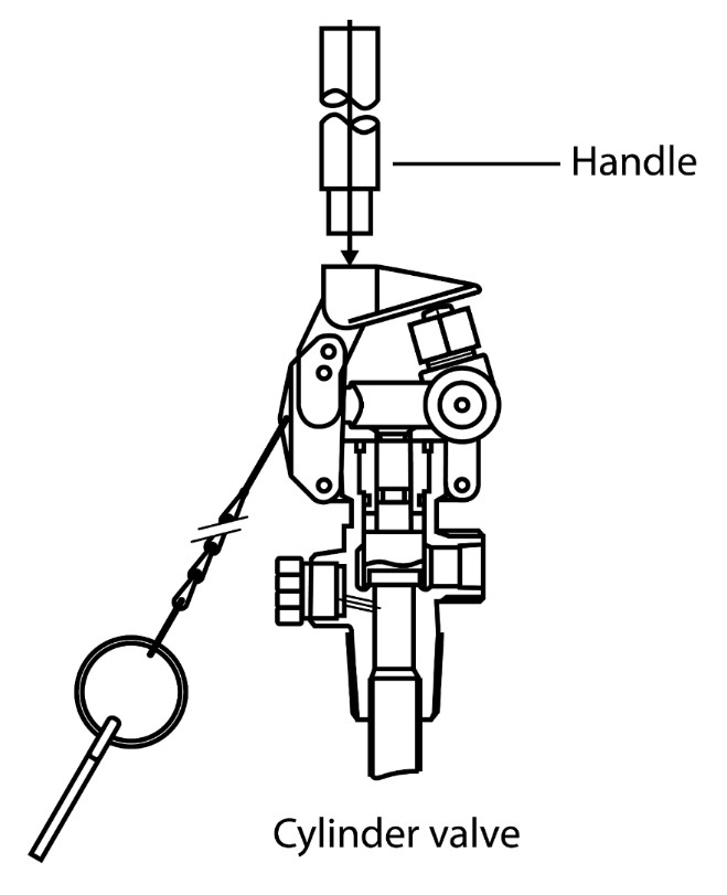
At the time of the occurrence, the master did not know that some of the 312 cylinders had not released as intended. The TSB determined that 174 cylinders of the 312 had been released remotely.
The contractor advised BSM China to overhaul the main stop valve for engine room and clean all the nozzles. After the occurrence, 218 cylinders were hydrotested and 258 cylinders were refilled.
1.20.2.3 Water-mist fire suppression system
The vessel was fitted with a water-mist fire suppression system, which provides water mist to engine room equipment in event of a fire. The fine water mist absorbs the heat of the fire and prevents radiant heat transfer to other areas of the engine room. The mist also assists in displacing oxygen around the area of the fire.
On the MOL Prestige, the water-mist fire suppression system protected the main engine, generator engines, purifiers, incinerator, and auxiliary boiler. The system did not include the settling and service tanks. The system, powered by the emergency generator, had both a manual and automatic release from the fire station.
In this occurrence, the automatic release was activated by the fire detection system, which detected flames near generator No. 3.
1.20.2.4 Previous occurrences relating to carbon dioxide fire suppression systems
The TSB has investigated other occurrences involving issues with CO2. In 2015, the fishing vessel Frederike C-2 caught on fire off Rimouski, Quebec. The CO2 fixed fire suppression system was activated approximately 30 minutes after the first signs of fire, but the engine compartment was not sealed, rendering the first charge ineffective. A second charge of CO2 was available but not used. The crew abandoned the ship in a life raft and were rescued by another fishing vessel. The Frederike C-2 later sank. Footnote 101
In 2003, a diesel oil fire broke out on the No. 2 main engine on the passenger ferry Queen of Surrey. At the time, the ferry had 318 passengers and 137 vehicles on board. The engine room was evacuated and sealed, and CO2 was released into it. The CO2 distribution manifold allowed some of the gas to escape, but enough reached the engine room to extinguish the fire. The vessel was then towed to the BC Ferries terminal at Langdale, BC, where the passengers disembarked. There were no fatalities. Footnote 102
The Transport Accident Investigation Commission of New Zealand also investigated an occurrence involving issues with CO2. On 22 August 2004, an engine room fire broke out on the passenger ferry Superflyte. The vessel had 311 passengers and 6 crew on board when a fire began in the port engine room. Among the several safety issues identified, the CO2 system did not function as intended. Footnote 103
1.21 Fire and personnel rescue drills
1.21.1 Familiarity with emergency escape breathing devices
Under SOLAS regulations, all crew members are required to be trained in the use of EEBDs and trained to
immediately don an EEBD prior to exiting a space when the atmosphere becomes life threatening. This is necessary due to the possibility of encountering smoke during escape. Such training should be accomplished by scheduling routine escape drills for crew members working in engineering or machinery spaces.Footnote 104 ,Footnote 105
According to the company familiarization checklist, all crew members are required to use and don all survival equipment, including breathing apparatus. They must also carry out pre-wearing checks, don the breathing apparatus, complete a face-seal check, and identify the location of emergency escape sets.
1.21.2 Familiarity with fire and personnel rescue drills
Under SOLAS regulations,Footnote 106 the MOL Prestige was required to carry out fire drills involving an emergency scenario, such as a fire in the engine room. The regulations state that fire drills must be conducted so that every crew member participates in at least one fire drill every month, and a record of fire drills must be maintained. The drills must be “planned in such a way that due consideration is given to regular practice in the various emergencies that may occur.”Footnote 107 The drills must include the use and verification of the vessel’s lifesaving equipment, rescue equipment, and firefighting equipment.
The master conducted emergency drills according to a schedule prepared by BSM China, a copy of which was posted on the bridge. The schedule set out the months in which emergency drills were to be carried out over the course of the year. The drill schedule indicated that an enclosed-space entry-and-rescue drill was to be carried out every 2 months. Two types of drills involving a fire in the engine room were to be carried out every 6 months. The scenarios involved a fire and explosion in the engine room, and an on-board explosion in a fuel tank. The master recorded the completion of the drills and reported drill details to BSM China.
In 2017, crews had conducted 6 drills involving entry and rescue in an enclosed space, 2 involving fire and explosion in the engine room, 1 involving an explosion in a fuel tank and a fire in the boiler, and 2 familiarization sessions involving SCBAs.Footnote 108 The drills lasted for approximately 20 minutes.
According to the drill documentation, fire drills in the engine room began with raising the alarm and mustering. The designated firefighting team would then don firefighting equipment, rig hoses, commence boundary cooling, and close the fire dampers. The firefighting team would make an attempt to enter the engine room, then abort it and retreat. This was followed by a simulated release of CO2.
Crew would conduct enclosed-space entry-and-rescue drills from a number of suitable enclosed spaces, such as tanks, the pump room, and the engine room. The drills would involve checking and using
- personal protective equipment required for entry;
- communication equipment;
- instruments for measuring the atmosphere in enclosed spaces;
- rescue equipment and procedures; and
- instructions in first aid and resuscitation techniques.
The drills would also involve entry to and egress from enclosed spaces.
Emergency drills would typically involve the drill leader reviewing designated duties with the crew, practising some of those duties, and using emergency equipment. Training in use of EEBD involved 1 crew member donning the EEBDs without the use of air, with the others observing. However, some of the crew could not recall having practised the donning of firefighting and lifesaving equipment such as SCBAs or EEBDs. The drills did not involve smoke or simulations of restricted visibility. The crew were familiarized with exit doors from the engine room, but never practised egress from all of these doors during the drills. There was no indication that the crews conducted the drills using mock scenarios involving unforeseen events, in conditions that would require full use of equipment, communication, and coordination among team members.
1.22 Human responses to emergency situations
1.22.1 Judgment in ambiguous situations
When faced with an ambiguous situation in which there is an element of time pressure, individuals often respond immediately to the situation rather than taking the time to analyze how to respond. The focus on response is further reinforced when the conditions are dynamic and continually changing, when stakes are high, and when multiple people are involved.Footnote 109
1.22.2 Psychological responses to emergency situations
When individuals experience a sudden catastrophic event that they did not expect, there are generally three types of responses.Footnote 110 Some people remain calm and rational and can formulate and follow a plan of action. Some people show a high degree of ineffective or counterproductive behaviour, such as uncontrolled panic, confusion, or paralyzing anxiety. Most people, however, become stunned and bewildered, which results in impaired thinking and reflexive behaviours. Their field of attention and vision becomes narrowed and their sense of time alters, impacting decision-making and reducing any window of opportunity to initiate survival actions. Other debilitating reactions include denial, disbelief, and fixation on that which is familiar. For example, when individuals are in a state of panic, they can become fixated on a particular escape route with which they are familiar, while remaining oblivious to other exits or escape routes.Footnote 111
In the initial moments of a fire, upon smelling smoke or hearing a fire alarm, individuals often do not react, and they deny or ignore the situation. Such avoidance of a dangerous situation often results in delays in starting evacuation or in taking protective action.Footnote 112 In addition, because smoke is an irritant, making it difficult to breathe and obscuring visibility, its presence can further impede individuals from taking appropriate actions.
Repeated and realistic emergency drill scenarios that involve crews conducting an entire sequence of tasks can help ensure that crews have gained the desired skills and retained the procedural knowledge needed to successfully conduct emergency actions, thereby reinforcing effective and productive responses during an actual emergency.Footnote 113
1.23 Vessel management
The owner of the MOL Prestige had contracted the technical management and safety management of their fleet to BSM China as of 09 January 2017. BSM China held an ISM document of complianceFootnote 114 and was responsible for the overall management of safety of the fleet in accordance with the ISM Code. BSM China also was responsible for the overall technical operation of the MOL Prestige, including purchases regarding the fleet, such as repairs and spare parts, as well as contracting out for surveys, dry-docking, and other services. Following the change in management, the MOL Prestige underwent a number of inspections in 2017 (Table 3).
| Date | Details |
|---|---|
| 13 January | BSM China conducted a superintendent’s visit to the vessel to facilitate the changeover and met with the vessel’s management. |
| 07 March | The Australian Maritime Safety Authority conducted a Port State Control inspection. |
| 02 April | BSM China conducted another superintendent’s visit to the vessel. |
| 18 May | The vessel owners carried out an inspection. |
| 15 June | BSM China conducted another superintendent’s visit to the vessel. |
| 27 June | BSM China conducted a manager’s inspection. |
| 28 June | ClassNK surveyors conducted an annual inspection. |
| 01 August | The charterer for the MOL Prestige conducted an annual inspection. |
| 19 September | Singapore conducted a flag state inspection. |
| 12 November | BSM China conducted another superintendent’s visit. |
When management of the MOL Prestige changed, the previous company responsible for the vessel did not provide formal handover notes to BSM China.Footnote 115 On 22 February 2017, BSM China asked the master and the chief engineer on the MOL Prestige to prepare takeover notes to facilitate the change in technical management; the master and chief engineer completed these notes and provided them to BSM China in mid-March. These notes indicated that the level indicators on the service and settling tanks were inoperative. None of the inspections listed in Table 3 had identified the inoperative level indicators.
1.24 Vessel maintenance
The ISM Code requires that a company establish procedures to ensure a vessel is maintained in accordance with relevant regulations.Footnote 116 In doing so, the company should ensure that inspections are held at appropriate intervals, that any known non-conformities and possible causes are reported, that appropriate corrective actions are taken, and that records of these activities are maintained.Footnote 117
The ISM Code further stipulates that the company should identify critical equipment and systems that could result in hazardous situations if they failed, and the safety management system (SMS) should provide specific measures to ensure the functionality of these systems and equipment, including regular testing of standby equipment or systems. This information should be integrated into the vessel’s operational maintenance routine.Footnote 118
The MOL Prestige had a planned maintenance system, which is a paper- or software-based system that allows vessel owners, managers, and operators to schedule and carry out maintenance at intervals, according to manufacturer and class requirements. For vessels subject to the ISM Code, the planned maintenance system must be approved by the vessel’s classification society. The planned maintenance system software on board the MOL Prestige was approved by the classification society Nippon Kaiji Kyokai (ClassNK).Footnote 119
In April 2017, BSM China implemented a computerized reporting system called Loss Prevention Safety and Quality–Portal Access Link (PAL). The system was designed to facilitate communication and reporting between vessels in the fleet and BSM China. It contained various types of reports, such as those for compliance, Port State Control, fleet superintendent inspection, internal and external audit, and ship inspections, to name a few. The vessel’s crew also used the system to record defects and request spare parts and stores from BSM China.
Shortly after PAL was initiated, the master told BSM China that he was unable to access the system and that he would communicate using paper forms for various audits and inspections. BSM China emailed the master a copy of the user manual for the system. The vessel’s crew was asked to use PAL rather than paper forms.
At the time of the occurrence, BSM China was still in the process of adding items to PAL as they were identified through various vessel inspections carried out by crew and management. On occasion, the master and chief engineer contacted BSM China to request that parts be added to PAL, allowing them to be ordered.
There had been a series of communications between the vessel and BSM China concerning the broken level indicators in the months leading up to the occurrence. On 15 March 2017, as part of the takeover notes that the master and the chief engineer on duty at that time provided to BSM China, the vessel had advised that the level indicators for both waste oil tanks were inoperative and that they would need parts to repair these. These parts were not in the PAL system, and therefore the chief engineer could not directly order them. The vessel requested that BSM China add these parts to the system and included a parts list with the request. BSM China agreed to take the necessary action but had not done so before the occurrence.
On 01 August, the chief engineer on duty at that time, in his takeover report, once again informed BSM China that the level indicators for both waste oil tanks were not working. He also informed BSM China that the level indicators for the HFO settling tank and HFO service tank were not working. BSM China asked the chief engineer to order the required parts; however, he could not do so because the parts were not yet in PAL.
On 12 October, the second engineer, in his handover notes, once again indicated that the level indicators for the HFO settling tank, the HFO service tank, and both waste oil tanks and the freshwater tanks were not working. These handover notes were signed by the chief engineer on duty at that time and were sent to BSM China, but BSM China did not sign them.
On 08 January, the chief engineer sent a copy of his takeover notes to BSM China, informing them of the status of the machinery. Among other things, the chief engineer indicated that the level indicators for the HFO settling tank, the HFO service tank, and both waste oil tanks were not working. BSM China insisted that the HFO tanks’ indicators be made operational and inquired whether parts were needed. At this time, the chief engineer had also told BSM China that the steam valves were defective.
On 23 January, the outgoing chief engineer mentioned the inoperative indicators verbally to the incoming chief engineer.
A defect list generated from PAL at 30 January 2018 did not include the level indicators for the 4 tanks. At the time of the occurrence, version 3 of PAL was in use.Footnote 120
1.24.1 Periodic inspection records
Periodic inspection records refer to records that track testing of the alarms for various equipment on the vessel. The alarms are required to be tested at regular intervals, and the records indicate the date and result of each alarm test. The vessel’s classification society provides a standardized book in which these records are maintained on the vessel, and the classification society verifies these records.
One of the entries in the periodic inspection records for the MOL Prestige is a 3-month testing interval for the HFO settling tank’s high- and low-level alarms and high-temperature alarm as well as the service tank’s low-level alarm and high-temperature alarm.Footnote 121 The entries indicate that tests were conducted in April, July, and November of 2017, when the chief engineer had noted that the system was in good order.
The records had been maintained from September 2011 until October 2015, From October 2015 to January 2017, when BSM China took over the management of the vessel, there were no records of the alarms being tested. The records were restarted in January 2017.
On 22 May, before the vessel’s initial audit on 05 June, the master informed BSM China that the records had not been maintained and expressed concerns related to the initial audit. The previous company that had managed the MOL Prestige did not respond when contacted by the TSB.
1.25 Safety management system
The ISM Code provides an international standard for the safe management and operation of ships and for pollution prevention. It applies to SOLAS vessels, establishes safety-management objectives, and requires that an SMS be established.Footnote 122
Under the ISM Code, a company is required to establish and implement a policy to provide for safe practices in vessel operations and for a safe working environment. All identified risk to vessels, personnel, and the environment must be assessed, and appropriate safeguards against those risks must be established. The company must also continuously improve the safety management skills of personnel ashore and on board vessels and provide the necessary resources and shore-based support.
The MOL Prestige’s safety management manual contained procedures and information on the company’s management system, including organization structures, responsibilities, incident and hazardous situations reporting, internal audits, procedures for corrective and preventive actions, and occupational health and safety management.
The safety management manual had a form to be used for crew familiarization. One of the entries on the form required crew to be familiarized with the escape routes for the engine room.
Under the ISM Code, the vessel was required to undergo internal and external audits. Internal audits must be conducted by the owners, and external audits, by classification societies authorized to do so.
- An internal audit was conducted by BSM China on 02 April 2017.
- An external audit was conducted by the classification society DNV-GL on 05 June 2017.
Neither of these 2 audits identified that the repeated requests for parts to repair the inoperative level indicators had not been actioned.
1.25.1 Safety meetings
The MOL Prestige held safety meetings once each month. The minutes from these meetings indicate the crew discussed safety, technical issues, circulars from the owner, audit non-conformities, observations, deficiencies, and inspection reports.
The minutes indicated that a portion of each safety meeting was dedicated to the safety officer’s verification check and the status of on-board training. There was also general discussion to remind crew of issues such as garbage management, the no drug and alcohol policy, stowaway threats, and personal protective equipment policy.
The minutes also contained a list of the crew who had been familiarized with ship’s operations during the month, action items raised by the safety and environmental protection committee, and action items raised by the crew. Emergency drills carried out during the month were also discussed.
The crew were also required to hold toolbox meetings before starting work, under section 3.02.03 of the vessel’s Quality, Safety, Health and Environment technical operations manual.
The senior management on the vessel (master, chief engineer, second engineer, and chief officer) also held meetings at the beginning of each month to plan work for the month.
The defective level indicators were not discussed at any of these meetings.
1.26 Voyage data recorder
Various modes of transportation use voice and data recorders to support an investigation into an accident or incident; on ships, these are called voyage data recorders (VDRs). Objective data are invaluable to investigators seeking to understand the sequence of events and identify operational problems and human factors.
The MOL Prestige was fitted with a VDR (model no. JCY-1700), as required by regulation, which was powered by the main and emergency switchboards. The VDR was designed to record the following parameters: UTC date and time, radar images, bridge audio, VHF radiotelephone conversations, gyrocompass heading, rate of turn, rudder order and response, position (latitude and longitude), course and speed over ground, relative wind speed and direction, water depth, propeller pitch, engine order and response, engine speed, and automatic identification system data from surrounding vessels.
The VDR on the MOL Prestige could record 12 hours of data on a computer card, which was continuously being overwritten. Because such data can be overwritten, following an occurrence, the data must be downloaded within 12 hours. If the backup stop switch is not pressed shortly after an occurrence, the VDR will begin to overwrite the data.
The crew pressed the switch to save the VDR data 24 hours after the timeframe that was necessary to capture the data leading up to the occurrence. BSM China did not supply any instructions for the master of the MOL Prestige to ensure the timely preservation of evidence.Footnote 123
The TSB has previously identified instances in which VDR data were unavailable for various reasons, including equipment defects, installation problems, and crews’ unfamiliarity with the VDR’s save function. A lack of VDR data has impeded investigative work in a number of occurrences.Footnote 124
Numerous marine occurrence investigations worldwide have identified similar problems regarding malfunctioning or non‑operational VDRs on vessels.
1.27 TSB Watchlist
ACTIONS REQUIRED
|
The TSB Watchlist identifies the key safety issues that need to be addressed to make Canada’s transportation system even safer.
Safety management and oversight is a Watchlist 2018 issue. As this occurrence demonstrates, if companies do not implement timely corrective actions to address deficiencies in maintenance and identify gaps in emergency response procedures, there is a risk that accidents or injuries will occur.
1.28 TSB laboratory reports
The TSB completed the following laboratory reports in support of this investigation:
- LP073/2018 – Plug and Wire Analysis
- LP170/2019 – Electrical diagram comparison
2.0 Analysis
The analysis examined the factors leading to the engine room fire, the initial emergency response, and the egress and evacuation from the engine control room. The analysis also examined the vessel’s emergency preparedness and drills, engine room maintenance and practices, failure and maintenance of the carbon dioxide fixed fire suppression system, the safety management system (SMS), and the voyage data recorder (VDR).
2.1 Factors leading to the engine room fire
At some point in the past, the float-type level indicator on the settling tank had been removed and the pipe was left open. The level indicator had been removed, possibly for repair or replacement, and the open pipe was originally sealed over with a blind flange secured by nuts and bolts. At that time, the only way the settling tank level could be checked was by sounding using a sounding tape in the pipe. Because access and the space above the settling tank were restricted, it was likely cumbersome to unbolt the blind flange on the settling tank. As a result, it was left open for ease of access. At some point, the transfer pump high-level cut-out feature was modified so that the crew could use the transfer pump in manual mode to estimate the level in the settling tank, and the open pipe on the tank top was likely forgotten.
Before the engine room fire, the MOL Prestige had been in an emission control area for about 11 days, travelling between ports in the U.S. and Canada. During this time, the vessel was burning low-sulphur marine gas oil (LSMGO) and was experiencing intermittent leaks of LSMGO from the main engine fuel-injection system. The LSMGO from these leaks was draining into the drain tank, as per design. As a result, the settling tank contained approximately 30 m3 of a mixture of heavy fuel oil (HFO) and LSMGO. The steam valves were leaking into the steam heating coils, continuously heating the settling tank above its normal temperature. The high temperature alarm did not sound, likely because it had been set to activate only when the tank temperature exceeded 120 °C. The engine room crew was alerted to the high temperature in the settling tank only when the high-temperature alarm for the No. 1 purifier oil inlet sounded.
To reduce the temperature of the settling tank, cooler HFO was transferred from bunker tank 7S into the settling tank; however, the initial suction from bunker tank 7S was most likely water that had settled at the bottom of the tank. While the vessel was operating on LSMGO in the emission control area, the water would have naturally settled at the bottom of the tank at the level of the transfer pump suction pipe.
When the cooler oily water mixture came into contact with the much hotter oil in the settling tank, the water turned to steam, expanding in volume. The space in the settling tank was limited, so the expansion caused the hot oil to be forced out through all available openings (frothover), which included the overflow pipe, the air vent, the outlet to the purifier, the transfer pump filling pipe, and the open pipe on the settling tank. The oil would have also been pushed back into the overflow pipe for the service tank and the tank outlet line to the purifier, which caused the steam and fumes issuing from the purifier hopper to increase. The contents of the tank were primarily expelled through the open pipe on the settling tank, which was the point of least resistance.
Information from fire pattern analysis indicated that the oil flowed out of the pipe and down the side of the settling tank, then came into contact with an ignition source and caught fire. Potential ignition sources included the exhaust manifold for generator engine No. 3; uninsulated portions of the steam heating line on deck 3, where the steam temperature was at approximately 170 °C; and fluorescent lights and electrical fittings beneath the settling tank. The burning oil then fell to the decks below, while the flames travelled back to the top of the settling tank.
The most extensive fire damage found after the occurrence was on top of the settling tank, indicating that this was the most intensive area of the fire. Sounding of the overflow tank showed an increased volume of approximately 19 m3 following the occurrence. There was no indication of oil in the overflow tank air vent on the upper deck, suggesting that the majority of the contents were expelled through the open pipe on the settling tank to the decks below.
2.1.1 Initial fire detection and response
At the beginning of the emergency, the initial action of the crew in the engine room and on the bridge was to investigate the source of the fire alarms and the smoke and vapour in the engine room, contrary to the emergency response manual. The engine room crew proceeded to the engine control room (ECR) to troubleshoot the situation, and the master directed the chief officer and the chief engineer to investigate the source of the fire alarms that had activated for decks 2 and 3.
On the bridge, when a detector anywhere on the vessel is activated, the zone illuminates on the control panel and an audible alarm sounds. The panel does not indicate the type of detector (smoke, flame, or heat) that has activated the fire alarm. The fire alarm panel in the ECR indicates a fire alarm, but does not indicate the zone or type of detector that has activated the fire alarm.
In the past, the vessel had experienced fire alarms in the engine room that were triggered by benign sources of smoke and heat. In these situations, the crew had been asked to investigate the source of the alarm to determine whether it warranted sounding the general alarm. In this occurrence, the master asked the chief officer and chief engineer to investigate the source of the alarms, but as they were doing so the general alarm sounded with the chief engineer already in the elevator on his way to the engine room. Once in the ECR, with little information to indicate the source of the alarms, the chief engineer directed the engine room crew to investigate the fire alarm and the origin of the white fumes.
At the same time, above deck at the fire station, not all of the crew had mustered in response to the general alarm, likely due to previous alarms that originated from benign sources unrelated to fire. It was only after the master made an announcement on the public address system that the crew all mustered at the fire station. Within 3 minutes of the activation of the general alarm, all of the crew above deck had mustered at their designated muster stations.
The quick succession in which the fire alarms sounded indicates the speed at which the smoke, heat, and fire developed in the engine room. The ECR, which was not intended as a muster point, was equipped with only 1 emergency escape breathing device (EEBD) and was not designed to provide protection from fire, smoke, and heat. Further, there was no direct exit from the ECR to a space outside the engine room; all egress options required the crew members to go through the engine room to reach an exit.
Even after he had attempted to establish the origin of the alarms and white fumes, the engineer still did not know the specific location and type of fire. When faced with an uncertain situation, particularly when there is an element of time pressure and the stakes are high, individuals will often focus on responding to, rather than evaluating, the situation. The chief engineer began to direct the engine room crew to initiate procedures for a fire in the engine room, as per the emergency response manual (ERM). However, the ERM does not specify where the crew should be when they conduct those procedures. Third on the list of fire-response actions is to identify the location and type of fire, after all cargo operations, fuel oil transfers, and lubricating oil transfers have been stopped, which the chief engineer and engine crew were doing when the chief engineer noticed thick black smoke building up in the engine room.
Faced with an unidentified class of fire, the crew in the ECR focused on responding to the situation by following the ERM fire-response procedures from the ECR rather than mustering to a safe location outside the engine room (i.e., the muster station), which led to the crew becoming trapped in the engine room.
When the crew subsequently attempted to exit the engine room approximately 5 minutes later, thick black smoke had built up in the engine room and the heat had risen sharply. Because they did not have EEBDs, they were forced to abort their attempt to exit the engine room and retreat to the ECR to await rescue. After they became trapped in the ECR, it took approximately 1.5 hours to rescue everyone, delaying the release of the CO2. As a result, during this time, the fire continued burning unabated.
2.1.2 Egress and evacuation from engine room
It was the practice of the engine room personnel to gather informally in the ECR whenever there was a need to discuss issues relating to the operation of the engine room. Therefore, when a coordinated response was required to address the fast-developing and critical situation, the engine room personnel met in the ECR.
Once the crew became trapped in the ECR, a number of factors combined to make their evacuation challenging. The crew did not know the exact location of the fire within the engine room; the atmosphere was toxic, with thick black smoke; there was limited or no visibility; and 5 of the trapped crew members had key roles on the fire muster list (both leads for the technical and the main firefighting squads and the designated firefighter) but were unable to participate in the emergency response.
The ECR did not have an escape route to a safe position outside the machinery space that provided a continuous fire shelter, nor was this required by regulation. The lack of an escape route forced the crew to proceed into the dangerous engine room environment in order to egress. Although the engine room was equipped with 6 EEBDs, enough for each crew member trapped in the engine room, most were at locations too far away to be retrieved safely during the fire.
At the fire station, the able seaman did not have a team member who was geared up to enter the engine room with him when he went in with the EEBDs. Retrieving the second firefighting outfit from the locker on deck D, 4 decks above the fire station, took time. As well, the chief officer thought that the engine room was only filled with smoke and insisted to the able seaman that he would only be supplying the EEBDs to the engine crew and returning. This is why the able seaman entered the engine room alone (whereas crew are normally partnered for safety) and without a charged hose.
When the able seaman turned back after encountering smoke, the other able seaman was still retrieving the firefighting outfit from deck D. The chief officer borrowed the SCBA that the able seaman had been wearing and entered the engine room without having donned a firefighting outfit, likely out of haste to reach the ECR and because he was under the impression that there might not be an actual fire. Once he had reached the ECR, the chief officer needed to demonstrate to the crew how to don EEBDs, meaning that the crew could not egress immediately.
A number of factors (design of the ECR; location, availability, and crew familiarity with safety equipment; trapped crew with key firefighting team duties, etc.) combined to make egress from the ECR and subsequent evacuation efforts challenging, placing crew members at risk during the emergency response and prolonging the time that elapsed before the trapped crew could egress.
Given that the MOL Prestige was not subject to the new International Convention for the Safety of Life at Sea (SOLAS) requirements on means of escape from the ECR, the vessel did not have an escape route from the ECR providing a continuous fire shelter to a safe position outside the engine room.
Although not required for cargo vessels such as the MOL Prestige, an evacuation analysis of the engine room may have identified the need for changes to ensure escape arrangements provided an equivalent level of safety to that required by the regulations. Furthermore, an evacuation analysis may have prompted an evaluation of the necessary means of escape from the ECR, including the placement of the EEBDs, the markings required, and the visibility of the exit doors.
If the owners and operators of cargo vessels constructed before 01 January 2016 do not evaluate evacuation routes to ensure that escape arrangements from ECRs provide an equivalent level of safety to that required by the current SOLAS regulations, there is a risk that the means of escape provided will be insufficient to support safe and timely egress to a safe position outside machinery spaces.
2.2 Emergency preparedness and drills
Fire can spread quickly and create an emergency situation. To respond effectively to such emergencies, the crew must be trained in emergency procedures and must practise using emergency equipment. Training and practice are particularly important because, in a fire, resources on a vessel are limited, and there is little time to learn to use rescue and firefighting equipment. The stressful nature of the emergency makes it more difficult to remember the procedures and techniques to respond to a fire and promptly rescue any trapped crew.
Performing emergency drills regularly provides a crew with the opportunity to practise assigned duties using emergency equipment. The more often drills are performed, the more the crucial actions needed in an emergency become automatic, potentially saving critical seconds. Failure to reinforce training with practice reduces the benefit of the original training. Emergency drills that include realistic and varying scenarios increase a crew’s preparedness, readiness, and effectiveness in an emergency.
While the crew had regularly practised drills related to fire in the engine room and rescue from enclosed space, not all crew members had had the opportunity to practise donning firefighting equipment, including SCBAs or EEBDs, during these drills. The crew had similarly never practised egress using all possible escape routes from the engine room. While the crew knew about the other exits, they rarely used them as part of their daily activities, and they did not practise using these exits during emergency drills. When people are in a state of panic, they will become fixated on one particular escape route with which they are familiar, while remaining oblivious to other exits or escape routes.Footnote 125
There was no indication that drills involving fire were conducted with realistic scenarios involving unexpected events, such as a rescue from an enclosed space in an unclassified fire emergency. The crew had never practised drills involving limited- or zero-visibility conditions (such as in the dark) or smoke. The crew did not practise all of their designated duties and related procedures, nor had they been given the opportunity to explore how to respond to unexpected events.
If emergency drills are not routinely practised and evaluated with all of the crew members’ designated duties, or do not include realistic scenarios, there is a risk that the crew will be unprepared in an emergency.
2.3 Engine room maintenance and practices
Ensuring that engine room equipment and systems are sufficiently maintained and that engine room practices minimize risk are both essential to the safety of a vessel, its crew, and the environment. For engine rooms, in particular, the risk of fire is a significant hazard, given the constant presence of heat, oxygen, and various flammable materials, such as fuel oils. Therefore, minimizing conditions and actions that create fire hazards is a foremost consideration.
The investigation identified maintenance-related issues in the engine room of the MOL Prestige with respect to the inoperative level indicators, leaking steam valves for the heating coils in the settling tank, and LSMGO leaks in the main engine fuel-injection system. In addition, some of the engine room practices created hazards, such as leaving the level indicator pipe on the settling tank open, setting the high-temperature alarm on the settling tank at 30 °C above the safe maximum temperature, and transferring LSMGO from the drain tank and the filter drain tank into the settling tank. Furthermore, it had become the practice to transfer relatively cold fuel oil from the bunker tanks to the settling tank to reduce the temperature. The lack of recording in the company’s planned maintenance system and in the engine room logbook made it challenging to track and analyze these maintenance issues.
At the time of the occurrence, the level indicators on the settling and service tanks and both waste oil tanks had been inoperative for at least a year. Although the issue was known to both the vessel and BSM China, there was no timely resolution to the problem. In lieu of a fix, the engine room crew devised an adaptationFootnote 126 to compensate for the inoperative level indicators, which involved manually measuring and controlling the fuel level in the settling and service tanks. This allowed them to continue to maintain the functionality of the fuel system as much as possible under the circumstances but meant that they did not have the benefit of the equipment’s safety defences (high-level and low-level alarms). Like many adaptations to rules or standard operating procedures seen in accident investigations, the adaptation in this instance was likely the result of limited resources and the expectation of management to complete the task in the absence of the necessary parts. As people modify or do not strictly comply with work procedures, these violations can become routine, often to cope with limited resources, to improve productivity, or to meet peer pressure.Footnote 127
Approximately 10 days before the occurrence, the service tank had emptied of fuel completely. With no low-level alarm, the engine room crew were not alerted when the level of fuel in the service tank became insufficient. Although it did not contribute to the occurrence, this incident demonstrates the importance of functioning low-level alarms on the tanks to the overall operation and safety of the vessel.
To manually sound the tanks, the engineers had to climb onto a cramped, dimly lit space on the tops of the tanks. Each level indicator pipe had a blind flange that could be bolted on to secure the tank closed. However, over time, the blind flange was left off the level indicator pipe for the settling tank, creating one of the unsafe conditions that allowed frothover to expunge oil and fumes out of the tank and the steam explosion, which resulted in the fire.
The investigation also determined that, at some point, the high-temperature alarm on the settling tank had been set at 30 °C above the safe maximum tank temperature. This meant that any water entering the settling tank might be subject to frothover because oil in the tank above 100 °C would cause any water in the tank, or added to the tank, to boil instantly. Furthermore, the investigation determined that, before the occurrence, the valves for the steam heating coils in the settling tank were leaking and steam was passing through the valves, even when they were closed. This was causing oil in the settling tank to heat up and meant that the engineers had less control over the temperature of the settling tank. No action had been taken to resolve the leaking valves of the steam heating coils in the settling tank. There was no indication that the tank temperature had been checked or how long the tank temperature had been at this setting.
Lastly, the investigation determined that the high-pressure fuel system of the main engine had a tendency to leak LSMGO, due to the lower viscosity of this type of fuel. The leaks were draining into the drain tank, which was then transferred into the settling tank. Although it did not contribute to the occurrence, this practice led to a mixture of HFO and LSMGO in the system, whereas the two oils are generally kept separate, given their differing properties.
The responsibility for ensuring that equipment in the engine room is maintained safely, that engine room practices are safe, and that engine room logbooks are completed is shared by the chief engineer, the engine room crew, the owners, and the technical manager. In the case of the MOL Prestige, the year before the occurrence had been a period of change with respect to those involved in this shared responsibility, except for the owners of the vessel. The technical management of the vessel had changed, and a new reporting system (Loss Prevention Safety and Quality–Portal Access Link, or PAL) had been introduced. As well, the current chief engineer had taken over the position only 9 days before the occurrence. During this period of change, issues that had been identified by the engine room crew went unaddressed. For example, the crew had asked BSM China to enter the parts into the PAL system so that the crew could order them, but this had not been done at the time of the occurrence. As a result, some of the engine room equipment presented hazards, as did some of the adaptations developed by crew to cope in the absence of working parts.
The equipment in the engine room was not maintained as required by the company procedures and the manufacturer’s specification, creating unsafe conditions that culminated in the engine room fire.
If those responsible for ensuring an engine room is maintained sufficiently do not work together to mitigate hazards (leaks, broken equipment, adaptations) in a timely and efficient manner, there is a risk that engine room equipment will fail, leading to accidents.
2.4 Failure of the carbon dioxide fixed fire suppression system
A fire on a vessel is one of the most hazardous situations that a crew can encounter. Given that vessels at sea may be in locations where external firefighting resources are not readily available, it is essential that vessels have effective means to extinguish fires aboard. Most vessels are fitted with CO2 systems. These systems must be in good working order in the event of a fire.
The CO2 system on the MOL Prestige had a dedicated charge of CO2 that was sufficient for a single attempt at extinguishing an engine room fire. Once the trapped crew egressed from the engine room, the master ordered the release of the CO2. However, some of the CO2 cylinders did not release their contents, and the fire in the engine room was not extinguished. The system did not provide any indication or alert to the master that some of the CO2 cylinders had not released their contents, and so the master was not immediately aware that the system had failed.
2.4.1 Maintenance of the system
The International Maritime Organization requires firefighting installations to undergo periodic inspections. During these inspections, the gas-distribution manifold and piping system must be tested by blowing compressed air through it. The test is not conducted at operating pressure, so it confirms only that the pipes are clear. No form of testing to identify leakage or other non-destructive examinations to test the piping is carried out at this time.
The regulations specify that the system must be able to withstand a minimum bursting pressure and be subjected to an initial pressure test at the time of construction. There is also a requirement to hydraulically test all CO2 cylinders at regular intervals. However, this principle is not extended to include the distribution system, and there is no requirement for a pressure test to be carried out periodically during the life of the vessel.
On the MOL Prestige, the leaks in safety-critical units and hoses went undetected and were discovered only when the system was inspected after the fire. Inspection and testing regimes for CO2 systems must, therefore, contain provisions that will help ensure their continued integrity.
If critical on-board firefighting appliances, such as a fixed fire suppression system, are not maintained according to the manufacturer’s specifications and regulatory requirements, there is a risk that such systems will not function as intended in an emergency.
2.5 Safety management system
Effective management of safety requires a company to be actively involved in identifying and managing risks in its operations. An effective SMS can help a company ensure a strong safety culture that prioritizes safety throughout all levels of the operation. It can encourage employees to identify and report safety issues, and provide the necessary support to manage these issues. A strong safety culture also guides a company toward regulatory compliance.
The MOL Prestige had an audited SMS that included procedures for hazard identification, for checks to engine room equipment, and for record keeping, among other things, but some of the safety issues identified during the investigation (the broken level gauges, the crew’s adaptation of the sounding process, the high-temperature gauge on the settling tank set in excess of the safe tank temperature, the practice of transferring cold bunker fuel into the heated oil in the settling tank, and incomplete records) were not identified during audits or routine checks.
Furthermore, none of the methods for hazard identification provided for by the vessel’s SMS were successful in leading to the timely correction of these issues. In some cases, the crew felt compelled to devise adaptations to accomplish tasks. Over time, unsafe practices can become normalized as part of operations, so that they are no longer considered risks. This suggests a shortcoming in the SMS process that should encourage crew to come forward and identify hazards and risks and should also support the safe and timely mitigation of any identified risks. In this case, the broken level indicators and the crew’s adaptation for the process of taking soundings for the settling and service tanks were not flagged to BSM China as critical issues, nor did BSM China have an active role in identifying these issues and supporting the vessel in addressing them.
If companies do not establish an effective SMS that encourages crew to identify hazards and that supports the crew in developing safe and timely mitigations, there is a risk that hazardous operating conditions will remain.
2.6 Voyage data recorder
The purpose of a voyage data recorder (VDR) is to create and maintain a secure, retrievable record of information indicating the position, movement, physical status, and control of a vessel, before, during, and after an occurrence. Objective data are invaluable to investigators seeking to understand a sequence of events and identify operational problems and human factors.
In this occurrence, the button to save the MOL Prestige’s VDR data was not pressed in time to save information from the time of the occurrence. In the absence of VDR data (in this case, bridge audio recordings), the investigation was unable to objectively confirm some of the actions taken and the events leading to and during the engine room fire.
If data from voyage data recorders, in particular bridge audio recordings, are not available to an investigation, this may preclude the identification and communication of safety deficiencies in order to advance transportation safety.
3.0 Findings
3.1 Findings as to causes and contributing factors
These are conditions, acts or safety deficiencies that were found to have caused or contributed to this occurrence.
- The float-type level indicator on the settling tank had been removed in the past, and the pipe was left open.
- The steam valves were leaking into the steam heating coils, continuously heating the settling tank above its normal temperature. The high temperature alarm did not sound, likely because it had been set to activate only when the tank temperature exceeded 120 °C.
- The engine room crew was alerted to the high temperature in the settling tank only when the high-temperature alarm for the No. 1 purifier oil inlet sounded.
- To reduce the temperature of the settling tank, cooler heavy fuel oil was transferred from bunker tank 7S to the settling tank; however, the initial suction from bunker tank 7S was most likely water that had settled at the bottom of the tank.
- When the cooler oily water mixture from bunker tank 7S came into contact with the much hotter oil in the settling tank, the water turned to steam, expanding in volume.
- The space in the settling tank was limited, so the expansion caused the hot oil to be forced out through all available openings (frothover), which included the overflow pipe, the air vent, the outlet to the purifier, the transfer pump filling pipe, and the open pipe on the settling tank.
- The contents of the tank were primarily expelled through the open pipe on the settling tank, which was the point of least resistance.
- The oil flowed out of the pipe and down the side of the settling tank, then came into contact with an ignition source, and caught fire.
- The burning oil then fell to the decks below, while the flames also travelled back to the top of the settling tank.
- Faced with an unidentified type of fire, the crew in the engine control room focused on responding to the situation by following the fire-response procedures in the emergency response manual from the engine control room rather than mustering at the fire station, which led to the crew becoming trapped in the engine control room.
- A number of factors (design of the engine control room; location, availability, and crew familiarity with safety equipment; trapped crew with key firefighting team duties) combined to make egress from the engine control room and subsequent evacuation efforts challenging, placing crew members at risk during the emergency response and prolonging the time that elapsed before the trapped crew could egress.
- After the crew members became trapped in the engine control room, it took approximately 1.5 hours to rescue everyone, delaying the release of the CO2. As a result, during this time the fire continued burning unabated.
3.2 Findings as to risk
These are conditions, unsafe acts or safety deficiencies that were found not to be a factor in this occurrence but could have adverse consequences in future occurrences.
- If the owners/operators of cargo vessels constructed before 01 January 2016 do not evaluate evacuation routes to ensure that escape arrangements from engine control rooms provide an equivalent level of safety to that required by the current International Convention for the Safety of Life at Sea regulations, there is a risk that the means of escape provided will be insufficient to support safe and timely egress to a safe position outside machinery spaces.
- If emergency drills are not routinely practised with all of the crew members’ designated duties, or do not include realistic scenarios, there is a risk that the crew will be unprepared in an emergency.
- If those responsible for ensuring an engine room is maintained sufficiently do not work together to identify and mitigate hazards (leaks, broken equipment, adaptations) in a timely and efficient manner, there is a risk that engine room equipment will fail, leading to accidents.
- If critical on-board firefighting appliances, such as a fixed fire suppression system, are not maintained according to the manufacturer’s specifications and regulatory requirements, there is a risk that such systems will not function as intended in an emergency.
- If companies do not establish an effective safety management system that encourages crew to identify hazards and supports them in developing safe and timely mitigations, there is a risk that hazardous operating conditions will remain.
- If data from voyage data recorders, in particular bridge audio recordings, are not available to an investigation, this may preclude the identification and communication of safety deficiencies in order to advance transportation safety.
3.3 Other findings
These items could enhance safety, resolve an issue of controversy, or provide a data point for future safety studies.
- The engine control room was constructed to standards for B-0 class divisions, providing minimal protection from fire if crew become trapped.
4.0 Safety action
4.1 Safety action taken
4.1.1 Bernhard Schulte Shipmanagement (China) Company Ltd.
Following the occurrence, BSM China conducted an internal investigation and initiated a training program on risk perception and awareness for ship staff, based on the various issues identified in BSM China’s investigation report.
The company also issued a bulletin fleetwide to be posted in officers’ and crew’s recreation rooms warning not to leave fuel systems open and susceptible to leaks and overflows during repairs and not to transfer distillate fuels into heated heavy fuel oil tanks.
The company also highlighted the staircase in the engine room with photo-luminescent tape so that it can easily be seen in a blackout. The local fire plan was posted on 4 decks in the engine room. Two additional rapid-action firefighter outfits and 6 additional fire hoses were added to the fire control station. A stenciled sign was added to the engine control room entrance indicating that crew are not to assemble in the engine control room in the event of an engine room fire.
The company also initiated pre-joining briefings, shipboard training, and dissemination of case studies to all vessels. The risk assessment process for operating in an emission control area, including entering and exiting the emission control area, was enhanced to include these hazards.
The company has revised procedures for the timely implementation of the planned maintenance system in its entirety, including inspection, maintenance, and triggering of jobs, and is amending the system to include a spare parts list. It has improved the monitoring of all hand-over reports received at the office and ensured that these notes make a reference to the defect list.
The company has taken steps to ensure that leaks of low-sulphur mixed gas oil from the main engine are controlled.
The maintenance and an inspection schedule for the heating coils and valves for the fuel tanks is incorporated in the planned maintenance system and the new reporting system (Loss Prevention Safety and Quality–Portal Access Link, or PAL). The company has also included monthly checks for tank level indicators in the engine room to the planned maintenance system.
Following the occurrence, the carbon dioxide fixed fire suppression system was serviced on 15 March 2018, in compliance with the requirements of the International Maritime Organization.
This report concludes the Transportation Safety Board of Canada’s investigation into this occurrence. The Board authorized the release of this report on . It was officially released on
Appendices
Appendix A – Area of the occurrence
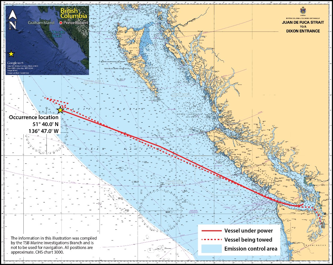
Source of main image: Canadian Hydrographic Service Chart 3000, with TSB annotations
Source of inset image: Google Earth, with TSB annotations
Appendix B – Timeline of major events
| Date | Time | Event |
|---|---|---|
| 30 January 2018 | 1240 | The MOL Prestige departs for Japan. |
| 30 January 2018 | 1940 | Three hours’ notice for fuel changeover is given. |
| 30 January 2018 | 2045 | No. 1 HFO purifiers is started. |
| 30 January 2018 | 2055 | HFO starts being transferred from the settling tank to the service tank via the purifier. |
| 30 January 2018 | 2058 | The high-temperature alarm for the No. 1 HFO purifier sounds. |
| 30 January 2018 | 2110 | Relevant valves to transfer fuel are opened and the HFO transfer pump is started in manual mode. |
| 30 January 2018 | 2115 | A fire alarm sounds on the bridge. White fumes are observed near the settling tank. |
| 30 January 2018 | 2116 | The HFO transfer pump and the No. 1 HFO purifier are stopped. |
| 30 January 2018 | 2117 | The general fire alarm activates. |
| 30 January 2018 | 2118:39 | Burning oil and flames are observed close to the No. 3 generator on deck 4. |
| 30 January 2018 | 2120 | All the crew, with the exception of those in the ER, muster at their designated muster stations. |
| 30 January 2018 | 2130 | The chief officer reaches the ECR with the 2 EEBDs. |
| 30 January 2018 | 2137 | A distress call is sent. |
| 30 January 2018 | 2138 | The chief officer leads 3 crew members out of the engine room; 3 remain in the engine room. |
| 30 January 2018 | 2140 | Boundary cooling behind the superstructure begins. |
| 30 January 2018 | 2223 | The Joint Rescue Coordination Centre in Victoria is alerted about the emergency on the MOL Prestige. |
| 30 January 2018 | 2225 | More fire alarms sound on the vessel. |
| 30 January 2018 | 2240 | The 3 remaining crew use the elevator to exit the engine room. |
| 30 January 2018 | 2243 | The oil tanker Eagle Bay begins proceeding to the MOL Prestige. |
| 30 January 2018 | 2247 | The oil tanker Polar Resolution, which is 75 nm east of the MOL Prestige, is tasked to assist. |
| 30 January 2018 | 2250 | CO2 is released into the engine room. |
| 30 January 2018 | 2255 -2319 | R465 and CCGS Sir Wilfrid Laurier initiate response. |
| 30 January 2018 | 2342 | The master informs MCTS that all crew are accounted for, that the engine room has been flooded with CO2, and that the fire has been extinguished. |
| 01 February 2018 | 0035 -0050 | RCAF search and rescue helicopter 903 (R903) departs Comox, BC, followed by R465. |
| 01 February 2018 | 0120 | The MOL Prestige informs MCTS that the fire is still burning and is not under control, and that the master is reassessing the situation. |
| 01 February 2018 | 0137 | Paint on the outside of door 51 starts blistering and smoke begins coming out from around the door frame. |
| 01 February 2018 | 0137 | 30 cylinders of CO2 are manually released into the engine room. Later, another 54 cylinders are manually released. |
| 01 February 2018 | 0209 | The master informs MCTS that the vessel’s supply of CO2 is low and that smoke is still coming out of the funnel. |
| 01 February 2018 | 0317 | The master informs MCTS that the engine room fire is still burning and that they are unable to access the engine room. |
| 01 February 2018 | 0356 | The Polar Resolution reaches the MOL Prestige and stands by to assist. |
| 01 February 2018 | 0356 | The crew on the MOL Prestige continue with boundary cooling. |
| 01 February 2018 | 0400 | Boundary cooling is stopped momentarily to help the crew assess the situation. The fire appears to be under control. |
| 01 February 2018 | 0907 | MCTS contacts the TSB and reports that there was a fire on the MOL Prestige. |
| 01 February 2018 | 1044 | The master informs MCTS that boundary cooling is ongoing, that smoke is still coming out of the funnel, and that approximately 60 CO2 cylinders are left. |
| 01 February 2018 | 1134 | The Eagle Bay reaches the MOL Prestige and is instructed to remain on site. |
| 01 February 2018 | 1209 | Eagle Bay is told to stand down; the Polar Resolution remains standing by. |
| 01 February 2018 | 1513 | R465 and R903 arrive at the MOL Prestige and evacuate 2 crew. Three other crew are also assessed by search-and-rescue technicians. |
| 01 February 2018 | 1650 | The engine room is checked and found to be still smouldering. |
| 01 February 2018 | Between 1700 and 1715 | The engine room is checked and found to have breathable air and no sign of fire smouldering. |
| 01 February 2018 | 2341 | CCGS Sir Wilfrid Laurier arrives on scene, and the Polar Resolution stands down. |
| 02 February 2018 | Between 1000 and 1215 | The CCGS Sir Wilfrid Laurier provides first aid to three crew members. |
| 03 February 2018 | Between 0930 and 1345 | The engine room and CO2 room are inspected. |
| 03 February 2018 | 1744 | The tug Denise Foss arrives and begins towing the vessel to Seattle, Washington, U.S. |
| 11 February 2018 | 2130 | The tug arrives in Seattle with the MOL Prestige. |
| 20 March 2018 | 1200 | The vessel returns to service after being repaired. |