Main-track train derailment
Canadian Pacific
Train No. 823-957
Mile 41.30, Canadian National Yale Subdivision
Floods, British Columbia
The Transportation Safety Board of Canada (TSB) investigated this occurrence for the purpose of advancing transportation safety. It is not the function of the Board to assign fault or determine civil or criminal liability. This report is not created for use in the context of legal, disciplinary or other proceedings. See Ownership and use of content. Masculine pronouns and position titles may be used to signify all genders to comply with the Canadian Transportation Accident Investigation and Safety Board Act (S.C. 1989, c. 3).
Summary
On 24 October 2004, at 0110 pacific daylight time, Canadian Pacific Railway freight train 823-957, proceeding westward at approximately 37 mph, derailed one car at Mile 41.30 of Canadian National (CN) Yale Subdivision, near Floods, British Columbia. The train proceeded to Mile 44.40 where 23 additional cars derailed. Of the 24 cars derailed, 21 were destroyed and 3 sustained minor damage. Approximately 1500 feet of track, a signal bungalow, and two small out buildings on private property were destroyed, and a level crossing at Mile 42.28 was damaged. No dangerous goods were involved, and there were no injuries.
Ce rapport est également disponible en français.
Factual information
The accident
On 24 October 2004, Canadian Pacific Railway (CPR) westward freight train 823-957 (the train) departed Boston Bar, British Columbia,Footnote 1 destined for Roberts Bank, with two locomotives and 115 bathtub-style gondola cars loaded with coal. The train was 7032 feet long and weighed 15 973 tons. The crew consisted of a conductor and a locomotive engineer. Both crew members were familiar with the route, were qualified for their positions, and met established fitness and rest standards.
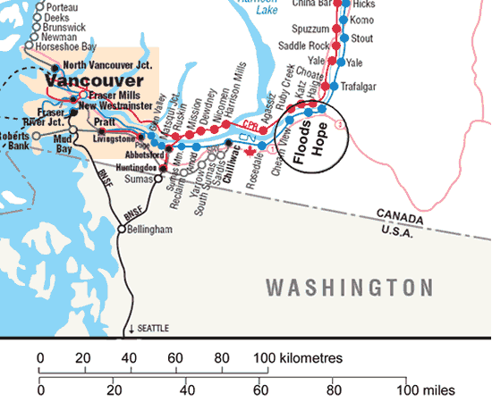
While en route, the train passed over a hot box and dragging equipment site at Mile 39.80 of the Yale Subdivision. There were no indications of dragging equipment. The train experienced an undesired train-initiated emergency brake application at Mile 44.40, which is adjacent to the Trans-Canada Highway (see Figure 1). After coming to a stop, the crew members followed emergency procedures and determined that 24 cars (the 65th through the 88th cars) had derailed. Recorded information indicated that, at the time of the emergency brake application, the train was travelling 37.6 mph with the throttle in idle position.
Site examination
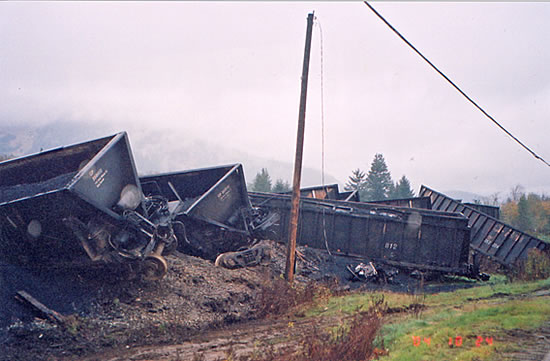
The first derailed car, CP 352170 (the 65th car), derailed the trailing truck, but remained upright and to the north of the main track. The 21 following cars derailed in an accordion pattern over approximately 600 feet, immediately west of the west siding switch at Mile 44.40. The last two derailed cars (the 87th and 88th cars) remained upright, just north of the main track. Approximately 1500 feet of track, a signal bungalow, and two small out buildings on private property were destroyed, and a public crossing at Mile 42.28 was damaged (see Photo 1).
Inspection of the derailed rolling stock revealed that the L-3 axle journal of the fourth derailed car, CP 349499 (the 68th car), had broken and severed immediately behind the roller bearing backing ring in the journal fillet area. The corresponding L and R-3 wheel treads were extensively damaged and displayed fresh nicks and gouges.
Examination of the track structure east of the derailment site revealed intermittent impact marks on the field side of the north rail, as well as damaged ties and tie plates, and track fasteners. The marks extended eastward from the derailment site to Mile 41.30 where the broken axle journal, with its roller bearing still attached, was found at the foot of an embankment on the north side of the track. The failed wheel set and severed axle journal complete with the roller bearing were sent to CPR's Test Department in Winnipeg, Manitoba, for failure analysis.
Track information
The Canadian National (CN) Yale Subdivision extends 113.8 miles from Boston Bar to Thornton Yard, Surrey. Train movements are governed by the Centralized Traffic Control System, in accordance with the Canadian Railway Operating Rules, under the supervision of a CN rail traffic controller located in Edmonton, Alberta. CPR operates some trains over the CN Yale Subdivision. Track in the area of the derailment is single east-west main track with a 6030-foot long siding running adjacent to the south side of the main track. In the derailment area, the maximum authorized speed is 55 mph for passenger trains and 50 mph for freight trains. Six VIA Rail passenger trains per week and approximately 30 freight trains per day travel over this subdivision.
From Mile 41.30 to Mile 42.0 the track structure was comprised of 136-pound continuous welded rail (CWR) on concrete ties, fastened with pandrol clips. From Mile 42.0 westward to the area of the derailment at Mile 44.40, the CWR was laid on double-shouldered tie plates and hardwood ties. The plates were fastened with four spikes per plate and box-anchored at every tie. The ties were in good condition. Ballast throughout the area was approximately 18 inches deep and was composed of pieces about 1 to 1.5 inches in diameter. The shoulders were between 18 and 24 inches wide. No track defects were noted in the derailment area during the most recent visual inspections, track geometry car inspections, or ultrasonic rail testing. The frequency of track inspection and testing was in accordance with current regulations.
Freight car axle information
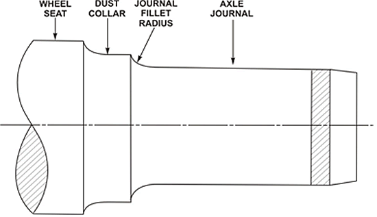
Roller bearings are press-fit onto the journals. Railway wheels are press-fit onto the wheel seats. The journal and wheel seat have different cross-sectional diameters. There are two consecutive radii which transition from the larger diameter wheel seat to the smaller journal. The dust collar extends from the wheel seat to the top of the journal fillet radius; in turn, the journal fillet radius extends from the bottom of the dust collar to the journal surface. Both are supposed to be smooth contoured transitions (see Figure 2).
Transport Canada's Railway Freight Car Inspection and Safety Rules set out minimum safety standards for freight cars. The section concerning axle inspection and safety states that a railway company may not place or continue a car in service if an axle has a crack, or is bent or broken. However, once the wheel set is installed on a freight car truck, the journal fillet radius is concealed by the roller bearing backing ring and, therefore, is not visible during train safety inspections.
When removed from a freight car for any reason, wheel sets are returned to a wheel shop for reconditioning. All wheel set components must be inspected and either scrapped or reconditioned in accordance with the Association of American Railroads (AAR) Manual of Standards and Recommended Practices (MSRP) Section G-II Wheel and Axle Shop Manual (the G-II Manual). Upon arrival at a wheel shop for reconditioning, the wheel tread thickness is measured. If the wheels do not have enough material for re-profiling, the roller bearings and wheels are removed from the axle, and the axle is inspected. If it meets the criteria in the G-II Manual, it is reconditioned before being returned to service.
The axle with the failed journal was a 14-year old Grade F tempered axle manufactured by Standard Forged Products. The axle was fitted with new wheels and reconditioned bearings in February 2004 at Progress Rail's Sidney, Nebraska facility. The subject wheel set was installed in the number three position on car CP 349499 on 08 March 2004. It failed on 24 October 2004. Progress Rail indicated that the subject axle had been reconditioned in accordance with the G-II Manual.
Axle failure analysis
Following the derailment, CPR conducted a failure analysis of the broken axle. This is a summary of CPR findings and TSB observations.
- The axle fractured in the area of the L-3 journal fillet radius, approximately three inches from the outboard face of the wheel hub. The fracture was perpendicular to the axle's longitudinal axis and displayed a fatigue fracture zone and a brittle fracture zone.
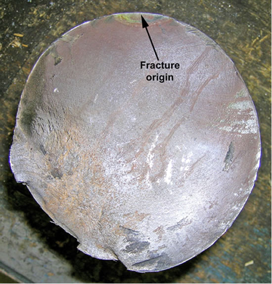
- The fatigue fracture zone was characterized by beach marks. The beach marks were traced back. They indicated that the failure originated from the surface of the L-3 journal fillet radius and progressed in fatigue through approximately 60 per cent of the axle's cross-section (see Photo 2).
- The brittle fracture zone was characterized by a fibrous appearance. It occurred catastrophically under normal service conditions when the load exceeded the strength of the axle's reduced cross-section.
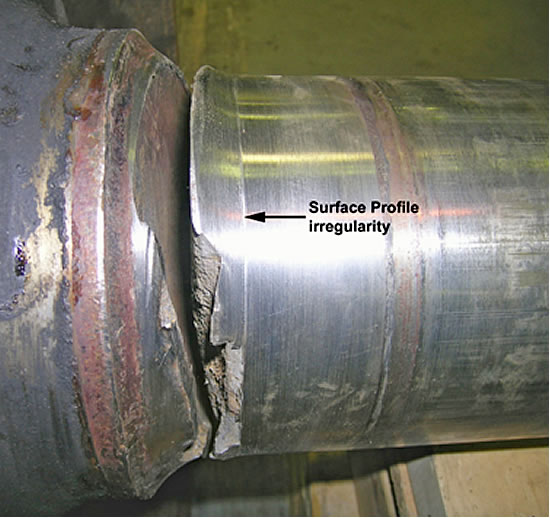
- Visual examination of the axle's two journal fillet radii revealed a profile discrepancy. The failed L-3 journal fillet radius exhibited an abrupt surface profile irregularity at the root of the radius that resulted in an obvious circumferential demarcation (see Photo 3). The R-3 (mate) journal fillet radius exhibited a smooth continuous curve extending from the dust collar to the journal surface.
- The profile irregularity exhibited a slightly angular transition between the journal fillet radius and the journal surface. The root of the angle coincided with the root of the journal fillet radius. The fracture origin corresponded to the root angle of the profile irregularity.
- The axle material conformed to the requirements of AAR Specification M-101 for Grade F steel. The axle steel was free of any deleterious material and/or metallurgical anomalies. Its microstructure consisted of a mixture of fine-grained pearlite and ferrite, which was consistent with the specified material and heat treatment.
The CPR examination of the failed journal fillet radius area determined that it was in compliance with the existing reconditioning standards contained in the G-II Manual.
The G-II Manual
The G-II Manual contains rail industry standards and recommended practices for wheel shop reconditioning and applying wheels and axles. Rule 1 of the G-II Manual contains mandatory rules governing wheel shop practices.
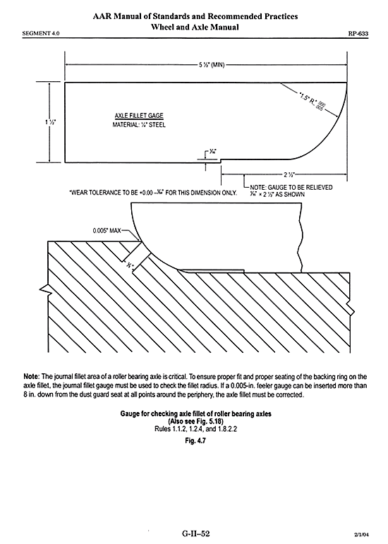
Rule 1.1.2 indicates that second-hand (reconditioned) axles must conform to G-II Manual dimensions and specifications, including those shown in Figure 4.7 of the manual. This figure details the journal fillet gauge that must be used for qualifying the journal fillet radius profiles of reconditioned axles. It also contains a note stating that "the journal fillet area of a roller bearing axle is critical. To ensure proper fit and proper seating of the roller bearing backing ring on the axle fillet, the journal fillet gauge must be used to check the fillet radius." The journal fillet gauge contains a 1/16 inch-deep by 2½ inch-long recess along its base that extends from near the bottom of the journal fillet radius profile, along the journal surface (see Figure 3).
Rule 1.2.4 (in effect at the time the axle was reconditioned) states in, part, that before attempting to qualify axles, the axle ends, journals, journal fillets, dust collar seats, and wear ring grooves must be thoroughly cleaned. The abrasive method may be used provided it is 80 grit or finer. Journal fillet radii with fretting that cannot be removed with abrasive may be refinished by grinding or machine cutting providing the journal dimension is not reduced below the minimum length.
Rule 1.2.5 states, in part, that journals must be carefully inspected for dimensional conformity in accordance with Figure 4.5 each time a roller bearing is removed, to determine if the journal is within prescribed tolerances. Yet Figure 4.5 does not contain any specific reference to the journal fillet radius area. In addition, it states that there shall be no abrupt changes or steps over the length of the journal. Defects shall be smoothly blended (1/8 inch radius or more) into the contour of the journal surface by filing, sanding, or roll burnishing such that there are no high spots and that depressions are no more than 1/16 inch deep.
TSB investigators visited a wheel shop to view journal fillet radius re-profiling on second-hand axles. They observed the machine cutting, sanding, and roll burnishing operations used to blend the root of the journal fillet radius with the journal surface. They concluded that the failed journal fillet radius was slightly undercut and likely not sanded or roll burnished sufficiently to produce a smooth continuous radius contour blending the root of the journal fillet radius with the journal surface.
Analysis
A review of the locomotive event recorder determined that the train was handled in accordance with regulations and company instructions and that train handling was not a factor in this occurrence. Track inspection and testing did not reveal any track defects in the area of the derailment. The analysis will focus on the broken L-3 axle journal of car CP 349499 and on axle reconditioning.
The accident
The train had passed a hot box and dragging equipment site at Mile 39.80. However, because the impending axle failure was located in the journal fillet radius area and because no heat was generated, it could not be detected by the wayside inspection system.
The location of the recovered broken axle journal corresponded to the initial impact marks observed on the track structure and identified the point of derailment at Mile 41.30. Once the journal had severed and broken free of the truck side frame, the unsupported truck side frame dropped to the surface of the track structure. The truck side frame was dragged along the surface until it struck a main-track switch at Mile 44.40, resulting in the derailment of an additional 23 cars.
The journal area of the axle is the primary weight bearing area. Essentially, the weight of a freight car is placed on a roller bearing and transferred to the wheel through the journal fillet radius. As a result, the journal fillet radius is subject to high loading and flexing during normal service with the highest loading occurring at the root of the journal fillet radius as it transitions to the reduced cross-section of the journal surface. Consequently, this area becomes more notch sensitive, and surface imperfections within the area act as stress raisers.
Failure analysis identified that the fatigue fracture origin corresponded to a circumferential surface profile irregularity located at the root of the journal fillet radius. The observed surface profile irregularity was likely introduced during axle reconditioning, yet the axle met the current AAR standard. The profile irregularity resulted in a slightly angular transition between the journal fillet radius and the journal surface with the root of the angle coinciding with the root of the journal fillet radius. With this profile, the surface irregularity became a nucleation point for service stresses at the root, acted as a stress raiser, and facilitated the initiation of the fatigue fracture. Once initiated, a fatigue fracture progressed through 60 per cent of the journal cross-section. Final catastrophic failure occurred under normal service conditions when the load exceeded the diminished strength of the journal's reduced cross-section.
Axle reconditioning
The failed axle material met AAR manufacturing specifications. Progress Rail identified that the axle had been reconditioned in accordance with shop practices outlined in the G-II Manual. CPR indicated that the profile of the journal fillet radius on the failed axle journal met the requirements of the standard. However, the journal failed after only six months of service, and the fracture originated from a profile irregularity at the root of the journal fillet radius, likely introduced when the axle was reconditioned. This raises the issue of the adequacy of the current AAR axle reconditioning standard.
Rule 1.1.2 of the G-II Manual indicates that reconditioned axles must conform to the manual's dimensions and specifications. It notes that a journal fillet gauge must be used to check the profile of the journal fillet radius to ensure proper fit and seating of the roller bearing backing ring on the journal fillet radius. However, the journal fillet gauge, used to check radius profiles, contains a 1/16-inch deep by 2½-inch long recess along its base that does not come into contact with the root of the journal fillet radius (see Figure 3). Consequently, as demonstrated by this occurrence, it is possible for a profile with an irregularity, such as a slightly angular transition at the root of the journal fillet radius, to appear to conform to the gauge profile. Therefore, the journal fillet gauge does not provide for adequate inspection for compliance-to-profile at the root of the journal fillet radius.
In addition, elements of Rule 1.2.5 are not specific and remain unclear. For example, the rule also states that journals must be carefully inspected for dimensional conformity in accordance with Figure 4.5 each time a roller bearing is removed, to determine if the journal is within prescribed tolerances. Yet Figure 4.5 does not contain any specific reference to the area of the journal fillet radius. The rule states that there shall be no abrupt changes or steps over the length of the journal, but does not define the limits of an abrupt change or step. The rule also requires that surface defects be blended smoothly into the contour of the journal surface (which includes the journal fillet radius) with a radius of 1/8 inch or greater, such that there are no high spots and that depressions are no more than 1/16 inch deep. Therefore, this implies that depressions less than 1/16 inch, such as the profile irregularity observed in this occurrence, are permitted. When Rule 1.2.5 is considered in conjunction with the shortcoming of the current journal fillet gauge, the current standard may permit axles with journal fillet radius profile irregularities, located at the root of the fillet, to return to service with a commensurate risk of premature journal failure.
Findings
Findings as to causes and contributing factors
- The L-3 axle journal of car CP 349499 failed at Mile 41.30. Once the broken journal had separated, the unsupported truck side frame dropped to the ground and was dragged until it struck a main-track switch at Mile 44.40 resulting in the derailment of an additional 23 cars.
- A fatigue fracture originated at a circumferential surface profile irregularity located at the root of the L-3 journal fillet radius and progressed through 60 per cent of the journal cross-section. Final failure occurred catastrophically, under normal service conditions, when the load exceeded the diminished strength of the journal's reduced cross-section.
- The surface profile irregularity was likely introduced during axle reconditioning, even though the reconditioned axle met the current Association of American Railroads (AAR) standard. The surface profile irregularity became a nucleation point for service stresses at the root of the journal fillet radius, acted as a stress raiser, and facilitated the initiation of the fatigue fracture.
Findings related to risk
- The journal fillet gauge, used to check radius profiles (see Figure 3) is not adequate to ensure that the root of the journal fillet radius complies with the required radius profile.
- When Rule 1.2.5 of the AAR Manual of Standards and Recommended Practices (MSRP) Section G-II Wheel and Axle Shop Manual is considered in conjunction with the shortcoming of the journal fillet gauge, the current standard may permit reconditioned axles with journal fillet radius profile irregularities, located at the root of the journal fillet, to return to service with a commensurate risk of premature journal failure.
This report concludes the Transportation Safety Board's investigation into this occurrence. Consequently, the Board authorized the release of this report on .
