Main-track train derailment
Canadian National Railway Company
Freight train U70451-02
Mile 88.75, Ruel Subdivision
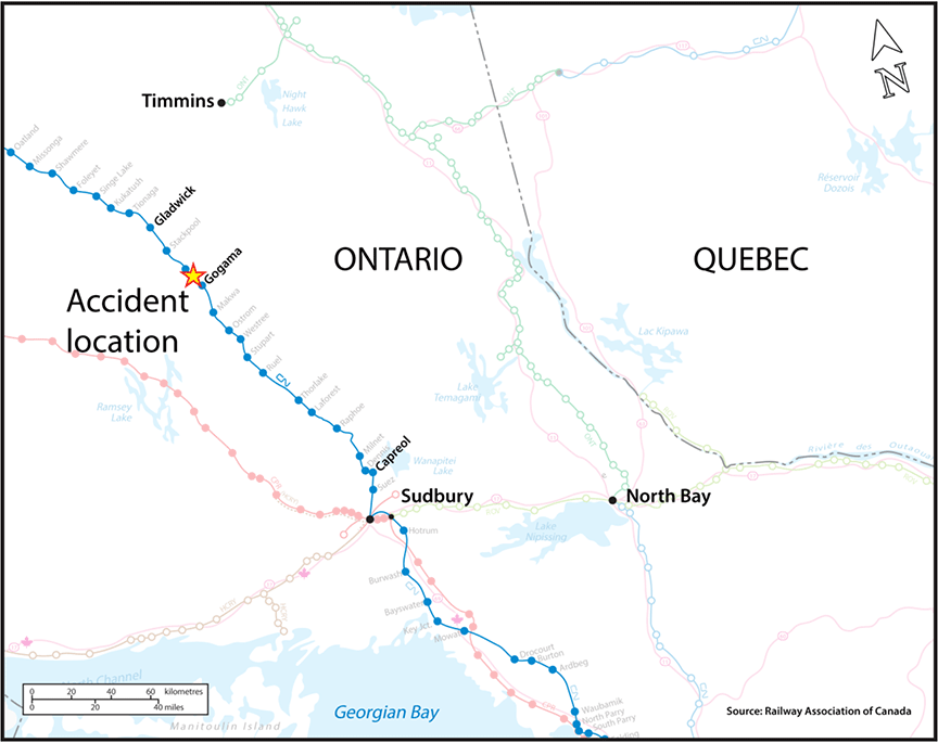
Gogama, Ontario
The Transportation Safety Board of Canada (TSB) investigated this occurrence for the purpose of advancing transportation safety. It is not the function of the Board to assign fault or determine civil or criminal liability. This report is not created for use in the context of legal, disciplinary or other proceedings. See Ownership and use of content. Masculine pronouns and position titles may be used to signify all genders to comply with the Canadian Transportation Accident Investigation and Safety Board Act (S.C. 1989, c. 3).
Summary
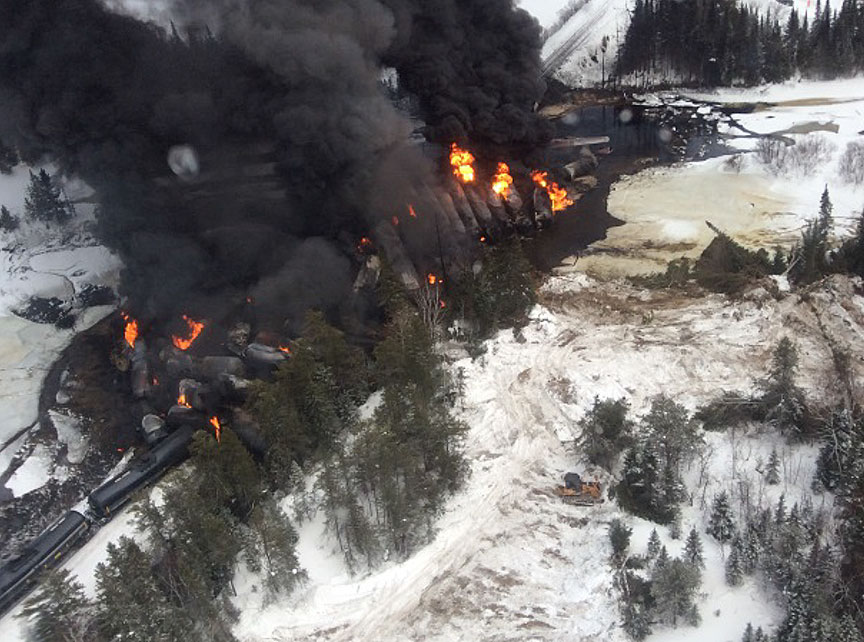
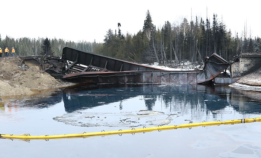
On 07 March 2015, at 0242 Eastern Standard Time, Canadian National Railway Company (CN) crude oil unit train U70451-02 was proceeding eastward at about 43 mph on CN's Ruel Subdivision when it experienced a train-initiated emergency brake application at Mile 88.70, near Gogama, Ontario. A subsequent inspection determined that the 6th to the 44th cars (39 cars in total) had derailed. As a result of the derailment, about 2.6 million litres of petroleum crude oil (UN1267) was released to atmosphere, water, or surface. The released product ignited and caused explosions, and some product entered the nearby Makami River. A CN bridge over the Makami River (at Mile 88.70) and about 1000 feet of track were destroyed. There was no evacuation, and there were no injuries.
Le présent rapport est également disponible en français.
1.0 Factual information
On 02 March 2015, Canadian National Railway Company (CN) crude oil unit train U70451-02 (the train) departed eastward from Redwater, Alberta, destined for the Valero Energy Incorporated (Valero) refinery located at Lévis, Quebec. The train consisted of 2 head-end locomotives and 94 tank cars loaded with petroleum crude oil (UN1267). It weighed 13 497 tons and was 5733 feet long. The train was designated as a key trainFootnote 1 operating on a key route.Footnote 2
On 06 March 2015, a regular crew change was made at Hornepayne, Ontario, located at Mile 296.2 of CN's Ruel Subdivision.Footnote 3 The outbound train crew consisted of a locomotive engineer, a trainee, and a conductor. All crew members met fitness and rest standards and were qualified for their respective positions. The train departed eastward on the subdivision at about 2230.Footnote 4
The Makami River flows southward towards the town of Gogama, Ontario (Mile 86.60), and into Minisinakwa Lake. The river then flows around Gogama, turns northeast and flows towards Timmins and the Mattagami First Nation. A CN mainline rail bridge spans the river at Mile 88.70.
1.1 The accident
At about 0242 on 07 March 2015, while the train was proceeding at about 43 mph, the locomotive forward- facing video recorded a slight dip just before a train-initiated emergency brake application occurred at Mile 88.70 near Gogama (Figure 1). The train crew looked back and observed a large explosion and ensuing fire. They followed the emergency procedures and made the necessary radio broadcast. After the train came to rest, the crew inspected the train and determined that tank cars behind the 5th car from the head end had derailed and were on fire. The crew disconnected the locomotives and the first 5 cars from the train and travelled to a safe location east of the fire. There were no injuries and there was no evacuation.
Just west of the derailment area, the tail end of the train was blocking the crossing at Highway 144 (Mile 88.98). The crossing was subsequently cleared when the tail end of the train was pulled westward by locomotives from eastbound CN train 112, and the tank cars were left at Stackpool, Ontario (Mile 105.4).
The temperature at the time of accident was −9 °C, and there was an 11 km/h wind from the northwest. For the 7 days following the derailment, the weather was similar and close to seasonal norms.
1.2 Site examination
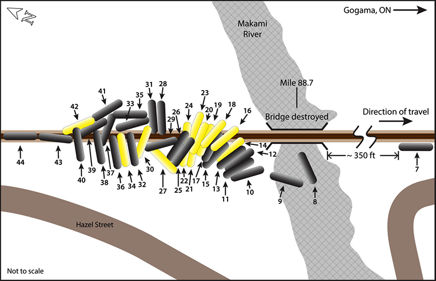
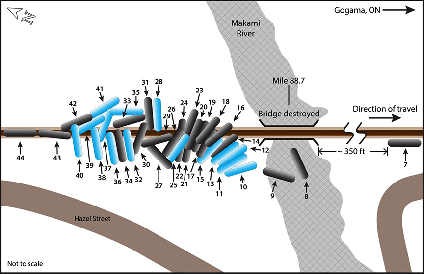
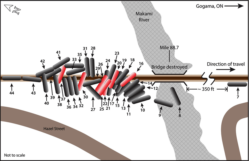
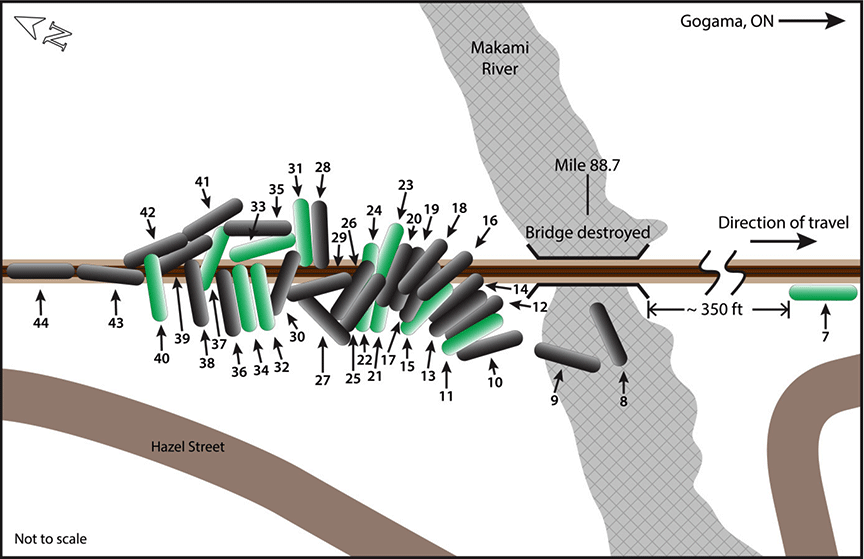
The 6th to the 44th cars from the head end (39 tank cars) had derailed (Figure 2). The 6th car (VMSX 310431) had travelled across the rail bridge over the river and derailed upright to the south of the track. The 6th car was subsequently re-railed and removed from the site. The trailing end of the 7th car (VMSX 310442) had struck the south side of the bridge structure and rolled down the south side embankment about 350 feet east of the bridge. Its bottom outlet valve was damaged and product was released. The 8th car (VMSX 311916) struck the bridge heavily and came to rest in the river south of the bridge, along with parts from 5 other cars. Most of the remaining derailed cars had jackknifed on the west approach to the bridge and travelled down the south embankment. The last two derailed cars, the 43rd and 44th cars (VMSX 310060 and VMSX 311681), derailed upright and came to rest near Mile 88.75.

Of the 39 derailed tank cars, 33 had been breached and released product, fuelling the fire, and some product entered the river. The fire occupied an area about 300 yards in diameter and was centred near the west end of the rail bridge (Figure 3). The bridge and about 1000 feet of track were destroyed (Figure 4).
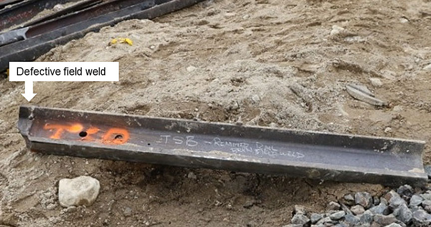
Approaching the derailment site from the west, there were no impact marks observed on the track infrastructure. At the west end of the derailment site, a number of broken pieces of the south rail were observed in the vicinity of Mile 88.75, as follows:
- Sitting beside the track were 2 sections of rail, one measuring 68 inches long and one measuring 78 inches long, which contained a defective field weld (DWF) that had been removed from the south rail 3 days before the accident, during the repair of a broken rail (Figure 5).
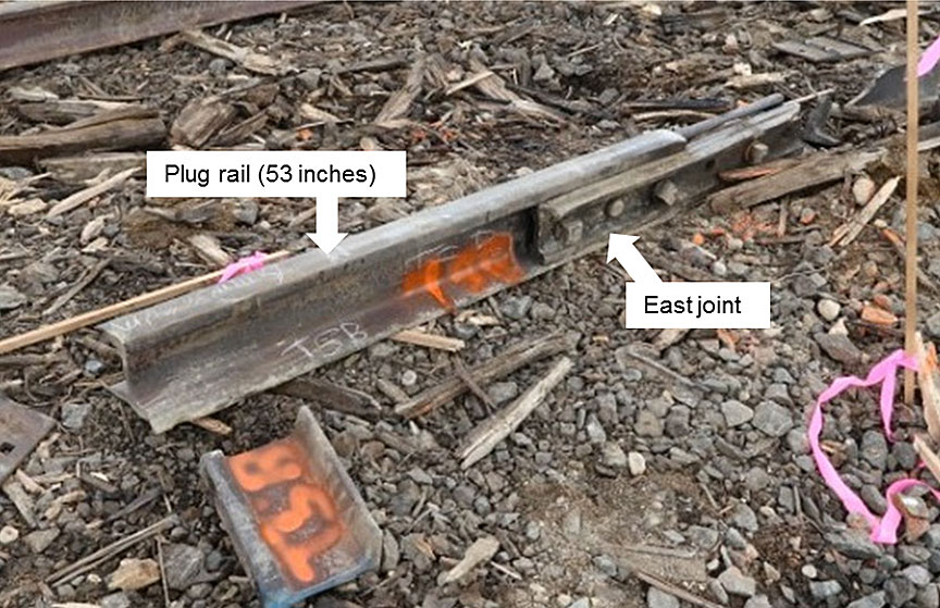
- The east joint of the plug rail, with joint bars still holding together an intact 53-inch-long section of plug rail and a fractured 20-inch-long section of parent south rail, was recovered about 265 feet west of the west bridge abutment (Figure 6).
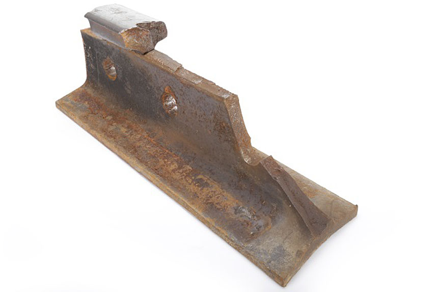
- Most of the rail head of the 20-inch section had broken off (Figure 7). Only a 4-inch-long piece of the rail head was recovered.
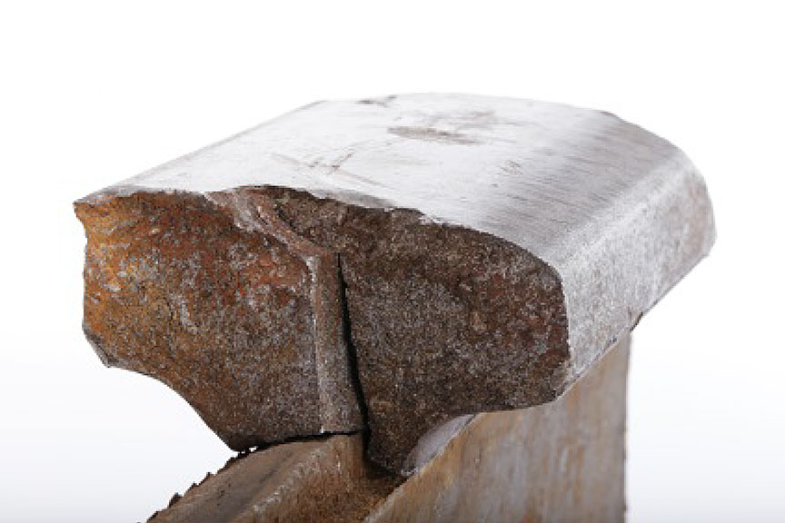
- The 4-inch-long piece of the rail head that was recovered exhibited a vertical split head (VSH) rail defect (Figure 8).
- The west joint of the plug rail connected 28 inches of plug rail and 72 inches of parent rail.
The recovered rail components were sent to the TSB Engineering Laboratory for analysis.
During site cleanup, the first derailed car was re-railed and taken to Capreol, Ontario (Mile 0.0), on the Ruel Subdivision. The 7th to 43rd cars were destroyed. The 44th car was re-railed and sent to destination at Lévis, Quebec, on 13 March 2015.
1.3 Locomotive video recorder
The lead locomotive, CN2913, was equipped with a forward-facing camera that provided a video and audio recording with date, time, and speed information. Based on the camera's recording, it was determined that an impact sound and a vibration in the locomotive cab occurred 4 seconds before the train encountered the west end of the bridge. Three seconds later, a train-initiated emergency brake application occurred.
1.4 Dangerous goods
The transportation of dangerous goods (DGs)Footnote 5 is governed by federal regulations in CanadaFootnote 6 and in the United States.Footnote 7 These regulations are based on the United Nations Recommendations on the Transport of Dangerous Goods.
In this occurrence, petroleum crude oil (UN1267) was being transported in each tank car. The product was listed as Class 3 flammable liquid, Packing Group (PG) I, which is the most hazardous group in this class.
1.4.1 Class 3 flammable liquids
Class 3 flammable liquids are DGs whose vapours can form an ignitable mixture with air at or below a temperature of 60 °C. These flammable liquids can pose serious hazards due to their volatility and flammability, which are determined by the initial boiling pointFootnote 8 and the flash point, respectively.Footnote 9
Because the volatility and flammability vary widely, products in this class are grouped together based on these characteristics so that different requirements, including packaging, storage, handling, and transportation, can be established. According to the Transportation of Dangerous Goods Regulations, Class 3 flammable liquids are divided into 3 packing groups, ranging from PG I (highest hazard) to PG III (lowest hazard). The specific criteria for these packing groups are:
- PG I, if the flammable liquid has an initial boiling point of 35 °C or less at an absolute pressure of 101.3 kPa and any flash point.
- PG II, if the flammable liquid has an initial boiling point greater than 35 °C at an absolute pressure of 101.3 kPa and a flash point less than 23 °C.
- PG III, if the criteria for inclusion in PG I or PG II are not met.
1.4.2 Petroleum crude oil
Petroleum crude oil has a wide range of flammability and volatility characteristics. The product is usually qualified in terms of sulphur content (low sulphur being "sweet" and high sulphur being "sour") and density (light to heavy). The density of petroleum crude oil is described in terms of its American Petroleum Institute (API) gravityFootnote 10 (expressed in degrees), where a higher number indicates lower density. The thresholds defining "light," "medium," and "heavy" crude oil vary depending on the product's region of origin and the organization making the determination.Footnote 11
Petroleum crude oil can also vary in viscosity, which is often referred to as the thickness of a fluid. Products with low viscosity (e.g., water) flow freely, while products with high viscosity (e.g., molasses) are thicker and do not flow freely.
1.4.3 Emergency response procedures for petroleum crude oil
Guide 128 of the Emergency Response Guidebook.Footnote 12 identifies the potential hazards of petroleum crude oil products, including petroleum distillates. Guidance is provided for emergency response and for ensuring public safety.
Under the heading "Potential Hazards,"Footnote 13 the guide indicates:
- These products are lighter than water, are highly flammable, and will be easily ignited by heat, sparks or flames.
- The product vapours are heavier than air; they will spread along the ground and collect in low or confined areas (e.g., sewers, basements, or tanks). These vapours may form explosive mixtures with air, and may travel to source of ignition and flash back.
- These products are associated with a vapour explosion hazard indoors, outdoors or in sewers, and containers may explode when heated.
Under the headings "Emergency Response"Footnote 14 and "Public Safety,"Footnote 15 the guide states that
- Water spray, fog or regular foam should be used to fight fire, but not straight streams of water. Because these products have a very low flash point, water spray may be inefficient; it may be necessary to use vapour-suppressing foam to reduce vapours.
- An initial downwind evacuation for at least 300 metres (1000 feet) should be considered.
- All ignition sources must be eliminated.
- All equipment used when handling the product must be grounded.
- Responders must not touch or walk through spilled material.
- The leak should be stopped if it can be done without risk.
- Entry into waterways, sewers, basements or confined areas should be prevented.
- Spilled product should be absorbed or covered with dry earth, sand or other non-combustible material, and transferred to containers.
- Clean, non-sparking tools should be used to collect absorbed material.
1.5 Emergency response
The accident occurred about 2 miles west of the town of Gogama and 0.25 miles east of Highway 144. There was good access to the site, which facilitated mitigation activities.
CN and the Gogama fire service immediately implemented a unified incident command system. With cooperation from the local municipality, the Gogama town hall, located approximately 2 miles northeast of the derailment site, was established as the incident command center (ICC). The ICC served as the location for internal and external responders to provide updates on remediation plans, site mitigation progress, operational recovery plans, and other safety concerns.
CN's remediation plans were shared with all responders and local stakeholders at regular pre-planned times. Other response agencies established work centres within the ICC to coordinate activities. The ICC also provided relief to responders from the weather, and hot meals were available to responders and support personnel around the clock.
Sign-in and sign-out control procedures for all response personnel were established and monitored 24 hours a day from the ICC. CN police and security personnel controlled derailment access at checkpoints surrounding the perimeter of the site.
All responders who required access to the site were issued either a half- or a full-face respirator complete with supporting "fit test" documentation and proper filter canisters. CN dangerous goods officers performed regular air testing throughout the derailment site, monitoring for hydrogen sulfide (H2S) and hydrocarbon explosive level thresholds. Drager tube testing for airborne benzene was conducted at half-hour intervals. Wind socks were erected at strategic locations to provide responders with advance warning when changing wind conditions increased the potential risk of inhalation hazards.
Water samples and water testing results from nearby Minisinakwa Lake and its tributaries were on display in the ICC as derailment mitigation and environmental remediation progressed. Photographs and topographical maps were posted, regularly updated, and consistently made available to residents and the general public. Ongoing environmental impact assessments were conducted and discussed among all stakeholders. Future remediation commitments were shared with the local community.
CN mobile command posts were positioned at the east end and the west end of the site perimeter. Each command post was equipped with food, water, first aid equipment, and replacement safety equipment for distribution to personnel as necessary, and was used to provide relief to responders from the weather. Secondary job briefings and directions regarding remediation plans were also coordinated and communicated from these mobile command posts.
A detailed information session involving provincial and municipal officials, First Nations Chiefs and elders, response agencies, and Gogama residents, was chaired by CN 4 days into the derailment cleanup. A follow-up town hall meeting took place in Gogama in November 2015 to reassure the stakeholders of CN's continued involvement with the environmental cleanup.
1.6 Track restoration and bridge replacement
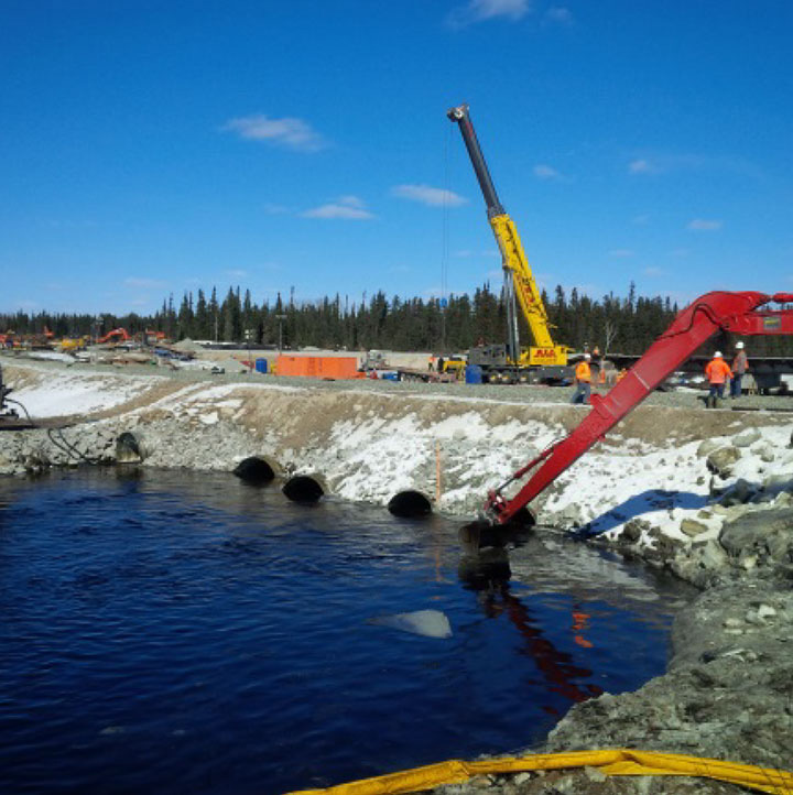
Because the accident resulted in a lengthy track outage and impacted rail operations, CN constructed a 1482-foot-long diversion track to the south of the accident site (Figure 9).
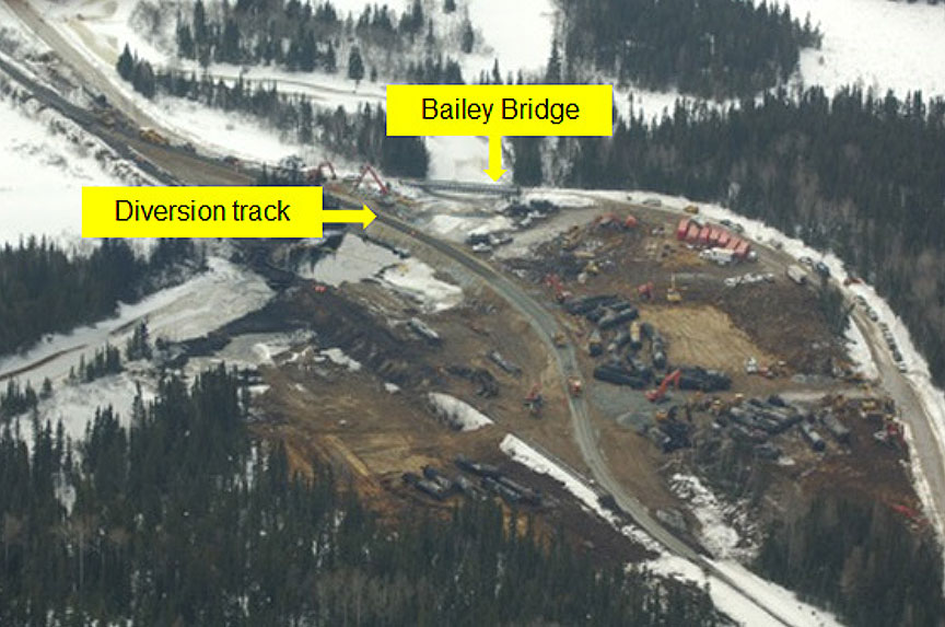
The diversion bridged the Makami River with 5 culverts (Figure 10) and was in service from 10 March to 18 March. About 130 trains were routed over the diversion track during that period.
The destroyed bridge was replaced with 2 previously used beam spans, each measuring 49 feet long, and a steel tray ballast deck. The replacement bridge was supported on the existing bridge abutments. A new centre pier was built out of 4 steel casings filled with concrete and a new precast concrete cap. The first train went over the new bridge on 18 March 2015. Once the new bridge (Figure 11) was operational, the diversion track over the Makami River was removed and the riverbed restored.

1.7 Environmental impact
1.7.1 Site description
Along the north shore of the river, there is a low-lying wetland area. Along the south shore of the river, there is a low-lying wetland area and an upland dense forested area.
Old Gogama Road (also known as Hazel Street) is located south of the track and generally runs parallel to the mainline track and the river. Old Gogama Road crosses the river at the Bailey Bridge, located about 250 m downstream (south) of the mainline rail bridge.
The majority of the tank cars derailed along the north shore of the river just east and west of the north abutment of the rail bridge. Two tank cars came to rest in the river. Initially, there was visual evidence of released product in the river and along the north shore, east and west of the mainline.
Of the more than 4 million litres of petroleum crude oil transported in the derailed cars, approximately
- 1.6 million litres of product burned to atmosphere;
- 1 million litres of product was lost to surface or water; and
- 1.4 million litres of product was recovered and transferred from the tank cars.
1.7.2 Surface water monitoring program
Following the initial site containment and booming strategies, a surface water sampling program was initiated within the river and Minisinakwa Lake. A total of 14 sample stations were established upstream of the derailment site and downstream of the river extending into Minisinakwa Lake. Samples were collected daily for several weeks until the test results stabilized. Sampling frequency was reduced to twice weekly following several consecutive rounds of sampling which showed no detection of petroleum products, as verified with the Ontario Ministry of the Environment and Climate Change and Environment and Climate Change Canada. Reduced sampling continued along and within the river until November 2015. During the winter, the sites were inspected on a monthly basis as part of monthly groundwater sampling and product collection events. Surface water monitoring resumed in the spring of 2016 and was expected to continue on a quarterly basis for an indefinite period.
Despite these efforts, a thin sheen of oil on the river surface and some dead fish were reported by concerned citizens during the summer of 2016. CN followed up on these concerns and continued to sample and test the soil, sediment, and water in the areas identified. Tests were also conducted on some of the dead fish. Initially, an independent review determined that the test results met regulatory standards, and the results were shared with community leaders. However, at the time that this TSB investigation report was released, Environment and Climate Change Canada was continuing to investigate alleged violations of the pollution prevention provisions of the Fisheries Act.related to this accident.
1.7.3 Wastewater treatment
A water treatment plan was initiated to treat all recovered impacted water. A mobile wastewater treatment unit (MTU) was sent to the accident site. However, after several attempts to treat the impacted water, it was determined that on-site treatment would not be possible due to the levels of petroleum hydrocarbons present in the water. Arrangements were made with an off-site disposal facility operated by Clean Harbours in Sarnia, Ontario, which was approved by the province to accept the impacted oily water.
The oil/water mixture collected at the site was stored in temporary fixed-axle storage tanks (frac tanks). Several of the frac tanks were set up with a series of baffles that helped concentrate the oil as much as possible. The concentrated oil was removed from the tops of the frac tanks and packaged in dedicated frac tanks as a separate waste stream. The concentrated oil was sampled and analyzed for potential recycling or reuse. The remaining oily water and emulsion was shipped by tank truck for off-site disposal. The water was separated and treated. When it was determined that the water met regulatory requirements, it was discharged back into the natural environment.
Although the most significant wastewater treatment activities had been completed, a small amount of oil remained in the ecosystem, as confirmed by water tests taken throughout the cleanup process. However, independent test results showed that water quality in the ground, river, and lake met regulatory standards.
1.7.4 Groundwater monitoring
A total of 19 groundwater monitoring wells were installed to verify the direction of groundwater flow and depth, and to determine whether groundwater had been impacted. The wells were installed around the site perimeter, which included both sides of the CN right-of-way within the CN property limits and on Crown land.
Petroleum was detected in 3 wells located along the containment area and the CN right-of-way property boundary. Following remediation of the containment area, the detected concentration of petroleum at these 3 wells decreased to the point where it was considered to be of minor residual impact rather than a leak within the containment system.
As of June 2017, 2 of the wells located on Crown land exceeded provincial standards for hydrocarbons, and monitoring was ongoing.
In September 2016, an additional 10 monitoring wells were installed along the west bank of the Makami River. As of June 2017, one of the 10 new wells exceeded provincial criteria for toluene and petroleum hydrocarbons, and ongoing monitoring was required.
1.7.5 Sediment dredging
Sediment dredging from the riverbed was completed under the approval of the Ontario Ministry of Natural Resources and Forestry, the Ontario Ministry of the Environment and Climate Change, and Fisheries and Oceans Canada. The dredging consisted of vacuum removal of sediment within a section of the river, beginning upstream of the CN rail bridge and continuing downstream to the Bailey roadway bridge. The start and end points of the sediment removal were determined by an ecological risk assessment that included the collection and analysis of sediment samples taken throughout the entire river. The depth of sediment removal ranged from 15 cm to 30 cm, depending on the topography of the riverbed. Impacted sediment was removed and disposed of at a licensed facility.
Water effluent from the sediment dredging was treated using an on-site MTU. The MTU, which was provincially governed and approved, was operated under a mobile Certificate of Approval or Environmental Compliance Approval that contained sampling requirements and discharge criteria. The criteria were strictly adhered to before any treated water was discharged back to the natural environment. In October 2015, water treatment was terminated after the sediment dredging operations were completed.
In 2016, local residents continued to report the presence of oil sheens on the river surface when sediment was disturbed. In response, CN re-established a consultation panel of experts in the fall of 2016. The panel included representatives from Environment and Climate Change Canada, Fisheries and Oceans Canada, the Ontario Ministry of Natural Resources and Forestry, the Ontario Ministry of the Environment and Climate Change, the Gogama Local Services Board, and the Mattagami First Nation, as well as subject-matter experts in sediment remediation.
It was subsequently agreed by all parties that additional riverbed dredging operations were to be conducted within the area of the rail bridge and in 2 areas just south of Bailey Bridge. The riverbed in each of the 3 areas was vacuumed, dredged, and cleared of sediment. To help the sediment re-establish continuity and create new fish spawning areas, the riverbed was then restored by placing a layer of clean pit stone (cobble and boulder-sized) which was covered with pea gravel. The elevations and amount of material added were assessed on a case-by-case basis, based on pre-dredge elevations and the volume of material removed. Sampling of the river and derailment site is to resume in the spring of 2017.
1.7.6 Shoreline cleanup
Two shoreline cleanup assessment techniques (SCAT) were completed to address the potential impacts to the river and lake shorelines. The SCAT teams included representatives from Environment Canada, the Mattagami First Nation, the Gogama local services board, and several SCAT-certified technicians. Visual and physical inspection of the shorelines, accessible surface water, and associated vegetation were conducted on the entire river downstream of the derailment as well as the north, south, and island shorelines of Minisinakwa Lake. Both assessments were documented in a full SCAT report.
The first SCAT assessment identified 4 areas along the river as well as locations on the north shore of Minisinakwa Lake and the main island that had signs of oil deposit or staining. The second SCAT assessment identified relatively small areas of wetland and upland grasses within the river that showed staining. SCAT crews subsequently cut and removed all impacted vegetation.
1.7.7 Soil excavation and containment
There was a significant volume of impacted soil adjacent to the north rail bridge abutment. This area contained natural low-lying wetlands where pike had historically spawned. Because these areas were prone to seasonal flooding and high spring water levels, it was imperative to excavate the impacted soils as soon as possible to minimize damage to the fish stock and eliminate the potential for impacted soils to be washed from the site and downstream into the river.
A total of 8 lined soil containment cells were constructed to store contaminated soil until it could be transported to an approved landfill site. Impacted soil was loaded into the cells and stored while soil excavation and sample testing was completed. Each cell could contain about 2500 m³ (5000 tonnes) of soil. The cells were tarped to prevent precipitation from entering the contaminated soil. A total of about 37 500 m³ of contaminated soil was shipped by truck to an approved landfill in Cartier, Ontario.
1.7.8 Product recovery from CN right-of-way
A non-permeable liner and sheet pile wall were installed along the east and west sides of CN's right-of-way property boundary. The liner and sheet pile were tied into a concrete cut-off wall that was connected to the bridge abutment. This arrangement created a containment basin for any remaining product that might seep out of the ballast. Each month, any remaining product was removed and disposed off-site at a certified facility.
1.7.8 Site restoration
CN submitted a detailed restoration plan to the regulatory agencies and to the Mattagami First Nation for consideration and comment. Site restoration, which included a diverse planting program to return the lost vegetation species that were native to the area, was completed with the assistance of the local Mattagami First Nation in the fall of 2016. Shoreline restoration was completed in the fall of 2016. A fish spawning lagoon was created in the vicinity of the bridge.
CN prepared a remediation report, which was made available to the regulators and the Mattagami First Nation. A follow-up report was to be prepared to document the restoration work and any additional remedial work required to complete site restoration. Following each sampling program, a summary report was prepared and submitted to the Ontario Ministry of the Environment and Climate Change. These summary reports were to continue until it was determined that no further monitoring or remedial action was required. Normally, site restoration is not considered complete until approval for site closure is received from the Ontario Ministry of the Environment and Climate Change.
1.8 Track and subdivision information
All railway lines are defined as a particular class of track that is related to the condition or maintenance level of the track. The Transport Canada (TC)–approved Rules Respecting Track Safety, also known as the Track Safety Rules.(TSR), outline classes of track and the associated maximum permitted train speeds for each class. Under the TSR, the lowest class of track is Class 1, which restricts freight train speed to a maximum of 10 mph, and the highest class of track is Class 5, which has a maximum permitted freight train speed of 80 mph.
CN's Ruel Subdivision consists of a single main track that extends westward from Capreol, Ontario (Mile 0.0) to Hornepayne, Ontario (Mile 296.2). Train movements on the subdivision are governed by centralized traffic control (CTC), as authorized by the Canadian Rail Operating Rules.(CROR), and supervised by a rail traffic controller (RTC) located in Toronto, Ontario.
In the vicinity of the derailment, the track is Class 4. The authorized track speed is 50 mph for freight trains and 55 mph for passenger trains. Traffic on the Ruel Subdivision consisted of an average of 18 freight trains per day. A VIA Rail Inc. passenger train operated westbound on Wednesdays and Sundays, and eastbound on Wednesdays and Fridays.
The track throughout the derailment area is tangent single mainline generally oriented in an east-west direction. It consists of 136-pound continuous welded rail (CWR) manufactured by Sydney in 1993. Rail wear was measured at 8 mm, which was less than 75% of the vertical condemning limit. The rail was laid on 14-inch double shoulder tie plates supported by No. 1 hardwood ties spaced at 20-inch centres, secured with 5 spikes per plate, and box-anchored every second tie. The ties were in fair condition. The ballast was clean crushed rock. The shoulders were about 12 inches wide, the cribs were full, and the drainage was good.
The Makami rail bridge was a 99-foot-long single span, open-deck, thru-plate girder bridge built in 1910. The bridge had 115-pound guard rails spiked to the bridge timbers with transition ties on both ends. It was inspected annually. The last inspection had been conducted on 17 September 2014, with no defects recorded.
Between 2010 and 2014, rail freight traffic on the Ruel Subdivision had increased from 32.8 million gross ton miles per mile (MGTM/M) to 47.1 MGTM/M (Table 1). During the same period, the number of car loads of petroleum crude oil had increased from 62 to 75 186.
| Year | Freight (MGTM/M)* |
Freight GTM (thousand) |
Crude oil GTM (thousand) |
Crude oil (carloads) |
Crude oil (MGTM/M) |
|---|---|---|---|---|---|
| 2010 | 32.8 | 9 709 654 | 2 263 | 62 | 0.007 |
| 2011 | 35.3 | 10 452 629 | 71 369 | 2 843 | 0.240 |
| 2012 | 36.8 | 10 897 795 | 459 077 | 19 399 | 1.549 |
| 2013 | 37.2 | 11 013 838 | 835 271 | 34 384 | 2.819 |
| 2014 | 47.1 | 13 956 400 | 1 937 152 | 75 186 | 6.540 |
* The terms million gross tons (MGT), gross ton miles (GTM), MGTM, and MGTM/M are used interchangeably in the rail industry.
1.9 Track inspection
For federally regulated track, the minimum regulatory requirements for track inspection are set out in the TSR. Where track is identified as not meeting the track safety rules, the railway company must immediately bring the track into compliance or halt operations over that track.Footnote 16
1.9.1 Visual inspection
The TSR require Class 4 track to be visually inspected twice a week. During the winter of 2015, CN instituted a requirement for daily track inspections in the Northern Ontario Zone because of temperature, snow, and track conditions. The track was visually inspected by an assistant track supervisor (ATS) on 04 March 2015. No defects were noted in the area of the joint.
1.9.2 Track geometry inspection
According to the TSR, for Class 4 track with more than 35 MGT of annual traffic, a track geometry inspection must be performed with a heavy geometry inspection vehicle at least 2 times a year.
On the Ruel Subdivision, CN conducted track geometry testing 4 to 6 times per year.Footnote 17 The most recent track geometry car inspection had been completed on 02 November 2014, about 3 months prior to the derailment. No defects were detected within a mile of the derailment location.
Table 2 provides a summary of CN priority, near-urgent, and urgent geometry defects on the Ruel Subdivision from 2011 to 2014.
| Defect type | 2011 | 2012 | 2013 | 2014 |
|---|---|---|---|---|
| Priority | 14 538 | 30 634 | 13 827 | 9 053 |
| Near-urgent | 5 030 | 11 971 | 5 326 | 2 289 |
| Urgent | 390 | 892 | 308 | 302 |
| Total | 19 958 | 43 497 | 19 461 | 11 644 |
CN Engineering Track Standards.(ETS), track standard (TS) 7.1, "Track Geometry," specifies (in part) that
- Deviations exceeding Transport Canada Track Safety Rules……for track geometry are defined as "URGENT" defects.Footnote 18
TS 7.1 further indicates that
- Where a portion of the track exceeds the limits defined as "URGENT", one of the following actions must be immediately taken before the operation of the next train over the defect(s):
- the defect must be repaired to within the allowable tolerances;
- […]if the defect is a speed-related type, a temporary slow order (TSO) must be placed restricting trains to a maximum speed which is within the track class allowed for the severity of the defect(s); or
- operation over the track must be halted.Footnote 19
Deviations approaching track geometry limits specified in the TSR are defined as "NEAR-URGENT" conditions. CN TS 7.1, Item 3, states that
- NEAR-URGENT conditions will be identified by the Geometry Car and must be inspected within 72 hours and remedial action must be taken within 30 days.
TS 7.1, Item 4, states that
- Deviations exceeding CN recommended maintenance tolerances are defined as "PRIORITY" conditions. Where a portion of track exceeds the limits defined as priority, the condition must be monitored until it is repaired to ensure it does not escalate to an "URGENT" defect.Footnote 20
1.9.3 Rail flaw inspection
According to the TSR, on Class 4 track with more than 35 MGT of annual traffic, a rail flaw inspection must be performed at least 4 times a year. Inspection equipment must be capable of detecting rail defects between joint bars in the area enclosed by the joint bars.
CN performs rail flaw inspections on the Ruel Subdivision approximately every 20 days throughout the winter months and every 37 days throughout all other seasons.Footnote 21 The 2 most recent tests had been conducted by Sperry Rail Service on 06 February 2015 and 02 March 2015. No rail defects were detected in the south rail in the vicinity of the derailment.
Between January 2014 and March 2015, rail flaw testing on the Ruel Subdivision identified 570 flaws (Table 3), which included 332 localized surface collapses (LSC), 87 rail end batters (REB) and 19 crushed heads (CH). These rail surface conditions primarily occurred in 136-pound rail manufactured by Sydney and Algoma from 1990 to 1999 and required a significant amount of monitoring and/or repair work for inspectors and maintenance crews. VSH defects accounted for 5% of the detected defects.
| Rail surface condition or rail defect | Number | Percentage * |
|---|---|---|
| Bolt hole | 31 | 5% |
| Crushed head | 19 | 3% |
| Defective weld – field | 35 | 6% |
| Defective weld – plant | 8 | 1% |
| Detail fracture | 12 | 2% |
| Horizontal split web | 3 | 1% |
| Horizontal split head | 7 | 1% |
| Localized surface collapse | 332 | 58% |
| Rail end batter | 87 | 15% |
| Split web | 5 | 1% |
| Vertical split head | 31 | 5% |
| Total | 570 | 100% |
* Some values have been rounded
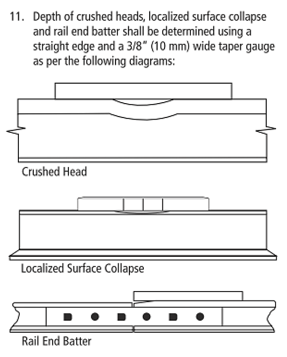
1.10 Rail end batter, localized surface collapse, and crushed head rail surface conditions
Rail end batter (REB) occurs at a rail joint when the ends of the rail heads within the joint are mismatched and/or the gap between the rail ends is too large. REB is indicative of degrading joint support that can result in excessive joint movement which can be further degraded by mechanical interaction from repetitive wheel loadings. If not properly addressed in the field, REBs can ultimately result in joint failure and derailment.
A localized surface collapse is characterized by plastic metal flow, leading to the flattening out and deformation of the rail head above the plane of the rail head / web fillet (Figure 12). A crushed head (CH) is similar to a localized surface collapse (LSC) with the exception that CH deformation of the rail head extends to below the plane of the rail head /web fillet. LSCs and CHs are normally caused by mechanical interaction from repetitive wheel loadings. They can result in high contact stresses and can lead to or accelerate the development of other rail defects such as a transverse detail defect (TDD) or a vertical split head (VSH) which can fail rapidly and result in a derailment.
Rail flaw technology to detect LSC, REB, and CH conditions is relatively new. CN has recorded surface conditions such as LSCs, CHs, and REBs since 2005. In 2010, more defined guidelines for these types of conditions were introduced. Since that time, there has been a significant increase in the number of conditions detected. Some railways have developed comparable, but not harmonized, thresholds to detect and record these conditions. Before this technology was implemented, these conditions were usually detected by visual inspection, but relatively few were identified. After this technology was implemented, the number of these rail surface conditions identified has significantly increased.

Although CN considered the workforce to be adequate and properly equipped, the larger number of LSC, REB, and CH rail surface conditions that were identified represented a significant increased workload. This was especially true in the spring, when the workforce was actively engaged in removing rail plugs and rail joints installed in CWR territory during the winter months when rail defects were removed. Each LSC, REB, and CH rail surface condition had to be monitored and measured, and then removed if the standards specified in CN ETS TS 1.7, "Rail Testing and Remedial Action for Broken Rail", were exceeded. The standards identify that:
- Item 10a requires the monitoring of LSC conditions that are less than 5 mm in depth, on rail worn to less than 75% of the vertical rail wear condemning limit.
- Item 10b outlines the limits for REB in the winter months:
During the winter months (as determined by the Regional Chief Engineer), the following applies to in-track rail joints in Class 3 track and greater with annual MGT's of 10 or greater.
If joint rail end batter is found to be it. [ sic.
| > 3.5 mm | > 4 mm | >= 5 mm |
|---|---|---|
|
|
|
The depth of an LSC or REB is measured using a straight edge, as shown in Figure 13.
The TSR contain no guidance or condemning criteria for LSCs, REBs or CHs. In Canada, they are categorized as rail surface conditions rather than rail defects. While they are not considered service failures, they are considered to be leading indicators of degrading track condition and potential emerging rail defects.
In comparison, the U.S. Department of Transportation (DOT) (i.e., the Federal Railroad Administration (FRA)) considers "flattened rail,"Footnote 22 the FRA equivalent of LSC, to be a defect when it is 3/8 inch or more in depth and 8 inches or more in length. Remedial action for this defect consists of limiting operating speed over a defective rail to 50 mph or to the maximum allowable speed permitted for the class of track concerned, whichever is lower.Footnote 23
1.11 Vertical split head rail defects
A VSH defect is a progressive longitudinal fracture through or near the middle of the rail head, extending into or through it. The origin is web streaking and segregation that create an internal longitudinal seam. Web streaking and segregation are indications that inclusions in the steel have congregated along the centreline of the rail rather than being evenly distributed during the manufacturing process. Vertical separation will progress longitudinally and vertically (parallel to the side of the head), and may gradually turn toward the gauge or the field side of the rail head. Defect growth is normally very rapid once the seam or separation has opened up anywhere along its length.
During manufacturing, rail is generally formed by rolling continuous rectangular cast steel billets through a series of rollers at controlled temperatures in a steel blooming mill. Each rail is assigned a heat number which is hot stamped on the rail web. Rails in the same heat may have different properties (and defects) depending on the quality control in the casting and rolling process. During the rolling process, some impurities can be forced into the centre of the rail web. When subjected to macroscopic examination, the impurities display as a tight seam within the web. On some occasions, the seam extends into the head of rail. This becomes problematic when the rail head wears down and the seam is exposed to dynamic loading due to service conditions (i.e., wheel loads as they traverse the rail). Once exposed to dynamic loading, the seam, which is not detectable by rail flaw detection until it opens, can rapidly deteriorate and result in a VSH rail failure.
Sydney Steel CompanyFootnote 24 had experienced a number of process and quality control problems with its rail manufacturing throughout its history. One problem had been the presence of centreline streaking that extended into the rail head. Once a rail head had sufficient wear, the tip of the centreline streaking was in an area of the rail head that was subjected to the highest rolling contact forces, making it more susceptible to rapid VSH development and fracture propagation.
The U.S. Department of Transportation FRA Title 49 CFR, Part 213, Track Safety Standards: Improving Rail Integrity: Final Rule, dated 24 January 2014, discusses the development of internal rail flaws and the risk of failure. The Final Rule states that, in practice, the growth rate of rail defects is considered highly inconsistent and unpredictable. High traffic volumes load the rail and accelerate defect growth. The tonnage required to influence defect development is also considered difficult to predict. However, once a defect is initiated, tonnage influences its internal development and growth.Footnote 25
Although difficult to detect visually, a crack or rust streak may show in the head/web fillet area under the head. There may also be signs of sagging or dropping, or pieces may split off the side of the head.
The Sperry Rail Service Rail Defect Manual.describes VSH defects as dangerous fatigue defects because:
- It is usually not visible on the rail surface until it has grown to a length of several feet.
- As VSH usually extends longitudinally for some distance, a considerable portion of the rail head is weakened.
- If the split is on the gauge side of the rail and breaks off in service, car wheels will tend to climb to the top of the rail or drop into gauge thus causing a derailment.
- When the rail breaks in-service, it may break into several pieces.Footnote 26
VSH defects are a common fatigue defect and considered dangerous given that they can develop rapidly and their presence is difficult to detect, even with ultrasonic inspection. In 2014, Sperry Rail Service detected a total of 33 241 defects while testing 134 054 miles of CN track in Canada. VSHs accounted for 1533 (4.6%) of these defects. During the same period, CN reported 692 rail in-service failures, 76 (11%) of which were due to VSH defects.
1.12 Plug rail repair at Mile 88.75
The CTC signal control system on the Ruel Subdivision is divided into a series of sections or "blocks" that are electrically isolated from each other. Signals at each end of a block control movements into and out of that block. When a train is in a block, signals at each end of the block are RED, meaning "stop", and the RTC display will indicate that the block is occupied. Signals can also default to a RED indication when a broken rail occurs in the block.
On 04 March 2015, at about 1935, the signals controlling traffic into the Gogama-Bethnal block (Mile 86.20 to Mile 94.70) unexpectedly changed to a RED indication, prohibiting rail traffic from entering the block. Therefore, it was necessary to quickly find the source of the RED signal activation.
The regular track maintenance foreman (TMF) was not available, because he had been called out to replace a defective rail east of Gogama. The track supervisor (TSPVR) instructed the snow patrol foreman (SPF), who was a thermite welding foreman during the summer, and a helper on light duties who was unable to assist much physically, to determine the source of the RED signal activation. At 2021, the SPF obtained a track occupancy permit (TOP) and proceeded by high-rail vehicle to investigate. The SPF was followed by a signal maintainer on the same TOP. At about 2050, the SPF, the helper, and the signal maintainer located a broken thermite weld in the south rail at Mile 88.75.
The SPF took a picture of the broken rail, sent it to the TSPVR, and requested instructions on how to proceed. Given the 4-inch offset of the broken rail, the TSPVR indicated that the broken rail would need to be changed out before any trains would be able to pass over the area. However, the section work crew was at the end of its shift and nearing the end of available hours to operate the track force optimization (TFO) vehicle. The TSPVR instructed the SPF and the helper to change out the rail. The SPF was also a qualified track foreman and, as such, was considered qualified to change out the broken rail.
The signal maintainer measured the rail head loss of the broken rail and notified the Gogama TMF that they would require a plug rail with 8 mm of head loss. The SPF proceeded to Gogama, where he met with the section work crew. A 157-inch plug rail with 8 mm of rail head loss was loaded on to the TFO vehicle. This plug rail had pre-drilled holes for joint bar bolts at one end. As the SPF was not familiar with the TFO vehicle, the section work crew provided the SPF with a familiarization briefing before the crew went off duty. Once briefed, the SPF drove to the Highway 144 crossing, put the TFO vehicle onto the track, and proceeded east to the site of the broken rail.
After arriving on site, the SPF prepared for the installation of the plug rail. The plug rail was unloaded and positioned. Snow and ice was cleaned away from the parent rail. A mark was made on the parent rail 68 inches west and 78 inches east of the broken weld to position the plug rail ends between ties. Eleven inches of material was cut from the plug rail. The parent rail was cut and the exposed rail ends were visually inspected for cracks or other anomalies.Footnote 27 No cracks were visually observed; however, a dye penetrant test was not performed to confirm the presence of any cracks. The CN requirement to perform a dye penetrant test on the exposed rail ends had not specifically been discussed between the SPF and the TSPVR.
The plug rail was rolled into the track with no joint gaps. Because the east end of the plug rail was pre-drilled for 132-pound joint bars,Footnote 28 only the west end of the plug rail had to be drilled. However, the drilling template was placed on top of the plug rail in a way that resulted in the outside hole being drilled too close to the joint. Consequently, an extra hole had to be drilled in the plug rail. The two holes were about ½ inch apart. This situation was discussed with the TSPVR, and the rail repair was approved for service. Once the drilling was complete, the plug rail was fully bolted, spiked, and anchored.
While the repair was being performed, the SPF received several phone calls and radio calls from the TSPVR, the RTC, and the Senior Manager Engineering (SME) for progress updates. The SPF was informed that a number of eastbound and westbound trains were already waiting.
The plug rail was not physically measured after the repair, but the SPF visually estimated that it was 2 mm higher than the parent rail at the east end of the installation. The SPF used a hand grinder to ease the transition between the two surfaces by grinding the top of the rail for about 2.5 inches from the east end of the plug rail. The hand grinder was used because the larger rail grinder was not available.
The work was completed at about 2245. The SPF cleared the track and drove back to the tool house to prepare for snow clearing duties for the remainder of the shift. The TOP was cancelled at 2307:40, and rail traffic was restored.
The TSPVR had intended to check the broken rail repair to ensure that it had been properly completed. However, the TSPVR became occupied the following morning responding to another derailment near Minnipuka, Ontario (Mile 243.50 on the Ruel Subdivision).
Between the time that the track repair was completed on 04 March 2015 and the occurrence on 07 March 2015, 44 trains, including other crude oil unit trains, had traversed the plug rail.
1.13 Snow patrol foreman and helper information
The SPF joined CN in 1998 and worked as a thermite welding foreman on production gangs during the summer, which primarily involved welding new rail to new rail. At the end of the summer/fall work season, the SPF became part of CN's winter workforce. At the time of the occurrence, the SPF was on snow clearing duties and was working a 9 days on, 5 days off cycle on the night shift, stationed at Gogama.
The helper had worked as a machine operator for CN for 8 years. On 03 March 2015, the helper had been sent to Gogama to work with the SPF while the regular machine operator was away. The helper was on light duties and had little experience in changing out broken rails and performing plug rail repairs.
1.14 Installing plug rails
The process for changing out a broken or defective rail and the related training were covered in various CN training classes and documents. Specifically, the installation of plug rails was covered in the Track Maintainer course and in an on-the-job training manual. Handling the rail with a crane was covered in the Crane Fundamentals course and the Crane Handbook. The standards regarding match marks, dye penetrant, and plug rail length were covered in CN's Engineering Track Standards.(June 2011) (ETS) and Recommended Methods (RM).
CN ETS TS 1.2, "Laying Rail - General," Item 13, states (in part) that
Item 13 further specifies the track speed reductions that are required if such repairs cannot be carried out immediately. This section of the ETS contains no guidance on the length of grinding required to provide a smooth transition between rail sections of plug rail repairs. In comparison, the CN Welders Manual.(2005), Chapter 17, states (in part):
- for flash butt welding, the maximum vertical offset for two rails thermite welded together must not exceed 1/8 inch (0.125 inches) [3 mm]; and
- if a difference in height exists, it should be corrected by grinding the high rail over a distance of 6 inches for every 0.01 inch of offset up to a maximum of 36 inches.
CN ETS section 1.7(2) states (in part):
Regarding dye penetrant testing, ETS 1.7(3) states (in part):
Dye penetrant testing shall be performed on rail ends:
- in the event of an in-service rail failure;
1.14.1 Dye penetrant testing
The required steps to perform when testing the rail with dye penetrant are listed in CN Recommended Method (RM) 1.7.3 (January 2015).
Dye penetrant testing is a 3-step process that involves spraying a cleaner, a penetrant, and a developer chemical on the exposed cut of the rail end. The test takes about 15 minutes to perform and can be done while preparing the plug rail for installation.
This test is based on capillary action, where a low-surface-tension dye penetrant fluid is sprayed on a rail end. After time has been allowed for penetration, excess penetrant fluid is removed and a developer is applied. The developer helps draw the penetrant out of a flaw or crack and onto the surface, making the crack visible. Dye penetrant testing can be conducted on rails at temperatures as low as −32 °C. However, for best results, both the penetrant and the developer should be kept warm. In cold weather, the penetrant should be sprayed on the rail ends immediately after the rail has been cut, as the heat from cutting will aid in opening any cracks that may be present.
1.14.2 Snow patrol foreman's familiarity with dye penetrant testing
The SPF was aware of the dye penetrant test but had never done it before or seen it done. When working as a thermite welding foreman, the SPF had worked primarily with new rail. The dye penetrant test was typically conducted for older rails removed from track due to an in-service failure.
On 27 January 2015, the SPF took the CN Engineering winter safety online exam, which included some questions about dye penetrant testing. The passing grade for the exam was 90%. On the first attempt of the exam, the SPF obtained a mark of 74% and had 12 incorrect answers, including a question about the dye penetrant testing. On the second attempt, the SPF answered the dye penetrant question correctly and obtained a mark of 96%.
1.15 Procedural errors
Errors of omission, including skipping steps in a maintenance procedure, have been shown to be among the most frequent errors during maintenance activities. These types of errors are more likely to occur in situations where the required step is not critical to achieving the main goal of the maintenance activity or takes place after the main goal has been achieved, and where there are few environmental triggers to remind the maintainer that a step needs to be performed. Tasks that have recently changed, or need to be conducted in a manner or order that is unusual for the maintainer, are also more prone to errors of omission.Footnote 29
In situations where reminders cannot be built into the maintenance task itself, external reminders are the simplest countermeasure to ensure that critical steps are completed. To be effective, reminders need to be timely (visible at the appropriate time) and compelling (prevent the task from being completed without a procedural check). Commonly used means of building these characteristics into a reminder include the use of checklists or task cards for commonly performed maintenance tasks and independent checks of critical maintenance activities before returning equipment to service.
1.16 Canadian National Railway Company engineering employee development
Unionized engineering employees were initially hired as track maintainers. Track maintainer training consisted of a 3-week course at CN's training centre in Winnipeg. The first week covered general introductory topics related to working for CN, the second week was specific to the role of a track maintainer, and the third week was devoted to CROR training.
Candidates were required to pass an exam related to track maintenance at the end of the second week in order to proceed to rules training. There were very few failures at this stage of the training. A rules test was administered at the end of the third week. About 75% of the candidates successfully passed the rules test on their first attempt. Candidates who were unsuccessful could attempt the test a second time after 90 days of field experience. The success rate on the second attempt was approximately 95%.
Once qualified as track maintainers, employees could bid to become a track foreman (TF). The TF course was a 10-day course and included a number of mandatory courses, including track inspection guideline (TIG) training, CWR training, and crane qualification. TFs were required to renew their TIG and CWR training every 3 years; this was tracked through CN's training management system.
1.17 Canadian National Railway Company engineering organization on the Ruel Subdivision
CN's Ruel Subdivision extends westward for 296.2 miles from Capreol (Mile 0.0) to Hornepayne (Mile 296.2). To facilitate track inspection and maintenance activities, the subdivision is divided into an eastern portion (from Mile 0.0 to Mile 183.2) and a western portion (from Mile 183.2 to Mile 296.2).
On the eastern portion of the Ruel Subdivision, a TSPVR and 2 ATSs were responsible for all maintenance activities, including the supervision of all related engineering maintenance personnel. One ATS was responsible for about 87 miles at the east end of the eastern portion, and the other ATS was responsible for about 97 miles at the west end of the eastern portion. Track maintenance personnel consisted of about 18 to 24 permanent employees during the summer. About 34 temporary employees were added during the winter.
The TSPVR reported to the senior manager engineering (SME) for the Northern Ontario Zone. The SME was 1 of 4 CN SMEs within the province of Ontario and was responsible for a territory which included parts of the Bala, Caramat, and Newmarket Subdivisions, and all of the Ruel and Soo Subdivisions. The SME reported to 1 of 2 assistant chief engineers for CN's eastern region, who in turn reported to the eastern regional chief engineering.
1.18 Track maintenance challenges on the Ruel Subdivision
CN identified train velocityFootnote 30 as an issue having significant influence on the use of assets and cost control, which are 2 of CN's 5 strategic business pillars.Footnote 31 All engineering employees understood the sense of urgency to move trains as quickly and as safely as possible.
Train delays that affect velocity can create inter-functional pressures within the company. These pressures can sometimes create conflict between track maintenance decisions and train operations. Because of the importance of keeping trains moving, it can be challenging for track maintenance personnel to obtain adequate track time to conduct the required track inspection, maintenance, and repairs, particularly in a remote territory with limited road access.
1.19 Regulatory oversight
TC promotes safe and secure transportation systems in the air, marine, rail, and surface modes, as well as the safe transportation of dangerous goods (DGs). To do so, TC develops safety regulations and standards, and, in the case of railways, it facilitates the development of rules by the rail industry. Once the rules are approved, TC is then responsible for enforcing the rules through a number of inspection programs to monitor compliance with rules and regulations. Track inspections are targeted using a risk-based approach. TC also has a national inspection program that randomly selects track segments to be inspected each year. Primary traffic corridors usually receive more attention than secondary main lines.
Rail safety is governed by the Railway Safety Act, the objectives of which are to:
- promote and provide for the safety and security of the public and personnel, and the protection of property and the environment, in railway operations;
- encourage the collaboration and participation of interested parties in improving railway safety and security;
- recognize the responsibility of companies to demonstrate, by using safety management systems and other means at their disposal, that they continuously manage risks related to safety matters; and
- facilitate a modern, flexible and efficient regulatory scheme that will ensure the continuing enhancement of railway safety and security.Footnote 32
TC has also developed the Railway Safety Management System Regulations.(SMS Regulations), which require railways to manage their safety risks.
1.20 Transport Canada regulatory track inspections
TC railway engineering inspectors are tasked with conducting railway infrastructure inspections across Canada. Railway subdivisions are not necessarily subject to regular TC inspections. Instead, TC uses a risk-based approach that considers various factors to identify specific subdivisions or areas of subdivisions that require targeted inspection. TC prioritizes inspections by considering different operational factors, including but not limited to rail and geometry defects, number of passenger trains, operating speeds, and traffic tonnage. Emerging track conditions such as LSCs and REBs, which are not considered defects under the TSR, are not specifically considered as part of the risk-based approach.
The TC inspection program has 3 components:
- A-component inspections: TC Headquarters develops a national inspection plan for the following year using a statistical model, identifies the number of inspections, and targets companies that are to receive these inspections.
- B-component inspections: TC regions focus on specific recurring issues requiring closer monitoring using a risk-based business planning process to identify the companies that are to receive these inspections.
- C-component inspections: These are unplanned and respond to issues emerging through the year, such as derailments and ad hoc inspections.
Using the national inspection plan, each TC region develops an operational plan to provide guidance to its rail safety inspectors on which companies, infrastructure locations, subdivision portions, operations, and maintenance employees to inspect. In TC's Ontario Region, each functional group performs a risk assessment to rank the subdivisions, yards, and maintenance facilities according to risk. Factors considered include accident history, compliance with standards and regulations, changes in operations, amount and type of traffic, hours of work, type of work performed, previous TC and railway inspections, and maintenance history. A significant increase in overall freight or DG traffic may be considered but does not necessarily influence which subdivisions are scheduled for inspection. Because LSCs are considered to be a condition and are not recognized as a defect in the TSR, any increase in LSC volume may not necessarily be reviewed, despite LSCs being leading indicators of a deteriorating rail condition. From the risk assessment, the inspections are prioritized so that locations or railway activities that have higher risk are inspected in a timely manner.
Table 4 summarizes the track inspections conducted by TC on the Ruel Subdivision since 2005.
| Year | From Mile | To Mile |
|---|---|---|
| 2005 | 148.3 | 223.5 |
| 2006 | 87 | 183 |
| 2007 | 0 | 86.7 |
| 2008 | 0 | 87 |
| 2010 | 87 | 127 |
| 2012 | 86 | 296 |
| 2013 | - | - |
| 2014 | - | - |
| 2015 (until February 2015) | - | - |
Between 2013 and the date of the occurrence, TC did not perform any track inspections on the Ruel Subdivision because geometry defects appeared to be declining. Following the accident, between 15 March 2015 and 19 March 2015, TC inspected the entire Ruel Subdivision and identified 67 non-compliant conditions that required remedial action and 59 other concerns and observations. These conditions had likely evolved since the last TC regulatory inspection (in 2012) and had existed before the accident, yet went undetected despite regular railway inspection.
1.21 Other TSB investigations involving regulatory inspections
Since May 2014, there have been 5 other TSB investigations where railway and/or TC inspections did not identify degrading track conditions, resulting in further deterioration of the track structure which ultimately led to a derailment (Appendix A). In 3 of the 5 occurrences, track joint or rail failure occurred in the immediate vicinity of pre-existing LSC or REB rail surface conditions which, although not condemnable, were being monitored at the time.
1.22 TSB safety issues investigation
In response to a series of train derailments on secondary main lines involving broken rails in the winter of 2003–2004, the TSB carried out a safety issues investigation.Footnote 33 The study established a significant relationship between rail defects and the level of bulk unit train traffic and found that the effect of increasing bulk train traffic had not been accommodated through regular maintenance. The same circumstances could also apply to mainline track. The study also identified that
- Railways recognized that the rate of track degradation was accelerated with increases in bulk unit train tonnage. However, an appropriate balance between increased track degradation and timely infrastructure maintenance and/or renewal was not always achieved.
- Compliance with the TSR in and of itself was insufficient to ensure safety since it did not provide a means to anticipate changing conditions such as increased traffic over the long term.
- There was a need for more proactive safety management system (SMS) processes to anticipate operational conditions which could lead to a degradation of safety margins.
1.23 Safety Management System Regulations
An SMS is "a systematic, explicit and comprehensive process for managing safety risks."Footnote 34 It is a means to ensure that a railway has the processes in place to identify the hazards in its operation and mitigate the risks. SMS was designed around evolving concepts about safety that are believed to offer great potential for more effective risk management. SMS was progressively introduced in the Canadian transportation industry because this approach to regulatory oversight, which seeks to ensure that organizations have processes in place to manage risks systematically, when combined with inspections and enforcement, is considered to be more effective in reducing accident rates.
Section 2 of the TC Safety Management System Regulations (2001).(the SMS Regulations), which were in force at the time of the accident,Footnote 35 states:
- A railway company shall implement and maintain a safety management system that includes, at a minimum, the following components:
- the railway company safety policy and annual safety performance targets and the associated safety initiatives to achieve the targets, approved by a senior company officer and communicated to employees;
- clear authorities, responsibilities and accountabilities for safety at all levels in the railway company;
- a system for involving employees and their representatives in the development and implementation of the railway company's safety management system;
- systems for identifying applicable
- railway safety regulations, rules, standards and orders, and the procedures for demonstrating compliance with them, and
- exemptions and the procedures for demonstrating compliance with the terms or conditions specified in the notice of exemption;
- a process for
- identifying safety issues and concerns, including those associated with human factors, third-parties and significant changes to railway operations, and
- evaluating and classifying risks by means of a risk assessment;
- risk control strategies;
- systems for accident and incident reporting, investigation, analysis and corrective action;
- systems for ensuring that employees and any other persons to whom the railway company grants access to its property, have appropriate skills and training and adequate supervision to ensure that they comply with all safety requirements;
- procedures for the collection and analysis of data for assessing the safety performance of the railway company;
- procedures for periodic internal safety audits, reviews by management, monitoring and evaluations of the safety management system;
- systems for monitoring management-approved corrective actions resulting from the systems and processes required under paragraphs (d) to (j); and
- consolidated documentation describing the systems for each component of the safety management system.Footnote 36
The SMS Regulations also require railway companies to
- maintain records to permit the assessment of safety performance (subsection 3(1));
- submit documentation and records to the Minister that demonstrate compliance with the regulations (subsection 4(1)); and
- produce safety management documentation upon request (section 6).
1.24 Canadian National Railway Company's safety management system
In accordance with the SMS Regulations, CN had developed and implemented a detailed SMS. Since 2008, CN's SMS had been enhanced each year and had been integrated into most facets of its operations. The SMS described company initiatives that correlate to the requirements of section 2 of the SMS Regulations .
With regard to paragraph 2(e) of the SMS Regulations that were in force at the time of the occurrence, CN had implemented systems for
- identifying safety issues and concerns, including those associated with human factors, third-parties and significant changes to railway operations;
- evaluating and classifying risks by means of a risk assessment; and
- identifying and implementing risk control strategies.
Specific actions included the following:
- Safety issues and concerns were flagged to CN management through hazard forms, health and safety committees, CN's Ombudsman and CN's Prevent Hotline (a joint venture with Saint Mary's University, Halifax, Nova Scotia), as well as through audits and trend analyses.
- CN had a formal risk assessment process that was used to evaluate and classify risks, including those associated with significant changes in railway operations, such as the opening of new yards and facilities, railway acquisitions, introduction of new technology, significant changes in business (volumes or product), and changes in personal protective equipment.
- Special corridor risk assessments were being carried out to assess and reduce risk in locations with high populations, waterways, or other environmental or topographical characteristics.
- Training was being provided to employees who performed risk assessments.
When human factors may have played a role in an accident, CN required further investigation before formulating corrective action, and the following was typically considered:
- Was the work properly planned, organized and supervised?
- Was the employee properly trained and equipped?
- Did the employee have the opportunity for sufficient rest?
- Was the rule or work procedure well understood?Footnote 37Footnote 38
Despite having a formal risk assessment process, CN perceived the increased tonnage of crude oil shipments on the Ruel Subdivision during the 2014 year as a normal operating parameter. The increase in tonnage did not trigger CN to conduct a risk assessment or to review an existing one.
1.25 Safety culture
Safety culture can be defined as "shared values (what is important) and beliefs (how things work) that interact with an organization's structures and control systems to produce behavioral norms."Footnote 39 Safety culture is critical to effective safety management, because safety management processes will be ineffective in a culture that does not support the proactive sharing of safety information. Where a safety culture exists to support effective safety management, information pertaining to safety will be actively sought; employees will be trained to recognize hazards and rewarded for sharing safety concerns. In such a culture, failures will be scrutinized as an opportunity to learn, and new ideas will be welcomed.Footnote 40 An effective safety culture is critical to the processes required by an SMS that support the development of a resilient organization.
TC's SMS guidance document Rail Safety Management Systems Guide: A Guide for Developing, Implementing and Enhancing Railway Safety Management Systems.states that:
An effective safety culture in a railway company can reduce public and employee fatalities and injuries, property damage resulting from railway accidents, and the impact of accidents on the environment.
In simple terms, an organization's safety culture is demonstrated by the way people do their jobs—their decisions, actions and behaviours define the culture of an organization.
The safety culture of an organization is the result of individual and group values, attitudes, perceptions, competencies and patterns of behaviour that determine the commitment to, and the style and proficiency of, an organization's health and safety management system
Organizations with a positive safety culture are characterized by communications from various stakeholders founded on mutual trust, by shared perceptions of the importance of safety and by confidence in the efficacy of preventive measures.Footnote 41
The relationship between safety culture and safety management is reflected in part by the beliefs, attitudes, and behaviours of a company's management.
An effective safety culture includes proactive actions to identify and manage operational risk. It is characterized by an informed culture where people understand the hazards and risks involved in their own operation and work continuously to identify and overcome threats to safety. It is a just culture, where the workforce knows and agrees on what is acceptable and unacceptable. It is a reporting culture, where safety concerns are reported and analyzed and where appropriate action is taken. Finally, it is a learning culture, where safety is enhanced from lessons learned.Footnote 42
A company's policies determine how safety objectives will be met by clearly defining responsibilities; by developing processes, structures and objectives to incorporate safety into all aspects of the operation; and by developing the skills and knowledge of personnel. Procedures are directives for employees and communicate management's instructions. Practices are what really happens on the job, which can differ from procedures and, in some cases, increase threats to safety.
1.26 Safety culture at Canadian National Railway Company
In parallel with implementing SMS, CN had recognized the importance of building an effective safety culture which the company considered essential for SMS. To help strengthen its safety culture, CN has invested in training, coaching, and employee recognition and involvement.
In October 2014, CN co-hosted a safety culture symposium in Halifax, Nova Scotia, during which participants discussed and shared information on safety culture. CN also hosted a number of safety summits throughout its regions to promote two-way communication and best safety practices.
In 2014, among other initiatives, CN developed and implemented Looking Out for Each Other, a strategy that has become an integral part of CN's safety culture. The peer-to-peer engagement strategy was designed to
- raise awareness among employees of the top causes of incidents and injuries;
- identify and review safe work procedures;
- train employees to be aware of their surroundings and to recognize potential at-risk work practices or situations in the field;
- teach employees how to provide constructive feedback to peers; and
- learn from past incidents to prevent a reoccurrence of the same event and help each other stay safe.Footnote 43
1.27 Resilience: The safe operating envelope and requisite imagination
Resilience is generally defined as the ability to "withstand or recover quickly from difficult conditions."Footnote 44 A resilient organization or system is defined as being "able to effectively adjust its functioning prior to, during or following changes and disturbances, so that it can continue to perform as required after a disruption or a major mishap, and in the presence of continuous stresses."Footnote 45
Four cornerstones common to resilient organizations have been identified. The ability to adjust and adapt requires the organization to respond to events, monitor key change indicators, anticipate long term challenges and learn from experience. With these cornerstones in place, a resilient organization will
- know what to do (how to respond to regular events)
- know what to look for (how to monitor for potential problems)
- know what to expect (anticipating potential threats)
- know what has happened (having the right indicators to learn from experience).Footnote 46
These abilities help organizations balance potentially competing safety, efficiency, and workload pressures relevant to the operating environment.
An organization that is monitoring, anticipating, and learning effectively through proactive safety management processes and leading safety indicators will be able to respond to competing pressures and maintain an acceptable level of risk. Being poorly equipped to detect and understand the significance of small changes in the operating environment will increase risk until lagging indicators such as accidents or serious incidents provide clear indications that the system is out of balance.
One of the challenges is that safety reserves (procedures and practices that help maintain an acceptable margin of safety) can experience pressure from competing demands to increase efficiency. Mistaking safety reserves for inefficiencies will undermine safety goals.Footnote 47 Balancing competing demands is a challenge for individuals at all levels of an organization, because safety issues can emerge slowly and be difficult to detect. The human capability to appreciate the significance of information and events and to anticipate their impact on safety has been termed "requisite imagination."
Developing requisite imagination relies on individuals within the organization having
- expert track knowledge allowing anticipation and judgement of defect conditions;
- the will to think critically about the functioning of the system;
- effective training to develop these capabilities;
- sufficient spare capacity to respond to events; and
- a clear flow of information throughout the organization.Footnote 48
A comprehensive SMS would help an organization develop requisite imagination by ensuring that it has processes in place to support the 4 cornerstones of resilience, including
- effective procedures for normal and abnormal situations (responding)
- safety reporting and trend analysis (monitoring)
- risk identification and assessment (anticipating)
- incident investigation (learning).
"Proactive safety management helps organizations look ahead to notice the signs that risks are changing or increasing despite past records of success and increasing pressures for short term performance."Footnote 49 An effective safety culture is essential in order to realize the benefits of requisite imagination. The safety culture of an organization will largely determine the type and amount of information fed into safety management processes, and how such information will be received and addressed.
1.28 Significant accidents involving Class 111 tank car releases
There have been a number of occurrences in Canada and the U.S. during which product was released from Class 111 tank cars following a collision, impact, and/or fire (Appendix B). These occurrences highlight the vulnerability of Class 111 tank cars to accident damage and product release. As of June 2015, about 270 000 Class 111 tank cars were in service in North America, of which about 141 000 were being used to transport DGs.
1.29 The Lac-Mégantic accident
On 05 July 2013, at about 2250 Eastern Daylight Time, Montreal, Maine & Atlantic Railway (MMA) freight train MMA-002, en route from Montréal, Quebec, to Saint John, New Brunswick, was stopped at Nantes, Quebec (Mile 7.40 of the Sherbrooke Subdivision), the designated MMA crew-change point. The train, consisting of 5 head-end locomotives, 1 VB car (i.e., special-purpose caboose), 1 box car, and 72 Class 111 tank cars carrying flammable liquids (petroleum crude oil, UN1267, Class 3), was then secured on the main track and left unattended on a descending grade.
Shortly before 0100 on 06 July 2013, the unattended train started to move, and gathered speed as it rolled, uncontrolled, down the descending grade toward the town of Lac-Mégantic, Quebec. After reaching a speed of 65 mph, 63 Class 111 tank cars and a box car derailed near the centre of the town. The derailed cars released approximately 5.98 million litres of product due to tank car damage. The released product ignited almost immediately, resulting in a large pool fire that burned for more than a day. Forty-seven people were fatally injured.
Many buildings, vehicles, and the railway tracks were destroyed. About 2000 people were initially evacuated from the surrounding area.
As part of the Lac-Mégantic investigation,Footnote 50 the TSB highlighted the vulnerabilities of Class 111 tank cars and recommended that:
The Department of Transport and the Pipeline and Hazardous Materials Safety Administration require that all Class 111 tank cars used to transport flammable liquids meet enhanced protection standards that significantly reduce the risk of product loss when these cars are involved in accidents.
Transportation Safety Recommendation R14-01
1.30 Response from Transport Canada to TSB Recommendation R14-01 (February 2017)
In February 2017, TC provided an updated response to Recommendation R14-01. TC indicated that:
The new TC-117 regulation established the requirements for a new flammable liquid tank car standard (TC-117), retrofit requirements for older tank cars in flammable liquid service and implementation timelines to modernize the North American tank car fleet. The standards and timelines were generally harmonized with the US regulators (PHMSA and FRA).
On 13 July 2016, the Minister of Transport issued Protective Direction (PD) 38, in accordance with the Transportation of Dangerous Goods Act, 1992. This PD further accelerates the phase-out of both jacketed and unjacketed legacy DOT-111 tank cars from being used for crude oil service in Canada as of 01 November 2016.
In October 2016, a planning session was held with respect to the feasibility of further accelerating the prescribed tank car phase-out schedule. TDG has been examining options to broaden the department's scope of action in terms of the phase-out of DOT-111 and CPC-1232 tank cars. This will include: analyzing the state of the tank car industry; assessing whether sufficient tank cars exist in light of current demand for transporting flammable liquids by rail; recommending potential acceleration of the phase-out schedule where feasible, and developing an impact assessment. This will lead to recommendations on whether to further accelerate the tank car phase-out schedule introduced in May 2015 and ending in 2025. This feasibility study is expected to be completed by late 2017.
Transport Canada continues to monitor closely the construction of new TC-117 tank cars and the retrofitting of older flammable liquid tank cars. Transport Canada continues to study the possibility of further acceleration of the prescribed phase-out schedule. Transport Canada will collaborate with US DOT and industry in monitoring the flammable liquid tank car fleet.
1.31 Board assessment of Transport Canada response to TSB Recommendation R14-01 (March 2017)
In March 2017, the Board assessed TC's response to Recommendation R14-01. It was indicated that:
This recommendation is related to the TSB Watchlist issue of "Transportation of flammable liquids by rail", which was updated in 2016. The transportation of flammable liquids, such as crude oil, by rail across North America has created an elevated risk that needs to be mitigated effectively. Recommendation R14-01 is specific to new and existing Class 111 tank cars for the transportation of flammable liquids.
Transport Canada's new regulations modernizing the North American tank car fleet established a new tank car standard (TC-117) and prescribed retrofit requirements for older tank cars in flammable liquid service as well as implementation timelines. These were generally harmonized with the US regulators (PHMSA and FRA).
In July 2016, TC issued Protective Direction 38 which accelerated the phase-out of legacy DOT-111 tank cars from crude oil service in Canada as of 01 November 2016. In October 2016, a planning session was held with respect to the feasibility of further accelerating the prescribed tank car phase-out schedule, involving both DOT-111 and CPC-1232 tank cars. This feasibility study is expected to be completed by late 2017.
The Board acknowledges TC's continued efforts to monitor the construction of new TC-117 tank cars and the retrofit of older tank cars in flammable liquid service. While there are no prescribed regulatory provisions requiring industry to provide detailed fleet retrofit progress data, TC is collaborating with the US DOT and industry to monitor the state of the tank car fleet in flammable liquid service.
The Board is encouraged with the progress made to date on the phase-out of legacy tank cars in flammable liquid service and looks forward to a fleet status update following TC's collaboration with the US DOT and industry. However, until all flammable liquids are transported in tank cars built sufficiently robust to prevent catastrophic failure when involved in an accident, the risks will remain. Therefore, the Board continues to call upon TC to ensure that risk control measures during the transition and phase-out are effectively managed.
The Board considers Transport Canada's response to Recommendation R14-01 as having Satisfactory Intent.
1.32 Association of American Railroads Circular OT-55-N and TSB Recommendation R14-02
In January 1990, based on recommendations of the Inter-Industry Task Force on the Safe Transportation of Hazardous Materials by Rail, the AAR issued Circular OT-55 (OT-55), entitled Recommended Railroad Operating Practices for Transportation of Hazardous Materials. OT-55 provided the rail industry with routing guidance for selected dangerous goods, including poisonous-by-inhalation (PIH) and toxic-by-inhalation (TIH) products. Radioactive materials were added to OT-55 in August 2001. In addition, OT-55 identified the technical and handling requirements for key trains and key routes.
Following the Lac-Mégantic accident, the definition of a key train was revisedFootnote 51 within OT-55-N to include any train containing 1 or more cars of PIH or TIH material, such as anhydrous ammonia, ammonia solutions, spent nuclear fuel or high-level radioactive waste, or containing 20 carloads, or intermodal portable tank loads, of any combination of other hazardous materials.
Although OT-55-N was not applicable in Canada, CN extended these measures to its Canadian operations in August 2013. As part of a company initiative, CN conducted risk assessments for subdivisions within corridors identified as key routes.
As part of the investigation into the Lac-Mégantic accident, the TSB indicated that a similar approach based on OT-55-N, strengthened with a requirement to conduct route planning and analysis, would be a positive step to improve the safety of transporting DGs by rail for all railways in Canada. On 23 January 2014, the Board recommended that
The Department of Transport set stringent criteria for the operation of trains carrying dangerous goods, and require railway companies to conduct route planning and analysis as well as perform periodic risk assessments to ensure that risk control measures work.
Transportation Safety Recommendation R14-02
1.33 Response from Transport Canada to TSB Recommendation R14-02 (March 2017)
In March 2017, TC provided an updated response to Recommendation R14-02. TC indicated that:
Transport Canada has put in place a significant number of measures to improve railway safety including improved regulations regarding company's safety management systems, regulations prescribing fines for contraventions to the Railway Safety Act, and a new liability and compensation regime for federally regulated railways.
Transport Canada issued an Emergency Directive under the Railway Safety Act in April 2014 which required railways carrying dangerous goods to implement minimum key operating practices, including speed restrictions for trains carrying dangerous goods, and the completion of risk assessments for rail transportation routes.
In February 2016, Transport Canada approved the Rules Respecting Key Trains and Key Routes, which is a permanent rule for the safe transportation of dangerous goods by rail. This rule requires railway companies that operate key trains to not exceed 50 mph, and it places a further reduction on speed to a maximum of 40 mph for key trains operating in highly urbanized areas.
For companies operating Key Routes, the rule expands requirements for inspection of track and requires defective equipment detectors. The rule also requires more robust Key Route risk assessments to be conducted at a minimum of every three years, based on minimum of 28 factors such as, volume and type of dangerous goods transported, population density along the route, and emergency response capability along the route.
Self-reporting by railways has indicated that, for Class 1 railways (Canadian National and Canadian Pacific), 95% or greater of their core networks are Key Route miles. As part of their Key Route risk assessment, railway companies are required to identify, evaluate and compare alternative routes over which the company has the authority to operate. In addition, the rule requires companies to incorporate input from municipalities and other local governments into their risk assessments.
Transport Canada's oversight activities include monitoring the safety of railway companies' operations, as well as compliance with rules, regulations and standards through audits and inspections, and taking appropriate enforcement action as required. Oversight of the new rules has been integrated into the oversight plan and continues to be an area of priority.
The requirements for risk assessment in the rule are complementary to the Railway Safety Management System Regulations, 2015 (SMS Regulations) which came into force on 01 April 2015. The SMS Regulations require a railway company to conduct a risk assessment when it has a change in operations which may affect the safety of the public or personnel or the protection of property or the environment. The following are considered circumstances requiring a risk assessment under the SMS regulation: beginning to transport dangerous goods, transporting dangerous goods different from those already carried, increasing the volume of dangerous goods carried, or changing the route on which dangerous goods are transported. The risk assessment process must describe the risks, identify remedial actions, and evaluate the effectiveness of remedial actions.
Transport Canada inspectors can use a variety of tools to address non-compliance. On 01 April 2015, new Administrative Monetary Penalty Regulations came into force under the Railway Safety Act. Since then, Railway Administrative Monetary Penalties (fines) have been issued by Transport Canada for non-compliance.
In its June 2014 assessment of TC's response to recommendation R14-02, the TSB stated:
The Emergency Directive will require risk assessments to be conducted on key routes over which key trains operate. However, key routes are defined as a route over which 10,000 car loads of dangerous goods are transported annually. This threshold may limit the number of routes subject to these enhanced safety measures. A rigorous analysis should be conducted of the 10,000-car threshold to determine which routes will be excluded and whether the safety deficiency identified in R14-02 will be addressed.
In response to this assessment, TC committed that it would review the 10,000 car loads threshold to define Key Routes.
TC and the National Research Council Canada recently completed a study which included scientific and engineering analysis to connect the volume of dangerous goods transported (in terms of car loads) in the context of risk factors within the Canadian rail network (such as railway infrastructure conditions, operation and maintenance practices) correlated with traffic volumes, and potential consequences to safety of population exposed along the route, the environmental consequences to waterways and parklands, as well as the economic consequences to rail transportation in Canada.
The study illustrated that risk is influenced by more than the number of car loads of dangerous goods which are carried. Other factors such as operating and maintenance practices of railways, infrastructure conditions, as well as population density and environmental conditions along the route also strongly influence risk.
At the current volume of dangerous goods being transported, the study found the impact of reducing the Key Route threshold was low. In the case of Class 1 railways (CN and CP), the majority of their mainline subdivisions are already Key Routes. Shortline railways generally transport an annual average of dangerous goods car loads much lower than 10,000.
In addition, Class 1 railway subdivisions analyzed in the study have relatively flat safety risk gradients, meaning that based on current operating conditions, their risk level does not appear to increase or decrease by much with changes in volumes of dangerous goods transported.
The study reinforced TC's current risk-based approach to oversight by concluding that a targeted oversight approach, on an on-going basis, to identify subdivisions with the highest risk gradient and risk level, would be the most effective approach.
Taking into account the outcomes of the study, the Department has decided the threshold for defining a key route will remain at 10,000 car loads in the Rule. Going forward, TC will incorporate outcomes from the study, with respect to identifying subdivisions with the highest risk gradient and risk level, to inform and enhance its oversight of railways operating Key Trains and Key Routes.
Transport Canada has implemented a series of integrated measures that improve safety and reduce risk for the transportation of dangerous goods by rail. These measures respond to all aspects of Recommendation R14-02.
1.34 Board assessment of Transport Canada response to TSB Recommendation R14-02 (March 2017)
In March 2017, the Board assessed TC's response to Recommendation R14-02. It was indicated that:
This recommendation is related to the TSB Watchlist issue of "Transportation of flammable liquids by rail". The transportation of flammable liquids, such as crude oil, by rail across North America has created emerging risks that need to be effectively mitigated.
In February 2016, Transport Canada approved the Rules Respecting Key Trains and Key Routes, which is a permanent rule for the safe transportation of dangerous goods by rail. This rule requires railway companies that operate Key Trains to not exceed 50 mph, with a further speed reduction to a maximum of 40 mph for Key Trains operating in highly urbanized areas. This rule requires increased frequencies for rail flaw inspections and geometry inspections for some classes of track on Key Routes. In addition, there are enhanced joint bar inspection requirements for Key Routes. The rule also requires railways to install wayside defective bearing detectors on Key Routes, and to ensure that trains do not proceed more than 40 miles without a roller bearing inspection.
About 95% of the core networks for Class 1 railways are Key Routes. Key Route risk assessments have been conducted and will be conducted every 3 years (at a minimum). These risk assessments considered 28 specific factors to assess the safety and risk for each Key Route. However, in conjunction with these assessments, railway companies should also proactively anticipate the impact of certain risk factors, such as the increase in traffic tonnage, the increased use of heavier rail cars and the potential for more rapidly degrading track structure. This approach will help ensure that track on Key Routes is maintained to the required standards and that the risk of track infrastructure failure is appropriately mitigated. As part of the Key Route reviews, the railways must also incorporate input from municipalities and other local governments into their risk assessments. Railway companies must then identify, evaluate and compare alternative routes over which the company has the authority to operate.
The requirements for the Key Route risk assessments are complementary to the Railway Safety Management System Regulations, 2015 (SMS Regulations) which came into force on 01 April 2015. Circumstances requiring a risk assessment under the SMS regulation include: transporting dangerous goods different from those already carried, increasing the volume of dangerous goods carried, or changing the route on which dangerous goods are transported.
TC recently completed its study to determine the appropriate threshold criteria on key routes. The study indicated that risk is influenced by more than the number of car loads of dangerous goods carried. Other factors that were found to influence risk included operating and maintenance practices of railways, infrastructure conditions, population density, and environmental conditions along the route. As such, TC decided that the threshold for defining a Key Route will remain at 10,000 car loads. TC believes that the study outcome reinforces its risk-based approach to oversight and that identifying subdivisions with the highest risk gradient and risk level is the most effective approach. TC will use the outcomes from the study to help identify the subdivisions with the highest risk levels in order to enhance its oversight of railways operating Key Trains and Key Routes.
Moreover, TC had previously indicated that, through its risk-based planning process, it would review all federally regulated railways to identify those that transport crude oil, but do not meet the 10,000 car load threshold on their routes. Through this risk-based approach, TC would assign appropriate resources to further monitor these railway operators. TC's national oversight plan includes a dedicated inspection program for railways operating Key Trains, including those that do not meet the 10,000 car load threshold.
TC's risk-based planning process should ensure that all federally regulated shortline railways are assessed for risk and are appropriately monitored with respect to route planning and analysis. However, this process must also ensure that any future increases in the volumes of crude oil being transported by shortline railways are considered and that any necessary adjustments are made to the risk-based approach.
The Board acknowledges TC's progress on a number of integrated measures relating to route planning and analysis for trains transporting dangerous goods. However, some TSB investigations have shown that railway companies have not always effectively managed the emerging risks to railway infrastructure associated with transporting increased volumes of dangerous goods.
The Board reassesses TC's response to Recommendation R14-02 as having Satisfactory Intent.
1.35 Census metropolitan area
A census metropolitan area (CMA), as defined by Statistics Canada, is an area of one or more neighbouring municipalities situated around a core. A CMA has a total population of at least 100 000, of which 50 000 or more live in the core. A census agglomeration (secondary core) has a population of at least 10 000. Most CMAs are geographically located on a major rail line.
According to Statistics Canada:
- The population of Canada was about 36 286 400 as of 2016.
- The town of Lac-Mégantic had a population of 5932 people (2011 census).
- The town of Gogama had a population of 277 people (2011 census).
- In 2016, there were 33 cities that met the criteria of a CMA, with a combined total population of 25 164 200. This represents about 69% of the Canadian population (Appendix C).
1.36 Rules Respecting Key Trains and Key Routes
In response to TSB Recommendation R14-02, in April 2014, TC issued MO 14-01 which defined criteria used for identifying key trains and key routes and required railways to
- formulate rules respecting the safe and secure operations of trains carrying certain dangerous goods and flammable liquids;
- govern the route and speed of any key train to 50 mph or lower, including but not limited to a further speed restriction to 40 mph or lower for any key train transporting one or more Class 111 loaded tank cars containing a number of selected DGs, which included petroleum crude oil and petroleum distillates, in areas identified as higher risk through a risk assessment process; and
- conduct risk assessments and periodic updates based on significant change to determine the level of risk associated with each key route over which a key train is operated.
The MO was reissued a number of times to provide time for consultation and the development of industry rules. Once the rules were finalized, the MO was lifted. The Rules Respecting Key Trains and Key Routes.were approved by TC and came into effect in February 2016. Subsections 4.1 and 4.2 of the rules read as follows:
4.1 Companies must restrict Key Trains to a maximum speed of 50 miles per hour (MPH). Companies must further restrict Key Trains to a maximum speed of 40 MPH within the core and secondary core of Census Metropolitan Areas.
4.2 Companies must restrict Key Trains transporting one or more DOT-111 loaded tank cars containing UN1170 ETHANOL, UN1202 DIESEL FUEL, UN1203 GASOLINE, UN1267 PETROLEUM CRUDE OIL, UN1268 PETROLEUM DISTILLATES, N.O.S., UN1863 FUEL, AVIATION, TURBINE ENGINE, UN1993 FLAMMABLE LIQUID, N.O.S., UN3295 HYDROCARBONS, LIQUID, N.O.S., UN1987 ALCOHOLS N.O.S., UN3494 PETROLEUM SOUR CRUDE OIL, FLAMMABLE, TOXIC or UN3475 ETHANOL AND GASOLINE MIXTURE to a maximum speed of 40 MPH in areas identified as higher risk through the risk assessment process as required under item 6 of this Rule. The DOT-111 tank cars include those that are CPC-1232 specification.[Footnote 52]
With respect to the speed restriction of 40 mph for a unit train hauling Class 3 flammable liquids, no detailed engineering analysis had been performed to assess the effect of the speed reduction on the severity of a derailment.
1.37 Canadian National Railway Company corridor risk assessment
On 23 June 2014, in compliance with MO 14-01, CN submitted a risk assessment to TC for the transport of DGs on the Winnipeg–Toronto Key Route. The risk assessment evaluated each subdivision on the territory to assess areas of vulnerability in terms of
- preventing an occurrence (i.e., coverage of wayside inspection systems);
- the potential consequences associated with an occurrence (i.e., proximity to population centres and environmentally sensitive areas); and
- the ability to respond to an occurrence (i.e., locations of personnel and materials to respond to a spill).
With respect to the Ruel Subdivision, most of the required mitigations identified by the corridor risk assessment were related to the ability to respond to an emergency involving DGs, such as the need for caches of response equipment on the territory and the need to evaluate contractor coverage for emergency response.
Similarly, the risk assessment took into consideration key trains that haul Class 2.3 DGs (Toxic Gases) as well as train movements where 20 or more loaded tank cars or loaded intermodal portable tanks containing DGs are shipped.
The risk assessment process for the corridor assessment did not take current or projected future track conditions into consideration. The risk assessment also did not anticipate the increase in the transport of crude oil or the impact of the increased tonnage on the ability to maintain adequate infrastructure safety margins.
CN has processes in place to identify track infrastructure maintenance requirements. For example, rail traffic volumes and detailed track defect analyses are used to identify the need for upgrades through a capital program. This review was typically undertaken during CN's planning processes by its Engineering Department. However, the information was not integrated into the corridor risk assessment, nor was it required to be. Despite these measures, the track conditions on the Ruel Subdivision had continued to deteriorate.
1.38 Factors affecting the severity of derailment of tank cars carrying hazardous materials
A 1992 study entitled Hazardous Materials Car Placement in a Train Consist.reviewed a number of National Transportation Safety Board (NTSB) derailment investigations and Federal Railroad Administration (FRA) train accident data. At the time of the study, unit trains of Class 3 flammable liquids were virtually non-existent, and Class 111 tank cars were limited to a gross rail load (GRL) capacity of 263 000 pounds. No unit DG trains were included in the study. The study concluded (in part) that:
- Railroad accident data confirms that, on the average, more cars are derailed in longer trains. To enhance hazmat transportation safety, hazmat cars should therefore be handled in somewhat shorter trains, even though it is recognized that this will result in more trains and possibly increased exposure. Exposure is, of course, route dependent and must be assessed accordingly.
- Railroad accident data also confirms that, on the average, more cars are derailed in trains at higher speeds. Hazmat cars should therefore be handled at somewhat more restricted speeds. Modest speed reductions may not necessarily result in increased exposure. This is again route dependent.[Footnote 53]
While not referenced specifically in the study, the weight of the cars involved in any derailment would also contribute to the severity of the accident.
Other more recent studies, summarized in 2014,Footnote 54 have shown that the number of cars derailed is influenced by accident cause, train speed, train length, and point of derailment within a train. Specifically, broken rails result in more cars derailing than any other accident cause; higher-speed derailments result in more cars derailed; longer trains have more cars derail; and the closer a derailment occurs to the front of a train, the more cars derail.
1.39 Canadian National Railway Company derailment at Gladwick, Ontario, on 14 February 2015
On 14 February 2015, at about 2335, CN crude oil unit train U70451-10 was proceeding eastward at about 38 mph on CN's Ruel Subdivision when it experienced a train-initiated emergency brake application at Mile 111.7, at Gladwick, Ontario. A subsequent inspection determined that the 7th through 35th cars (29 DG tank cars in total) had derailed. The train was travelling at 38 mph at the time of the accident. Of the 29 derailed tank cars, 19 were breached and about 1.7 million litres of product were released to either atmosphere or surface. The product ignited, and fires burned for 5 days. About 900 feet of mainline track was destroyed. There was no evacuation, and there were no injuries. Additional information about this derailment is presented in Appendix A.Footnote 55
1.39.1 TSB safety concern regarding speed of unit trains transporting Class 3 flammable liquids
As part of the TSB investigation into the Gladwick derailment, it was determined that the speed of the petroleum crude oil unit train increased the severity of the outcome. Consequently, the Board issued the following safety concern:
1.39.2 TSB recommendation relating to maximum speed for trains transporting dangerous goods
As part of the TSB investigation into the Gladwick derailment, the Board issued a recommendation relating to the factors that increase the severity of derailments involving dangerous goods, including train speeds for various train risk profiles. The investigation report indicated that TC had recognized the role that train speed and train risk profile play in severity of the outcome of a derailment, and had put some measures in place to limit the speed of "key trains" under certain conditions. The TC-approved Rules Respecting Key Trains and Key Routes.restrict "key trains" to a maximum speed of 40 mph within the core and secondary core of CMAs. Although the restrictions contained in the rules were a step forward at the time issued, the current maximum speed of 40 mph was selected without being validated by any engineering analysis.
Therefore, the Board recommended that:
The Department of Transport conduct a study on the factors that increase the severity of the outcomes for derailments involving dangerous goods, identify appropriate mitigating strategies including train speeds for various train risk profiles and amend the Rules Respecting Key Trains and Key Routes.accordingly.
Transportation Safety Recommendation R17-01
1.39.3 Response from Transport Canada to TSB Recommendation R17-01 (May 2017)
In May 2017, TC provided a response to Recommendation R17-01. TC indicated that:
Transport Canada acknowledges the recommendation and will conduct a literature review of existing studies, beyond those the department has already reviewed. This may provide additional analysis of speed and other factors which can directly influence the severity of the outcomes of the derailment of trains carrying dangerous goods.
The results of this literature review will be used to determine whether additional scientific and engineering analysis would be meaningful to further the department's understanding of factors affecting the severity of derailments to determine whether changes are warranted to the Rules Respecting Key Trains and Key Routes.
1.39.4 Board assessment of Transport Canada response to TSB Recommendation R17-01 (July 2017)
In July 2017, the Board assessed TC's response to Recommendation R17-01 as follows:
Transport Canada has acknowledged this recommendation.
[…]
The Board notes that, although no timeline has been proposed, TC has committed to conducting a literature review of existing studies and to assessing the results of the review. However, beyond this commitment, there are no explicit plans for TC to conduct its own study on derailment severity factors.
Therefore, the Board assesses the response to Recommendation R17-01 to be Satisfactory in Part.
1.40 TSB laboratory examination of failed rail components
The following recovered rail components were subjected to detailed examination:
- A section of rail removed 3 days before the accident during the repair of a broken thermite weld in the south rail.
- A section of rail containing the east joint of the plug rail, with joint bars still holding together a section of plug rail and a fractured 20-inch-long section of parent south rail. Most of the rail head of the 20-inch section had broken off. Only a 4-inch-long piece of the rail head was recovered.
Figure 14 shows a schematic of the recovered rail pieces as they were originally located in the track.
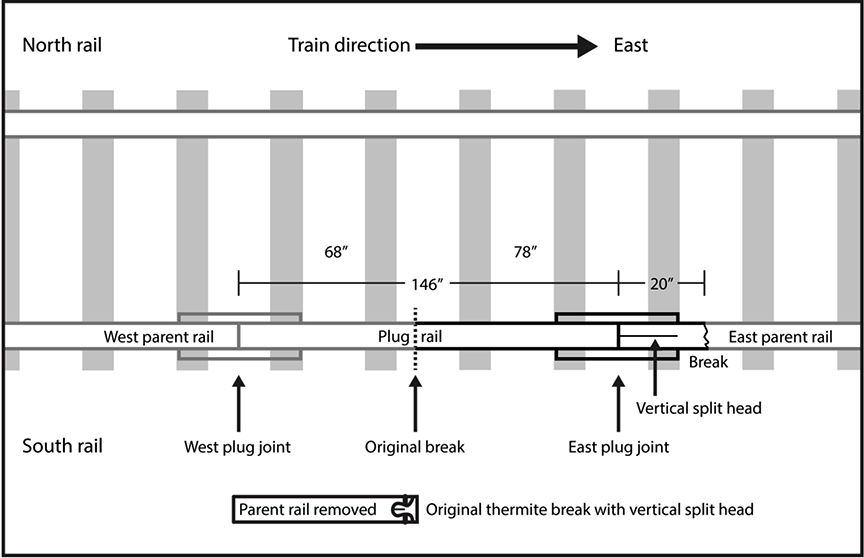
1.40.1 Original thermite weld failure
Examination of the original break at the thermite weld on the east end of the removed parent rail revealed a VSH defect in the rail head similar to the VSH defect observed in the east end joint parent rail (Figure 15).
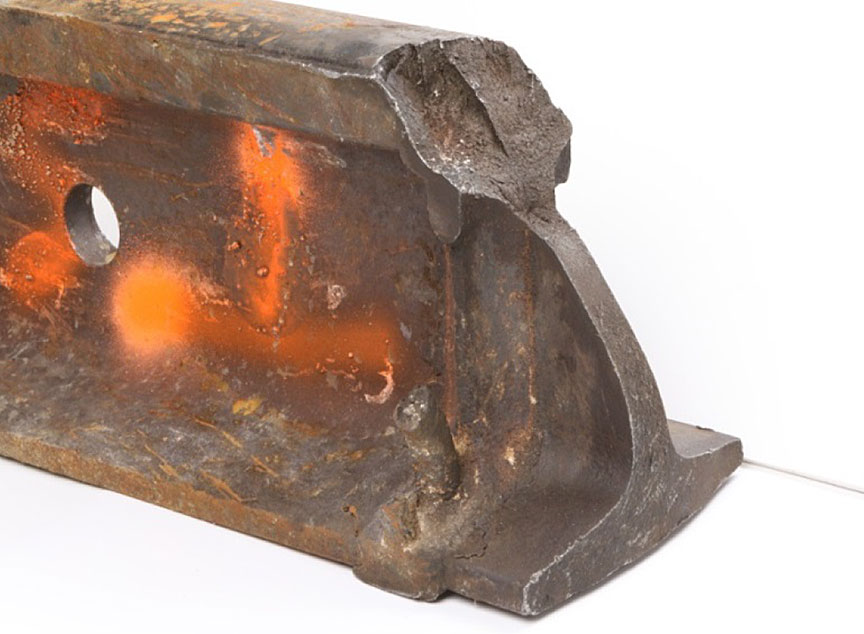
The VSH defect had propagated through the thermite weld from the original east parent rail to the west parent rail before the original rail break and plug rail repair.
During the plug rail repair, the parent rail was cut, but there was no record of non-destructive dye penetrant testing being performed on the cut rail ends. Had a dye penetrant inspection been performed, VSH indications would likely have been observed in the east cut rail end, and more of the east parent rail may have had to be removed.
With a section of the east parent rail that contained a VSH defect left in service, the defect eventually propagated to failure.
1.40.2 Section of rail containing the east end parent rail
A 20-inch section of east parent rail that had failed inside the joint and a section of the plug rail are shown as received in Figure 16.
Although no rail markings were present, the east parent rail section was identified as 136-pound rail manufactured by Sydney Steel in 1993.
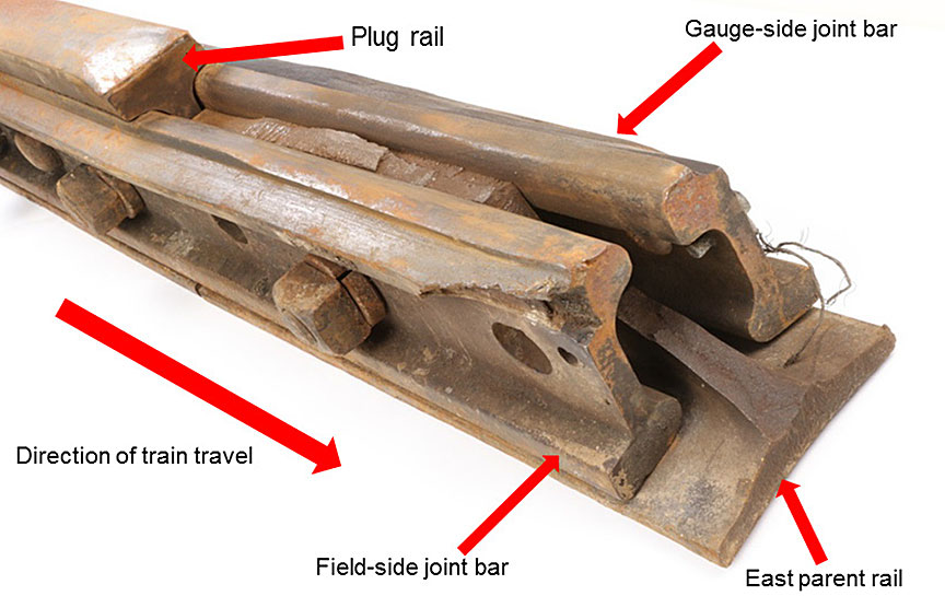
It was determined that:
- For the recovered rail, all head wear measurements were within CN specifications for rail wear.
- The hardness of the removed parent rail was within specification.
- A chemical analysis of a sample from the east parent rail met the current CN specifications for standard rail.
- The east parent rail had a region of horizontal web fracture between the joint bars and a web/base fracture east of the joint bar ends. The web fracture surface displayed pounding damage that indicated that this fracture occurred prior to the final rail failure and had remained in track for some time before the occurrence.
- When the joint bars were removed, there were no indications of movement within the joint that could have contributed to the rail break.
- The 4-inch recovered section of east parent rail head was found to mate with the horizontal web fracture. The rail head contained a VSH defect (Figure 17).
- The east parent rail material contained web streaking and centreline segregation (Figure 18). Although the extent of streaking and segregation did not exceed allowable limits, this type of microstructural defect is known to be conducive to the development of VSH defects.
- When the 20-inch section of east parent rail was placed on the same plane as the plug rail, the post-occurrence mismatch in head height measured 0.27 inch (6.75 mm) (Figure 19). For joints in Class 4 track, the allowable mismatch in rail head wear is 0.125 inch (3 mm).
- The head wear measurements were ¼ inch (6.35 mm) for the west parent rail, 3/16 inch (4.8 mm) for the plug rail, and 3/8 inch (9.5 mm) for the east parent rail. The difference in pre-accident head height between the three rails was the head wear 3/16 inch (4.8 mm) difference between the higher plug and the lower east parent rail, which exceeded the allowable mismatch for Class 4 track.
- When the plug rail was installed, the east end of the plug rail was ground down in an attempt to match the height of the parent rail. Post-occurrence measurements indicate that head grinding for a distance of about 2.5 inches (60 mm) from the end of the rail, combined with REB from the traffic over the joint after the repair, had reduced the overall height at the end of the rail by approximately 3/8 inch (9 mm).
- The CN Welders Manual.states that the maximum allowable difference in head height between two rails in a joint is 0.125 inch (3 mm) and that, if a difference in height exists, it should be corrected by grinding the high rail over a distance of 6 inches for every 0.01 inch of offset up to a maximum distance of 36 inches. The CN ETS have no clear guidance for grinding when a rail end mismatch occurs during plug rail repairs in CWR.
- Although REB and post-fracture pounding on the horizontal web fracture likely contributed to the overall mismatch of 0.375 inch (9 mm) on the occurrence rails, the mismatch at the time of the repair was at least the maximum allowable and likely up to 0.265 inches (6.75 mm). Had a similar mismatch occurred in welded rail (thermite or flash butt welded rail), the transition to the higher rail would have had to be ground back 36 inches from the mismatch.
- Prior to the plug rail repair, the east end parent rail, which also contained a VSH defect, was subjected to normal rolling stresses. After the repair, the dynamic loading created by rail wheels traversing the east end joint mismatch increased the local stresses on the east end parent rail.
- The ground 2.5-inch transition zone was significantly shorter than required, resulting in an abrupt change in rail head height and increasing the dynamic stress applied to the rail head. This increase in stress created an environment where the pre-existing VSH defect in the east parent rail could propagate rapidly.
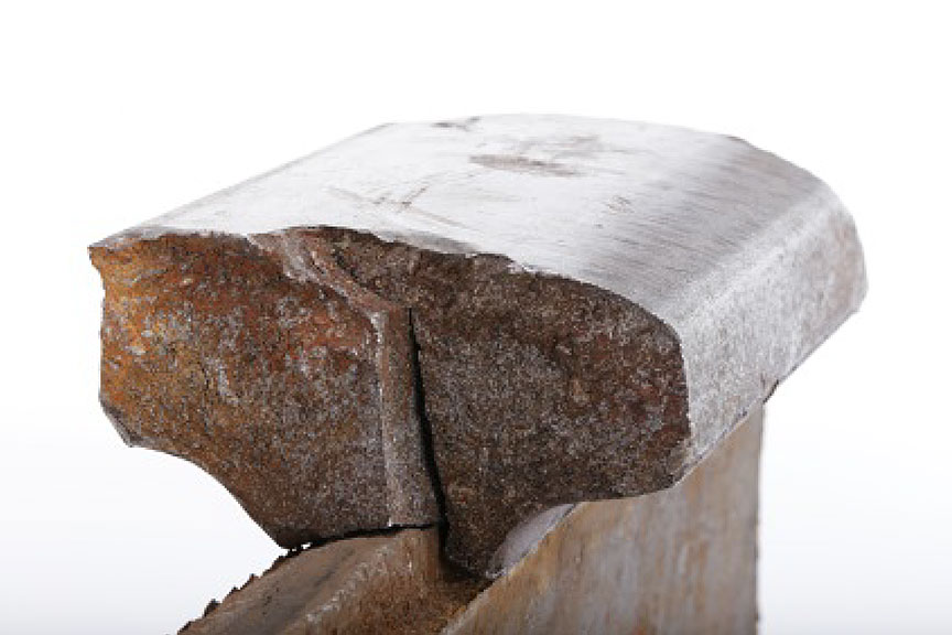
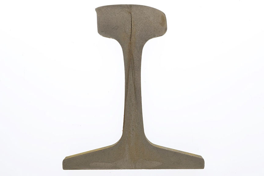

1.41 Predicted wheel impacts on rail end mismatch
Discontinuities between rail ends at a joint create dynamic wheel-rail forces that can result in wear, deterioration, and early failure of track components. The Volpe National Transportation Systems Center has modelled approaches of varying complexity to estimate the dynamic wheel-rail force (the wheel impact force) at joints with steps or transitions (or ramps) of various sizes.Footnote 56
The results of the Volpe study indicate that wheel impact force increases with increasing tread mismatch when a wheel encounters a step. For a given mismatch, the wheel impact force decreases as the ramp length increases. The wheel impact force also increases as speed increases, all other factors being constant. Representative examples of the predicted vertical wheel force response of a 286 000 pound GRL hopper car are shown in Table 5. The parameters used for the study were based on the maximum rail-end mismatch and speed permitted for each class of track defined by Title 49 of the Code of Federal Regulations, section 213.115 of the Federal Railroad Administration (FRA) Track Safety Standards. These classes of track are also consistent with the classes of track defined in the Track Safety Rules.(TSR).
| Case | Vertical rail-end mismatch (inch) | Ramp length (inch) | Speed (mph) |
Predicted dynamic vertical wheel force (kips) |
|---|---|---|---|---|
| 1 | 0.125 (3.2 mm) | 0 (step) | 60 | 69.4 |
| 2 | 0.1875 (4.8 mm) | 0 (step) | 40 | 83.7 |
| 3 | 0.25 (6.3 mm) | 0 (step) | 25 | 97.6 |
| 4 | 0.25 (6.3 mm) | 6 | 40 | 69.4 |
Each result represents a maximum safe combination of step height and speed. Therefore, a higher step height or shorter ramp length at a given speed (or a higher speed at a given mismatch condition) than those indicated in Table 5 would produce an unsafe wheel impact force condition.
In this occurrence, the speed was 43 mph and the joint likely had a vertical mismatch of between 3/16 inch (4.8 mm), which was the initial mismatch, and 0.265 inch (6.75 mm), which was the mismatch measured in the TSB Engineering Laboratory. A 2.5 inch (60 mm) ramp had been ground to ease the head height transition. Thus, the vertical mismatch was at some point between Case 2 and Case 4 from the Volpe study.
Based on the predicted wheel impact of 97.6 kips from Case 3 with a ramp length of 0 (step), wheel impact estimates were calculated for the derailment speed of 43 mph, for 50 mph, and for the maximum Class 4 track speed limit of 60 mph. Table 6 summarizes the results of these calculations.
| Vertical rail-end mismatch (inch) |
Ramp length (inch) | Speed (mph) | Estimated impact (kips) |
|---|---|---|---|
| 0.25 (6.3 mm) | 0 (step) | 25 | 97.6 |
| 0.25 (6.3 mm) | 0 (step) | 43 | 142.1 |
| 0.25 (6.3 mm) | 0 (step) | 50 | 159.5 |
| 0.25 (6.3 mm) | 0 (step) | 60 | 184.2 |
| 0.25 (6.3 mm) | 6 | 43 | 71.9 |
| 0.25 (6.3 mm) | 6 | 50 | 77.8 |
| 0.25 (6.3 mm) | 6 | 60 | 86.2 |
1.42 TSB testing of crude oil samples
Table 7 provides a summary of the shipping information on the transportation of DGs pertinent to the tank cars in the occurrence train.
| Tank car location in train | Shipping description under the Transportation of Dangerous Goods Act./th> | Information on safety data sheet | |||||
|---|---|---|---|---|---|---|---|
| Product identification number | Proper shipping name | Hazard class | Packing group | Product name | Synonyms | Manufacturer | |
| 1 to 94 | UN1267 | Petroleum crude oil | 3 | I | Horizon sweet light oil | Synthetic crude oil distillate; sweet light oil | Canadian Natural Resources Ltd., Calgary AB |
The material safety data sheet (MSDS) for Horizon sweet light oil describes the product as a complex mixture of hydrocarbons derived from primary distillation of petroleum crude oil with an initial boiling point of less than 35°C and a flash point of less than −20 °C.
Product samples (Figure 20) were taken from 2 representative non-derailed tank cars.Footnote 57
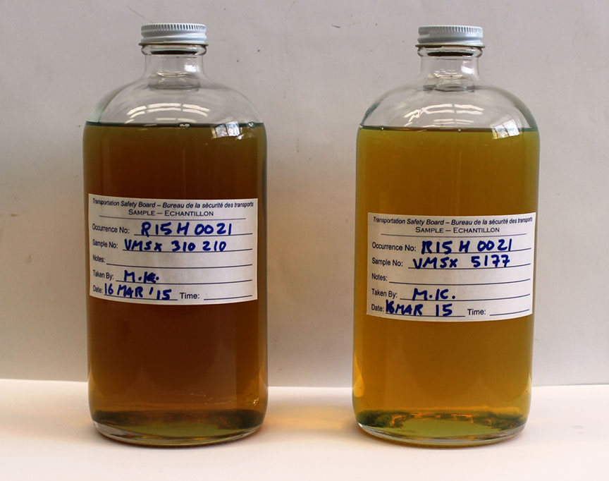
The samples were collected on 16 March 2015 at the Valero refinery in Lévis, Québec, under the direction of a TSB investigator. Prior to the collection of samples, the tank car hatches were opened and a gas test was performed in the work environment around the hatch of each car using a portable multi-gas detector able to detect 6 gases. The test results indicated that the work environment was adequate to work in without respiratory protection.
All crude oil samples were collected at atmospheric pressure. The samples were tested for characteristics relevant to the classification of the petroleum crude oil and to its behavior and effects during the post-accident spill and fire. The product samples were split and sent to 2 accredited external laboratories for testing. Table 8 lists the tests performed on each sample.
| Parameter | Test method | Laboratory |
|---|---|---|
| Flash point temperature | ASTM D3828-12a Standard Test Methods for Flash Point by Small Scale Closed Cup Tester - Method B | AITF |
| Boiling point distribution | ASTM D2887-14 Standard Test Method for Boiling Range Distribution of Petroleum Fractions by Gas Chromatography | AITF |
| ASTM D86-12 Standard Test Method for Distillation of Petroleum Products at Atmospheric Pressure | Maxxam | |
| Density | ASTM D5002-13 Standard Test Method for Density and Relative Density of Crude Oils by Digital Density Analyzer | Maxxam |
| Reid vapour pressure | ASTM D323-15a Standard Test Method for Vapour Pressure of Petroleum Products (Reid Method) | Maxxam |
| Sulphur content | ASTM D4294-10 Standard Test Method for Sulfur in Petroleum and Petroleum Products by Energy Dispersive X-ray Fluorescence Spectrometry | Maxxam |
| Viscosity | ASTM D7042-14 Standard Test Method for Dynamic Viscosity and Density of Liquids by Stabinger Viscometer (and the Calculation of Kinematic Viscosity) | Maxxam |
The test results for the occurrence product were compared to samples of similar products taken from tank cars at the Gladwick derailment (TSB Railway Investigation Report R13H0013), which occurred 3 weeks before this occurrence. Table 9 presents a comparative summary of the test results.
| Source | Product identifier | Total sulphur (mass %) | Reid vapour pressure (kPa) | Density (kg/m³) | Viscosity (cSt) at temperature | ||
|---|---|---|---|---|---|---|---|
| 20 °C | 30 °C | 40 °C | |||||
| Gogama derailment (R15H0021) | 22.3 to 22.4 | 0.094 | 24.6 to 24.7 | 847.8 to 848.8 | 18.42 to 18.75 | 6.010 to 6.100 | 3.580 to 3.626 |
| Gladwick derailment (R15H0013)* | 22.2 to 22.4 | 0.081 to 0.082 | 24.2 to 24.8 | 846.9 to 847.7 | 19.12 to 19.24 | 6.100 to 6.110 | 3.599 to 3.616 |
* TSB Engineering Laboratory report LP057/2015, Analysis of Crude Oil Samples, samples VMSX 310192 and VMSX 310187.
The product testing and comparisons revealed the following:
- The occurrence product samples had low density (847.8 to 848.8 kg/m³), low total sulphur (0.094 mass %), and low viscosity (3.580 to 3.626 cSt at 20 °C). These results were nearly identical to those obtained for the Horizon sweet light oil product samples analyzed for the Gladwick occurrence (R15H0013).
- The properties of the occurrence product were consistent with those of a light sweet synthetic crude oil distillate, with volatility generally comparable to that of the Bakken Shale crude oil involved in the Lac-Mégantic occurrence (R13D0054).
- The initial boiling points obtained for the occurrence product samples using the ASTM D2887 method were 22.3 °C to 22.4 °C. The occurrence product samples met the federal regulatory criteria for a Class 3 flammable liquid in PG I.
- The large quantities of spilled product and the properties of the spilled product (high volatility and low viscosity) contributed to the large post-derailment fire.
1.43 Tank car information
Historically, most legacy Class 111 tank cars were built with a GRL capacity of 263 000 pounds. In the mid-1990s, the industry began moving towards a Class 111 tank car with a GRL capacity of 286 000 pounds.
In the late 1990s, TC, the DOT, and the AAR established a number of requirements for tank car GRL to be increased to 286 000 pounds. The requirements included increased puncture resistance for the tank heads and shells, increased design loads, and enhanced protection of service equipment. These requirements were further incorporated into TC and AAR standards for tank cars with a GRL of 286 000 pounds. However, these requirements did not apply to the majority of Class 111 tank cars at the time, which had a GRL of 263 000 pounds. The next step was to address the cars with a GRL of 263 000 pounds.
In 2011, the AAR CPC-1232 tank car standards were established. These standards incorporated a number of enhancements to all Class 111 tank cars built after 01 October 2011 for the transportation of petroleum crude oil and ethanol (Class 3 PG I or PG II). These enhancements included the construction of tank cars to 286 000 pound standards, protection of the service equipment on the top shell, the use of reclosing pressure relief devices (PRD), the use of normalized steel for tank shells and tank heads, an increased minimum thickness for all tank cars that were not jacketed and insulated, and at least ½-inch thick half-head shields.
For Canada, the specifications applicable to tank cars built before December 2013 were listed in TC safety standard CAN/CGSB-43.147.Footnote 58 For tank cars built after December 2013, TC TDG tank specification TP14877 applied.Footnote 59 Other applicable specifications were Title 49 of the Code of Federal Regulations, paragraph 179.200Footnote 60 for the U.S., and the industry Casualty Prevention Circular No. CPC-1232 standard.Footnote 61
TC later incorporated these requirements into the Regulations Amending the Transportation of Dangerous Goods Regulations (TC 117 Tank Cars).which allowed Class 111 tank cars constructed to CPC-1232 requirements to be used in the interim for transporting flammable liquids until the TC-117 tank car became mandatory.
Following the Lac-Mégantic derailment (TSB Railway Investigation Report R13D0054), the rail industry believed that Class 111 tank cars constructed to the CPC-1232 standard would provide enhanced protection for Class 3 products compared to legacy Class 111 tank cars.Footnote 62
A GRL capacity of 286 000 pounds is not solely limited to tank cars. Most types of freight cars can be built to a 286 000 pound GRL capacity. Various types of freight cars with 286 000 GRL capacity have been in operation for over 30 years, with more being added each year. Unit trains for commodities other than crude oil such as coal, grain and potash had been operating during that same time period, primarily in western Canada. Many of the freight cars in this service had a 286 000 pound GRL capacity. However, crude oil unit trains were relatively new, particularly in eastern Canada, having come into operation primarily since 2010. Between 2010 and 2014, there was a 30% increase in traffic on the Ruel Subdivision and crude oil traffic accounted for 46% of this traffic increase.
Crude oil unit train tank cars are usually loaded to 286 000 pounds. In comparison, mixed merchandise and intermodal trains generally transport freight cars that have a lower GRL capacity. In 2014, the average crude oil unit train measured approximately 6000 feet long and weighed about 13 000 tons, which is considered a heavy train relative to its length. In comparison, a 13 000 ton mixed merchandise or intermodal train would typically range from about 9000 feet to 12 000 feet long.
Figure 21 identifies the primary components on a Class 111 (CPC-1232 compliant) tank car.
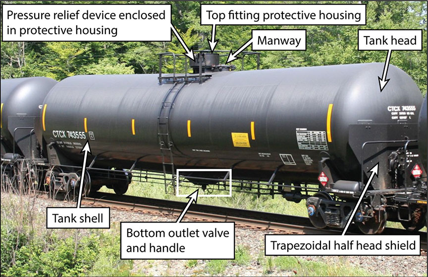
All 94 tank cars in the occurrence train were constructed for and owned by Valero, which was also the product shipper and consignee. The tank cars were loaded at the Pembina Redwater terminal facility in Redwater, Alberta, and were carrying product destined for Valero's refinery in Lévis, Quebec. All of the derailed tank cars were built within 3 years prior to the occurrence by Trinity Tank Car Inc., manufactured to U.S. DOT specification 111A100W1, and compliant with the industry's CPC-1232 standard.
The tank car heads and shells were made of AAR TC-128 Grade B normalized steel.Footnote 63 All head shields were constructed of ½-inch thick ASTM A572 Grade 50 steel plate. The 9th, 14th, 19th, and 29th derailed tank cars were equipped with full head shields, jackets, and insulation. The remaining tank cars were non-jacketed, non-insulated and equipped with trapezoidal half-head shields.
The tank cars were equipped with a 4-inch bottom outlet valve (BOV), top fittings (vacuum relief, 2-inch, and 3-inch ball valves) within a protective 20-inch multi-housing assembly, a hinged and bolted manway and a PRD. The PRD was fitted within the multi-housing assembly.
| Car location in train from head end* | Tank car number | Date certificate of construction approved | Head/shell thickness (inch) | Head shield | Jacket and insulation | Pressure relief device | |
|---|---|---|---|---|---|---|---|
| Start-to-discharge pressure (psig) |
Actual flow capacity** (scfm)*** | ||||||
| 6 | VMSX 310431 | Feb-2013 | 1/2 | Trapezoidal half shield | None | 75 | 27,000 |
| 7 | VMSX 310442 | Feb-2013 | 1/2 | Trapezoidal half shield | None | 75 | 27,000 |
| 8 | VMSX 311916 | Feb-2013 | 1/2 | Trapezoidal half shield | None | 75 | 27,000 |
| 9 | VMSX 280513 | Sep-2014 | 7/16 | Full shield | Steel jacket with 4-inch thick glass wool blanket | 165 | 2,329 |
| 10 | VMSX 310458 | Feb-2013 | 1/2 | Trapezoidal half shield | None | 75 | 27,000 |
| 11 | VMSX 310238 | Feb-2013 | 1/2 | Trapezoidal half shield | None | 165 | 35,608 |
| 12 | VMSX 310191 | Feb-2013 | 1/2 | Trapezoidal half shield | None | 165 | 35,608 |
| 13 | VMSX 310040 | Feb-2013 | 1/2 | Trapezoidal half shield | None | 165 | 35,608 |
| 14 | VMSX 5329 | Aug-2012 | 7/16 | Full shield | Steel jacket with 4-inch thick glass wool blanket | 165 | 2,329 |
| 15 | VMSX 310725 | Feb-2013 | 1/2 | Trapezoidal half shield | None | 75 | 27,000 |
| 16 | VMSX 311642 | Feb-2013 | 1/2 | Trapezoidal half shield | None | 75 | 27,000 |
| 17 | VMSX 310828 | Feb-2013 | 1/2 | Trapezoidal half shield | None | 75 | 27,000 |
| 18 | VMSX 310701 | Feb-2013 | 1/2 | Trapezoidal half shield | None | 75 | 27,000 |
| 19 | VMSX 280501 | Sep-2014 | 7/16 | Full shield | Steel jacket with 4-inch thick glass wool blanket | 165 | 2,329 |
| 20 | VMSX 310198 | Feb-2013 | 1/2 | Trapezoidal half shield | None | 165 | 35,608 |
| 21 | VMSX 310225 | Feb-2013 | 1/2 | Trapezoidal half shield | None | 165 | 35,608 |
| 22 | VMSX 310203 | Feb-2013 | 1/2 | Trapezoidal half shield | None | 165 | 35,608 |
| 23 | VMSX 310285 | Feb-2013 | 1/2 | Trapezoidal half shield | None | 75 | 27,000 |
| 24 | VMSX 311704 | Feb-2013 | 1/2 | Trapezoidal half shield | None | 75 | 27,000 |
| 25 | VMSX 311705 | Feb-2013 | 1/2 | Trapezoidal half shield | None | 75 | 27,000 |
| 26 | VMSX 311699 | Feb-2013 | 1/2 | Trapezoidal half shield | None | 75 | 27,000 |
| 27 | VMSX 311652 | Feb-2013 | 1/2 | Trapezoidal half shield | None | 75 | 27,000 |
| 28 | VMSX 310343 | Feb-2013 | 1/2 | Trapezoidal half shield | None | 75 | 27,000 |
| 29 | VMSX 28356 | Mar-2013 | 7/16 | Full shield | Steel jacket with 4-inch thick glass wool blanket | 165 | 2,329 |
| 30 | VMSX 310341 | Feb-2013 | 1/2 | Trapezoidal half shield | None | 75 | 27,000 |
| 31 | VMSX 310332 | Feb-2013 | 1/2 | Trapezoidal half shield | None | 75 | 27,000 |
| 32 | VMSX 311640 | Feb-2013 | 1/2 | Trapezoidal half shield | None | 75 | 27,000 |
| 33 | VMSX 310111 | Feb-2013 | 1/2 | Trapezoidal half shield | None | 165 | 35,608 |
| 34 | VMSX 310302 | Feb-2013 | 1/2 | Trapezoidal half shield | None | 75 | 27,000 |
| 35 | VMSX 310283 | Feb-2013 | 1/2 | Trapezoidal half shield | None | 75 | 27,000 |
| 36 | VMSX 310297 | Feb-2013 | 1/2 | Trapezoidal half shield | None | 75 | 27,000 |
| 37 | VMSX 310291 | Feb-2013 | 1/2 | Trapezoidal half shield | None | 75 | 27,000 |
| 38 | VMSX 310888 | Feb-2013 | 1/2 | Trapezoidal half shield | None | 75 | 27,000 |
| 39 | VMSX 311658 | Feb-2013 | 1/2 | Trapezoidal half shield | None | 75 | 27,000 |
| 40 | VMSX 310219 | Feb-2013 | 1/2 | Trapezoidal half shield | None | 165 | 35,608 |
| 41 | VMSX 311673 | Feb-2013 | 1/2 | Trapezoidal half shield | None | 75 | 27,000 |
| 42 | VMSX 311692 | Feb-2013 | 1/2 | Trapezoidal half shield | None | 75 | 27,000 |
| 43 | VMSX 310060 | Feb-2013 | 1/2 | Trapezoidal half shield | None | 165 | 35,608 |
| 44 | VMSX 311681 | Feb-2013 | 1/2 | Trapezoidal half shield | None | 75 | 27,000 |
* Throughout the report, tank cars are identified by their position in consist number.
** Note that the required flow capacity differs for non-insulated, insulated, or thermally protected tank cars.
*** Standard cubic feet per minute.
1.44 Site examination of derailed tank cars
Aerial photo-documentation of the derailment zone was performed before the post-derailment fire had been extinguished. Consequently, some of the derailment zone was obscured by smoke, which made it more difficult to document the site through aerial photographs. However, TSB investigators were able to examine the site and photograph most of the tank cars in situ while emergency responders dealt with the fire.
Once the fire was extinguished, the remaining product was removed from the tank cars. The tank cars were then moved to a staging area for cleaning and purging in preparation for site examination. The tank cars were examined by CN, the TSB, and representatives of the tank car manufacturer.
All of the derailed tank cars were in compliance with the specification requirement that was in effect at the time of their approval and construction. During the site examination, some test coupons of tank car material were collected from selected tank cars for metallurgical examination. The test coupons were sent to the TSB Engineering Laboratory for detailed examination.
1.44.1 Tank car breaches
A total of 39 tank cars had derailed. The 6th car and 44th car had no damage. These 2 cars were re-railed and pulled away from the site during remediation operations. Field examination of the derailed tank cars was conducted for the 7th car to the 43rd car.
Table 11 provides a summary of the type of breaches observed on the remaining 37 tank cars.
| Car location in train from head end | Reporting mark | Type of breach | |||||
|---|---|---|---|---|---|---|---|
| Head | Shell | Top fittings and pressure relief device | Manway | Bottom outlet valve | Thermal tear | ||
| 7 | VMSX 310442 | Breach | |||||
| 8 | VMSX 311916 | ||||||
| 9 | VMSX 280513 | ||||||
| 10 | VMSX 310458 | Breach | |||||
| 11 | VMSX 310238 | Breach | Breach | ||||
| 12 | VMSX 310191 | Breach | |||||
| 13 | VMSX 310040 | Breach | |||||
| 14 | VMSX 5329 | Breach | |||||
| 15 | VMSX 310725 | Breach | |||||
| 16 | VMSX 311642 | Breach | Breach | Breach | |||
| 17 | VMSX 310828 | Breach | |||||
| 18 | VMSX 310701 | Breach | |||||
| 19 | VMSX 280501 | Breach | Breach | Breach | |||
| 20 | VMSX 310198 | Breach | Breach | ||||
| 21 | VMSX 310225 | Breach | Breach | Breach | |||
| 22 | VMSX 310203 | Breach | Breach | Breach | |||
| 23 | VMSX 310285 | Breach | Breach | ||||
| 24 | VMSX 311704 | Breach | Breach | Breach | Breach | ||
| 25 | VMSX 311705 | Breach | Breach | ||||
| 26 | VMSX 311699 | Breach | |||||
| 27 | VMSX 311652 | Breach | |||||
| 28 | VMSX 310343 | Breach | |||||
| 29 | VMSX 28356 | ||||||
| 30 | VMSX 310341 | Breach | Breach | ||||
| 31 | VMSX 310332 | Breach | |||||
| 32 | VMSX 311640 | Breach | Breach | ||||
| 33 | VMSX 310111 | Breach | |||||
| 34 | VMSX 310302 | Breach | Breach | Breach | |||
| 35 | VMSX 310283 | Breach | |||||
| 36 | VMSX 310297 | Breach | |||||
| 37 | VMSX 310291 | Breach | Breach | Breach | |||
| 38 | VMSX 310888 | Breach | |||||
| 39 | VMSX 311658 | Breach | |||||
| 40 | VMSX 310219 | Breach | Breach | ||||
| 41 | VMSX 311673 | Breach | |||||
| 42 | VMSX 311692 | Breach | |||||
| 43 | VMSX 310060 | ||||||
With regard to tank car breaches, the following observations were made:
- Thirty-three (33) of the 39 derailed tank cars (85%) were breached and released various amounts of product.
- Fourteen (14) of the breached tank cars sustained more than 1 type of breach.
- Nineteen (19) of the 33 breached tank cars (58%) lost their entire load due to fire and/or spillage.
- Fourteen (14) of the 33 breached tank cars (42%) lost part of their load. The remaining product was transferred during remediation operations.
- One (1) of the tank cars (the 24th car) had separated completely into 2 portions.
- Release from smaller breaches, while not instantaneous, helped feed the pool fire and contributed to spillage of product after the fire was extinguished.
1.44.2 Damage to tank car shell
The field examination determined the following:
- The 7th and 43rd tank cars had no visible impact-related shell deformation, denting, or scoring. The other 35 of the 37 cars examined exhibited some form of shell collision damage. The shell damage ranged from minor dents and scratches to larger dents and gouges. About 10 tank cars located in the area of the main pileup exhibited large-scale transverse buckling and crushing, which is indicative of plastic collapse.
- The shells of 13 tank cars were breached from impact damage. Four tank cars (the 14th, 19th, 21st, and 42nd cars) had small punctures less than 1 foot in diameter. Nine tank cars had larger shell breaches, with dimensions ranging from a few feet to the length of a shell ring. The majority of shell breaches were punctures consistent with collisions with sharp smaller objects (e.g., couplers, trucks, bolsters), while a few tank cars exhibited fractures at sharp folds or buckles in the shell material.
- The 24th tank car shell fractured circumferentially and broke into 2 portions. Since this tank car came to rest underneath other tank cars within the main pileup, it likely experienced more severe collision conditions in comparison to those cars located in the front or in the rear of the derailment zone.
- All of the shell breaches exhibited features that were typical of ductile overstress failure (slanted fracture surfaces, plastic deformation, and rough fibrous appearance). There was no indication of brittle failure.
- The 4 tank cars equipped with a steel jacket and insulation (the 9th, 14th, 19th, and 29th cars) exhibited various degrees of shell impact damage. Two tank cars (the 9th and 29th cars) had relatively minor jacket deformation with no shell breach, while the other 2 tank cars (the 14th and 19th cars) had extensively deformed and torn jackets and shell punctures. The 2 tank cars with shell punctures came to rest in a portion of the pileup where the jackknifed tank cars were tightly packed. These tank cars likely experienced more severe collision conditions than those located in front of the derailment (such as the 9th car) or in a less densely packed portion of the pileup (such as the 29th car).
The location in which the tank cars with shell impact breaches came to rest is shown in Appendix D.
1.44.3 Thermal damage
Thermal damage occurs when a tank car is exposed to a post-derailment fire. Heat-induced (thermal) tears usually occur in loaded tank cars when they are exposed to a fire and the PRD or other tank breaches are unable to vent the rising internal pressure. This can result in an energetic rupture of the tank. When Class 3 flammable liquids are involved, the sudden release of the pent-up pressure usually results in the loss of lading as a large fireball and subsequent fire within the tank that often burns off remaining product to atmosphere. Tank ruptures caused by overheating generally fracture longitudinally along an axis which is perpendicular to the hoop stress in the tank shell.
Most of the 37 tank cars examined by the TSB exhibited damage indicating that they had been exposed to the post-derailment fire. The fire damage ranged from scorched paint to changes in surface carbon content and external oxidation consistent with exposure to crude oil and air at elevated temperature.
The examination determined the following:
- Fifteen (15) tank cars sustained breaches due to thermal tears resulting from exposure to post-derailment fires.
- Ten (10) of the 15 tank cars with thermal tears had no other breaches that might have contributed to the release of internal pressure.
- Of the 5 remaining tank cars with thermal tears,
- 3 had BOV breaches,
- 1 had a head breach, and
- 1 had a head breach and a BOV breach.
- When the location of the thermal tears was compared to the car orientation after it came to rest, every thermal tear was situated in the vapour space of the tank.
- Metallurgical examination of a coupon containing a thermal tear revealed features such as necking, a fibrous fracture surface, and elongated micro-voids adjacent to the fracture surface that were consistent with ductile failure at high temperature.
- The thermal tears ranged from 18 inches to 240 inches long. In most cases, the plate material had significant thinning in the bulged areas around the thermal tears. Measurements of the lip thickness gave reduction-in-thicknessFootnote 64 ranging from 17% to 70%. These results are generally consistent with the reduction-in-thickness values observed in a previous derailment involving CPC-1232 tank carsFootnote 65 and with published tensile ductility results for AAR TC128 Grade B steel tested at elevated temperature.Footnote 66
- All tank cars with thermal tears were exposed to the large post-derailment fire fed by the tanks cars with shell and/or head impact breaches.
It has been suggested that PRDs with higher start-to-discharge pressure might be at risk of building up excessive internal pressure during a fire, resulting in more energetic (larger) thermal tears. With regard to PRDs and thermal tears, the following observations were made:
- All 15 tank cars with thermal tears were equipped with PRDs providing an actual flow capacity greater than 27 000 standard cubic feet per minute.
- 4 of the tank cars with thermal tears (the 11th, 12th, 13th, and 40th cars) had a PRD with a start-to-discharge pressure of 165 psig, while the other 11 tank cars with thermal tears had 75 psig PRDs.
- On the 4 tank cars equipped with a 165 psig PRD, thermal tear length ranged from 22 inches to 96 inches long.
- On the 11 tank cars equipped with a 75 psig PRD, thermal tear length ranged from 18 inches to 240 inches long.
There was no indication that tank cars equipped with higher start-to-discharge PRDs had experienced more energetic (larger) thermal tears in this occurrence.
With regard to the 4 jacketed and insulated tank cars that were exposed to the post-derailment fire:
- Two (2) of the tank cars (the 14th and 19th cars) were breached from impact. These breaches would have contributed to relieving any increase in pressure caused by exposure to the post-derailment fire, making the tank car less susceptible to thermal tear failure.
- The 2 other cars (the 9th and 29th cars) had no impact breaches and did not sustain thermal tears.
- The 29th tank car was close to several impact-breached tank cars and was fully exposed to the post-derailment fire.
- The 9th tank car came to rest partially submerged in the Makami River. This may have had a cooling effect that slowed the rise of internal pressure in the tank car while it was exposed to the post-derailment fire.
The small number of jacketed cars involved in this occurrence and the varying conditions experienced by each of these cars meant that it was not possible to determine whether the jacket and insulation made the tank car less susceptible to thermal tear failure.
Burn-throughs (perforations caused by fire damage) occur when the tank car material is exposed to crude oil and air at elevated temperatures during the post-derailment fire. The resulting material degradation processes, high-temperature carburization and oxidation, are responsible for steel plate erosion and loss of material, which can cause a burn-through. In this occurrence,
- Five (5) shell breaches (in the 16th, 18th, 20th, 21st, and 23rd cars) had jagged edges with red discolouration and visibly reduced tank shell wall thickness, indicative of a burn-through.
- Two (2) tank car head breaches (the 25th and 26th cars) exhibited features that corresponded to burn-throughs.
- All of the cars with burn-throughs were located in the main pileup.
- It is considered likely that loss of material from fire damage caused some shell and head impact breaches to grow larger.
The location in which the tank cars with thermal tear breaches came to rest is shown in Appendix E.
1.44.4 Damage to head shield and tank head
The CPC-1232 standard requires that non-jacketed tanks be equipped with half-head shields whereas jacketed tanks must be equipped with ½ inch thick jacket heads. Requirements for tank-head puncture-resistance systems are specified in the U.S. Code of Federal Regulations.Title 49, Part 179,Footnote 67 and in the AAR Specifications for Tank Cars.Footnote 68 These requirements include design conditions and performance testing for system survivability after coupler-to-tank-head impacts at relative speeds of 29 km/h (18 mph).
Of the 37 derailed tank cars examined by the TSB:
- 37 (100%) had some form of collision damage to their head shields.
- 15 (41%) were missing one head shield and 2 (5%) tank cars had lost both. Most head shields separated due to broken attachment brackets.
- 26 (70%) exhibited impact damage in one or both tank heads.
- 7 (27%) had sustained a breached head due to impact damage. Most of the 7 head breaches were punctures or tears with dimensions ranging from a few inches to about 2 feet.
- On 2 of the tank cars (the 16th and 20th cars), the head was breached above the half-head shield.
- On 3 tank cars (the 22nd, 30th, and 37th cars), the half-head shield was missing and the breach was in the bottom portion of the head. All head breaches were associated with significant deformation suggesting that the heads had been subjected to large collision forces.
- On 1 car (the 26th car) the B-end half-head shield and most of the B-end head were missing. It is considered most probable that this head breach would have caused the rapid release of the tank car's lading.
- All of the head breaches exhibited features that were typical of ductile overstress failure (slanted fracture surfaces, plastic deformation, and rough fibrous appearance). There was no sign of brittle failure.
- The 4 tank cars equipped with jackets, insulation and full head shields (the 9th, 14th, 19th, and 29th cars) exhibited various degrees of impact damage but were not breached.
The examination results indicate that the full head shields fitted on the CPC-1232 tank cars were most effective in protecting the tank heads against impact punctures during the derailment. The location in which the tank cars with head impact breaches came to rest is shown in Appendix F.
1.44.5 Damage to top fittings and pressure relief devices
All of the 39 derailed tank cars were fitted with protective housings designed in accordance with the AAR's top protection requirements for non-pressure cars.
The protective housing on 18 of the 39 derailed tank cars (46%) had some form of impact damage. In most cases the impact damage was relatively minor. However, 4 tank cars exhibited extensive impact damage to their protective housing, as follows:
- On the 17th and 30th cars, the wall of protective housing was deformed and the housing was partially separated from the top fitting nozzle cover.
- On the 16th and 24th cars, the protective housing was completely separated from the top fitting nozzle cover. All of the top fittings of these 2 tank cars were sheared off.
The protective housing and top fittings of several tank cars exhibited extensive red discolouration from fire damage. The caps of some fittings were made of a material that melted during the post-derailment fire, leaving the ball of the fitting exposed.
1.44.6 Damage to manways
The derailed cars were equipped with hinged and bolted manway covers. On 20 of the 37 derailed tank cars examined by the TSB, the manway cover had been opened during remediation operations. The manway covers of 11 tank cars were closed. For the remaining 6 tank cars,
- One of the eyebolts on the 41st car was dislodged and product residue was observed, indicating that the seal had been compromised.
- Five (5) of the tank cars were breached from an impact-damaged manway:
- The manway covers of 3 tank cars (the 17th, 21st, and 34th cars) were missing.
- On the 19th tank car, the manway nozzle was extensively deformed and the manway cover was broken.
- The 24th tank car had separated into 2 portions, and the fracture went through the manway nozzle and manway reinforcing pad.
1.44.7 Damage to skid protection and bottom outlet valves
The BOV skid protection on 28 of the 37 tank cars examined sustained some form of impact damage, ranging from deformation or crushing of the skid assembly to a broken skid and/or separated skid-to-shell weld. Most tank cars with damaged skids also had significant shell deformation in the vicinity of the skid, indicating that they had been subjected to large collision forces. The BOV damage observed on the 37 derailed tank cars examined is summarized in Table 12.
| Skid | Handle assembly | BOV adaptor | |||
|---|---|---|---|---|---|
| Condition | No. of cars affected | Condition | No. of cars affected | Condition | No. of cars affected |
| No impact damage | 6 | No impact damage | 6 | No impact damage | 13** |
| Impact damaged | 28 | Deformed or missing | 28 | Sheared off, exposing BOV ball | 20 |
| Unknown* | 3 | Unknown* | 3 | Unknown* | 3 |
* Unknown because this portion of the tank car was not visible for inspection.
** The cap of the BOV adaptor of the 15th tank car was broken, but there was no indication of product loss.
The AAR requires that "bottom outlet valve handles, unless stowed separately, […] be designed to either bend or break free on impact, or the handle in the closed position must be located above the bottom surface of the skid."Footnote 69 In this occurrence, the BOV handle assembly and securement mechanism of 28 tank cars had some form of impact damage, ranging from impact-related deformation to complete separation of the handle assembly and securement mechanism.
The BOV adaptor was sheared off at the mounting flange (the intended breaking point) on 20 of the tank cars, which caused their BOV ball to be exposed. With the exception of the 31st and 41st cars, these cars also had impact-damaged or missing BOV handles.
Of the 20 tank cars with sheared-off BOV adaptors, 13 tank cars (65%) (the 7th, 11th, 19th, 21st, 22nd, 23rd, 24th, 31st, 32nd, 33rd, 34th, 37th, and 40th cars) had an open, partially open, or visibly leaking BOV ball. All of the tank cars with breached BOVs had an impact-damaged handle assembly.
The location in which the tank cars with BOV breaches came to rest is shown in Appendix G.
The investigation into a 2013 derailment involving pre-CPC-1232 Class 111 tank cars in Ontario (TSB Railway Investigation Report R13T0060) had previously identified this issue. TSB Rail Safety Advisory 15/13 was issued to Transport Canada to communicate the risk of product loss through BOV handles that are damaged during derailments. This risk was also identified during the Lac-Mégantic investigation.
1.44.7.1 National Transportation Safety Board recommendation regarding bottom outlet valves
Following an investigation into the 2009 derailment of a CN freight train in Cherry Valley, Illinois, the NTSB determined that "existing standards and regulations for the protection of bottom outlet valves on tank cars do not address the valves' operating mechanisms and therefore are insufficient to ensure that the valves remain closed during accidents."Footnote 70 The NTSB recommended that the Pipeline and Hazardous Materials Safety Administration (PHMSA)
Footnote 71In 2016, PHMSA HM-251 required bottom outlet valve protection for the DOT-117 tank car, including performance and retrofit standards, in sections 179.202-8, 179.202-12(e), and 179.202-13(g) of the U.S. Code of Federal Regulations.Title 49, Part 179. Specifically, all bottom outlet handles must either be removed or designed to prevent unintended actuation during derailment scenarios. These provisions satisfied the intent of NTSB Safety Recommendation R-12-6, which was subsequently classified as CLOSED—ACCEPTABLE ACTION.
1.44.8 Damage to stub sills
Tank car stub sills are prohibited from being attached directly to the tank shell. The AAR requires that reinforcement pads be attached to the tank shell and that the stub sills be attached to the reinforcement pads. The AAR also requires that the reinforcement plate be extended on either side of the sill attachment and at the head brace attachment.Footnote 72Footnote 73 These requirements are intended to prevent product release by ensuring that, if a stub sill is overloaded, the separation occurs between the sill and the reinforcement pad, and does not propagate into the tank shell.
Thirty-one (31) of the 37 tank cars examined had sustained impact damage to at least one stub sill and/or coupler assembly, and 25 tank cars were damaged on both ends.
While 6 of the tank cars (the 15th, 16th, 23rd, 25th, 37th, and 39th cars) separated at the stub sill attachment, none of the stub sill attachment separations caused a tank breach.
1.44.8.1 Tank car material
The tank car head and shell material met the requirements for chemical composition and tensile properties of the specified AAR TC128 Grade B normalized steel.
1.45 Legacy Class 111 and Class 111 CPC-1232 compliant tank cars
A TSB case study was conducted into 3 accidents that involved the derailment of Class 111 tank cars carrying crude oil. In each case, the breached tank cars ignited a large pool fire. The relevant accident information is summarized in Table 13.
| TSB occurrence number | |||
|---|---|---|---|
| R13D0054 | R15H0013 | R15H0021 | |
| Accident summary | Runaway and main-track derailment, Montreal, Maine & Atlantic Railway, Freight train MMA-002, Mile 0.23, Sherbrooke Subdivision, Lac-Mégantic, Quebec | Main-track derailment, Canadian National Railway Company, Unit train U70451-10, Mile 111.6, Ruel Subdivision, Gladwick, Ontario | Main-track derailment, Canadian National Railway Company, Unit train U70451-02, Mile 88, Ruel Subdivision, Gogama, Ontario |
| Date of accident | 06 July 2013 | 14 February 2015 | 07 March 2015 |
| Lading | Petroleum crude oil (UN1267) | Petroleum crude oil (UN1267) and Petroleum distillates (UN1268) | Petroleum crude oil (UN1267) |
| Number of tank cars in consist | 72 | 100 | 94 |
| Location in train of first tank car to derail | 3 | 7 | 6 |
| Number of tank cars derailed | 63 | 29 | 39 |
| Speed at derailment | 65 mph (105 km/h) | 38 mph (61 km/h) | 43 mph (69 km/h) |
| Temperature reported at time of derailment | 21 °C | −30 °C | −9 °C |
Several types of Class 111 tank cars are used for transporting flammable liquids. These include jacketed and insulated tank cars as well as non-jacketed and non-insulated tank cars. Legacy Class 111 tank cars are those that were ordered prior to 01 October 2011 and built to older TC/DOT 111 standards. CPC-1232 compliant Class 111 tank cars were built since 2011 and meet the TP14877Footnote 74/CPC 1232Footnote 75 standard. Tank cars manufactured on or after 01 October 2015 must meet the new TC/DOT 117 standard. The different features of these three standards are summarized in Table 14.
| Requirements | Older legacy Class 111 | Class 111 CPC-1232 compliant | New TC/DOT- 117* | |
|---|---|---|---|---|
| Non-jacketed and non-insulated | Jacketed and insulated | |||
| Head shields | No | Half | Full | Full |
| Top-fitting protection | Optional | Mandatory | Mandatory | Mandatory |
| Thermal protection and jacketed | Optional | Optional | Optional | Mandatory |
| Normalized steel | Optional | Mandatory | Mandatory | Mandatory |
| Thickness and type of steel (minimum) | 11.1 mm (7/16 inch) | 12.7 mm (1/2 inch) thick TC128-B or 15.9 mm (5/8 inch) in ASTM A516-70 |
11.1 mm (7/16 inch) thick TC128-B or 12.7 mm (1/2 inch) in ASTM A516-70 |
14.3 mm (9/16 inch) thick in TC128-B |
| Performance standard for thermal protection, head and shell puncture resistance | No | No | No | Yes |
| Enhanced performance standard for bottom outlet valves | No | No | No | Yes |
* Regulations Amending the Transportation of Dangerous Goods Regulations.(TC 117 Tank Cars), P.C. 2015-486, 30 April 2015, SOR/2015-100, Canada Gazette, Part II, Vol. 149, No. 10, 20 May 2015, available at http://gazette.gc.ca/rp-pr/p2/2015/2015-05-20/html/sor-dors100-eng.php (last accessed on 06 June 2017).
Tank car damage is strongly influenced by the derailment speed and number of tank cars involved in a derailment. In this case study, occurrence R15H0013 (Gladwick) had the lowest incidence of breached tank cars (66%), the lowest derailment speed, and lowest number of derailed tank cars. The percentage of tank cars with more than one type of breach increased with an increase in derailment speed and/or number of derailed cars.
The percentage of cars with any type of breach in occurrence R15H0021 (Gogama) was similar to that observed in occurrence R13D0054 (Lac-Mégantic), which involved significantly higher speed and a higher number of derailed cars. An overview of the tank car damage observed during the subject occurrences is contained in Table 15.
| Condition | Cars affected in R13D0054 | Cars affected in R15H0013 | Cars affected in R15H0021 | |||
|---|---|---|---|---|---|---|
| Number | Percentage | Number | Percentage | Number | Percentage | |
| Derailed | 63 | - | 29 | - | 39 | - |
| No breach observed | 4 | 6 | 10 | 34 | 6 | 15 |
| Breached (any type) | 59 | 94 | 19 | 66 | 33 | 85 |
| More than one type of breach | 33 | 52 | 6 | 21 | 14 | 36 |
The legacy Class 111 tank cars involved in occurrence R13D0054 had the highest percentage of shell, head, top fitting, and PRD breaches. For the Class 111 CPC-1232 compliant tank cars involved in occurrence R15H0013, shell breaches had the highest incidence, followed by thermal tears. For the Class 111 CPC-1232 tank cars involved in occurrence R15H0021, thermal tears were the most frequent breach, followed by an equal number of shell and BOV breaches.
A summary of the various types of breach responsible for product release during the subject occurrences is contained in Figure 22.Footnote 76

When tank car performance from the 3 accidents was compared, the following general observations were made:
- Occurrences R15H0013 and R15H0021, which involved Class 111 CPC-1232 compliant tank cars, had a similar incidence of shell breaches (about one-third of the derailed tank cars). The incidence of shell breaches was almost doubled (59%) for occurrence R13D0054, which involved legacy Class 111 tank cars.
- In occurrence R13D0054, about half of the tank cars with large shell ruptures were clustered towards the end of the train and formed a large pileup. This large pileup likely acted like a wall that resulted in highly constrained derailment conditions. This caused large-scale buckling and extreme tank deformations and structural failure of the legacy tank cars due to plastic collapse.
- Occurrences R15H0013 and R15H0021 produced pileups in which some tank cars were buried under, and others projected over, adjacent cars. These collisions generated forces of sufficient magnitude to split 4 tank cars into 2 portions.
- In all cases, the majority of the shell breaches (69% to 89%) were of medium to large size (from about 1 foot to the circumference of the car). These large shell breaches likely caused the rapid release of the tank car's lading and were factors which contribute to the large pool fires.
The TSB case study determined that:
- For the legacy Class 111 tank cars involved in occurrence R13D0054, the most frequently observed types of breach were shell breaches, followed by head breaches. For the Class 111 CPC-1232 compliant tank cars involved in occurrence R15H0013, shell breaches had the highest incidence, followed by thermal tears. For the Class 111 CPC-1232 compliant tank cars involved in occurrence R15H0021, thermal tears were the most frequent breach, followed by an equal incidence of shell and BOV breaches.
- Even though the cars were constructed of normalized steel, brittle shell fractures were observed on some Class 111 CPC-1232 compliant tank cars involved in occurrence R15H0013. This indicates that a non-jacketed and non-insulated Class 111 CPC-1232 compliant tank car may experience brittle shell fracture when subjected to the combined effects of low ambient temperature and severe collision conditions. Similarly, it is likely that legacy Class 111 tank cars constructed of non-normalized material would be even more vulnerable to brittle shell fracture when subjected to the same conditions.
- Of the 6 jacketed and insulated Class 111 CPC-1232 compliant tank cars involved in the R15H0013 and R15H0021 derailments, 3 were breached from a shell puncture. This suggests that the additional impact resistance afforded by the jacket was insufficient for the collision conditions during these derailments.
- The Class 111 CPC-1232 compliant tank cars had a significantly lower incidence of head breaches than the legacy Class 111 tank cars. However, the case study suggests that full-head shields are more effective than half-head shields when severe collision conditions are involved.
- The legacy Class 111 cars and Class 111 CPC-1232 compliant tank cars with top protection had a significantly lower incidence of breached top fittings and PRDs than the legacy Class 111 tank cars that did not have top protection.
- The incidence of product loss from impact-damaged BOVs was similar for both legacy Class 111 and Class 111 CPC-1232 compliant tank cars. Some of these cars might not have experienced product loss had they been equipped with a handle assembly configured to prevent unintended actuation of the ball valve.
- The case study suggests that the risk of failure due to a thermal tear is of similar magnitude for non-jacketed and non-insulated legacy Class 111 tank cars as well as non-jacketed and non-insulated Class 111 CPC-1232 compliant tank cars.
- There was insufficient information to determine whether jacketed and insulated Class 111 CPC-1232 tank cars have enhanced fire survivability.
- The non-jacketed and non-insulated Class 111 CPC-1232 compliant tank cars and legacy Class 111 tank cars examined for occurrence R13D0054 appear to have similar performance when subjected to severe derailment conditions such as those present in the subject occurrences.
1.46 TSB Watchlist
The TSB Watchlist identifies the key safety issues that need to be addressed to make Canada's transportation system even safer.
Safety management and oversight will remain on the TSB Watchlist until
- Transport Canada implements regulations requiring all commercial operators in the air and marine industries to have formal safety management processes and effectively oversees these processes;
- transportation companies that do have SMS demonstrate that it is working—that hazards are being identified and effective risk-mitigation measures are being implemented; and
- Transport Canada not only intervenes when companies are unable to manage safety effectively, but does so in a way that succeeds in changing unsafe operating practices.
1.46.1 Safety management and oversight
Transportation companies have a responsibility to manage safety risks in their operations. SMS provides a framework to achieve this end, and many companies implement a formal SMS either voluntarily or to comply with TC's SMS Regulations. Even small companies need to have some safety processes in place to manage risk.
Some companies consider safety to be adequate as long as they are in compliance with regulatory requirements, but regulations alone cannot foresee all risks unique to a particular operation. That is why the TSB has repeatedly emphasized the advantages of SMS, an internationally recognized framework to allow companies to effectively manage risk and make operations safer.
The move toward an SMS regime must be supported by appropriate regulatory oversight. Given that regulators will encounter companies with varying degrees of ability or commitment to effectively manage risk, this oversight must be balanced. It needs to include proactive auditing of companies' safety management processes, ongoing education and training, and traditional inspections to ensure compliance with existing regulations.
Moving forward, 3 elements are key: a clear regulatory framework requiring companies to implement some form of SMS; SMS that are effective in identifying hazards and mitigating risks; and balanced regulatory oversight.
Previous TSB investigations have revealed some problems:
- Although all rail operators in Canada are required to have an SMS, the TSB has identified instances where SMS processes were weak or not used, resulting in hazards going unidentified and risk mitigations not being put in place.Footnote 77
- With respect to TC regulatory oversight, 2 problems have been observed: a failure to identify companies' ineffective processes, and an imbalance between auditing processes versus traditional inspections.
1.46.2 Transportation of flammable liquids by rail
Transportation of flammable liquids by rail will remain on the Watchlist until
- railway companies conduct thorough route planning and analysis, and perform risk assessments to ensure that risk-control measures are effective; and
- more robust tank cars are used when large quantities of flammable liquids are transported by rail to reduce the likelihood of a dangerous-goods release during accidents.
In November 2014, the TSB added "Transportation of flammable liquids by rail" to its Watchlist issues. This issue remained on TSB's Watchlist in 2016.
The transportation of crude oil by rail across North America increased exponentially starting in 2009, peaking in 2014 at 238 000 carloads in CanadaFootnote 78 and 500 000 carloads in the U.S.Footnote 79 Ethanol shipments, meanwhile, were relatively stable, with an average of 76 250 carloads per year in Canada and 331 000 carloads per year in the U.S.Footnote 80 Despite recent downward trends, the volume of flammable liquids being transported by rail is expected to remain significant.
The TSB is concerned that current railway operating practices, combined with the vulnerability of older tank cars used to transport crude oil and other flammable liquids, are not adequate to mitigate effectively the risk posed by the transportation of large quantities of such dangerous goods by rail.
The vulnerability of Class 111 tank cars has been recognized for years.Footnote 81 The Board has called for tougher standards for all Class 111 tank carsFootnote 82—not just new ones—to reduce the likelihood of product being released during accidents. A number of accidents investigated in the U.S. by the NTSB have also highlighted the vulnerability of Class 111 tank cars.Footnote 83
The TSB is encouraged that federal regulators in Canada and the U.S. have taken considerable action to address the situation, including the promulgation of a more robust tank car standard (Class 117), retrofit provisions, implementation timelines, and regulatory monitoring and enforcement. The actions to date by the federal regulators and the railway industry have contributed to a significant decline in the use of legacy Class 111 tank cars to transport crude oil since 2014.
Although the federal regulators and the railway industry have taken actions with respect to tank car safety, federal regulations nonetheless allow Class 111 tank cars to be used for the transport of certain flammable liquids until mid-2025. Consequently, until all higher-risk flammable liquids in North America are transported in more robust tank cars with enhanced protection, an elevated risk will remain.
Since the Lac-Mégantic derailment in July 2013 (TSB Railway Investigation Report R13D0054), other recent derailments in CanadaFootnote 84 have demonstrated that there can be significant risk to people, property, and the environment when trains carrying large volumes of flammable liquids derail.
These recent occurrences highlight the need for strategic route planning and safer operations of all trains carrying DGs in Canada. Railways must carefully choose the routes on which crude oil and other flammable liquids are to be carried, and ensure that train operations over those routes will be safe. These risks must be dealt with as a North American transportation issue, because these products are transported across borders by rail operators.
1.47 TSB laboratory reports
The following TSB laboratory reports in support of this investigation:
- LP 052/2015 – Examination of tank cars (R15H0021)
- LP 053/2015 – Analysis of crude oil samples (R15H0021)
- LP 054/2015 – Examination of rail joint and pieces (R15H0021)
- LP 84/2015 - Rail Failure Examination (R15H0020)
- LP051/2016 - Case study of derailment damage: Legacy versus enhanced Class 111 tank cars (R13D0054, R15H0013, and R15H0021)
2.0 Analysis
The train was operated in accordance with company and regulatory requirements. The rolling stock was maintained in good condition, and there were no defects observed that were considered as being contributory to this occurrence. The analysis will focus on the rail failure, Canadian National Railway Company (CN) maintenance practices with regard to the installation of plug rails, training of track maintenance personnel, tank car performance, crude oil properties, speed of key trains, CN's safety management system (SMS) and corridor risk assessment, CN's incident command and emergency response, regulatory oversight, and environmental impact.
2.1 The accident
On 07 March 2015, at about 0242, CN crude oil unit train U70451-02 was proceeding eastward at about 43 mph on CN's Ruel Subdivision when a train-initiated emergency brake application occurred at Mile 88.70 near Gogama, Ontario. The 6th to the 44th car (39 cars in total) had derailed. As a result of the derailment, about 2.6 million litres of petroleum crude oil (UN1267) was released to atmosphere, water, or surface. The released product ignited and caused explosions, and some product entered the nearby Makami River. About 1000 feet of track was destroyed, and the ensuing fires destroyed the CN railway bridge that traversed the river.
Approaching the derailment site from the west, there were no impact marks observed on the track infrastructure. At the west end of the derailment site, a number of broken pieces of the south rail were recovered in the vicinity of Mile 88.75 including
- a 146-inch-long section of rail containing a broken thermite weld that had been removed from the south rail and replaced with a plug rail of equal length 3 days before the derailment;
- the east joint of a plug rail, with joint bars securing a 53-inch-long section and a fractured 20-inch-long section of the east end parent rail; and
- a 4-inch-long piece of the rail head from the fractured 20-inch-long section of the east end parent rail. The recovered piece of the rail head exhibited a vertical split head (VSH) rail defect.
The east end parent rail had an area of horizontal web fracture between the joint bars and a web/base fracture east of the joint bar ends. The web fracture surface displayed pounding damage that indicated that this fracture occurred prior to the final rail failure and had remained in track for some time before the occurrence. The 4-inch-long recovered section that contained the VSH defect mated with the horizontal web fracture.
Prior to the arrival of the train, a 16-inch-long portion of the parent south rail head had broken off due to a VSH rail failure within the east joint of a plug rail repair, leaving a gap in the south rail. The derailment occurred when the south rail failed catastrophically beneath the train as it traversed the track, resulting in the derailment of the 6th to 44th tank cars, which were loaded with petroleum crude oil.
2.2 Plug rail repair
Three days before the derailment, the signals controlling traffic into the Gogama-Bethnal block (Mile 86.20 to Mile 94.70) unexpectedly changed to a RED indication at about 1935, prohibiting rail traffic from entering the block. Because the regular track maintenance foreman (TMF) had been called out to replace a defective rail east of Gogama, the track supervisor (TSPVR) instructed the snow patrol foreman (SPF), who was also a thermite welding foreman during the summer, and a helper on light duties, to find the source of the outage. About 1½ hours later, a broken thermite weld was located in the south rail at Mile 88.75.
2.2.1 Dye penetrant testing
Since the section work crew was at the end of its shift and nearing the end of available hours to operate the track force optimization (TFO) vehicle, the TSPVR asked the SPF and the helper to change out the rail. After arriving on site with the required materials, the SPF prepared for the installation of the plug rail. During the plug rail repair, the parent rail was cut and the exposed rail ends were visually inspected for cracks. No defects were noted. However, the SPF did not perform a dye penetrant test on the cut rail ends as required by the CN Engineering Track Standards.(ETS), section 1.7.
TSB examination of the original break at the thermite weld on the east end of the parent rail revealed a VSH defect in the rail head similar to the VSH defect observed in the east end joint parent rail. The VSH defect had propagated through the thermite weld from the original east parent rail to the west parent rail before the original rail break and plug rail repair. This suggests that a VSH defect had been present in the east parent rail but not identified during the plug rail repair. Had a dye penetrant inspection been performed, a VSH indication would likely have been observed in the cut east rail end, and more of the east parent rail may have had to be removed.
2.2.2 Rail grinding
The plug rail was rolled into track with no joint gaps, the joint bolt holes were drilled, and the plug rail was bolted, spiked, and anchored in place. After the repair, the plug rail was higher than the parent rail at the east end of the installation. Although no physical measurements were taken, the SPF visually estimated that the plug rail was 2 mm higher than the parent rail, which was an underestimate.
A mismatch of only 2 mm is less than the 3 mm allowed for Class 4 track and would not have required any grinding to ensure a smooth transition between the rails. Nevertheless, the SPF decided to touch up the mismatch by grinding 2.5 inches (60 mm) of the east plug rail head with a hand grinder to make a short ramp between the running surfaces of the plug rail and the parent rail. The hand grinder was used because the larger rail grinder was not available.
The overall mismatch on the occurrence rails was in the range of 0.375 inch (9 mm). Although rail end batter (REB) and post-fracture pounding on the horizontal web fracture contributed to the mismatch, the actual mismatch was likely about 0.265 inches (6.75 mm). Had a similar mismatch occurred in flash butt welded rail, the CN Welders Manual.(2005) required the transition to the higher rail to be ground back 36 inches from the mismatch. The CN ETS, Track Standard (TS) 1.2 requires that, where rail end mismatch exceeds 1/8 inch (3 mm) on the top or the gauge side of a rail joint, it shall be repaired promptly by grinding, welding, or replacing the rail. However, no specific guidance was provided to CN engineering employees relating to the length of grinding required when a rail end mismatch occurs during plug rail repairs.
2.2.3 Rail end mismatch
Discontinuities between rail ends at a joint create dynamic wheel-rail forces (or wheel impact forces) that can result in wear, deterioration, and early failure of track components. In the U.S., the Volpe National Transportation Systems Center has modelled approaches of varying complexity to estimate the dynamic wheel-rail force at joints having steps or transitions (also known as ramps) of various sizes.
In this occurrence, the speed was 43 mph and the joint had a vertical mismatch of up to 0.265 inch (6.75 mm) with a 2.5 inch (60 mm) ramp at the time of failure. The short, 2.5 inch (60 mm) transition ramp acted more as a step that could result in calculated wheel impacts of up to about 140 kips as wheels transitioned between the higher and lower rail.
From the time that the plug rail repair was complete until the derailment, 44 trains had traversed the area. Assuming that each train had about 100 cars, approximately 17 600 wheels traversed the plug rail repair in the south rail, and each of these wheels would have had an elevated impact over the rail mismatch transition. This created an environment where the pre-existing VSH defect in the east parent rail could more rapidly propagate to failure.
Prior to the plug rail repair, the east end parent rail contained a VSH defect that was subjected to normal contact rolling stresses. Following the repair, the dynamic loading created by rail wheels traversing the east end joint mismatch increased the localized stresses on the east end parent rail. The 2.5 inch (60 mm) transition zone created by grinding the plug rail was ineffective and created an abrupt change in rail head height that increased the dynamic loads applied to the east end parent rail head, which also contained a VSH defect, and caused the rail to fail.
On the day of the repair, the work was completed at about 2245 and rail traffic was restored at 2307. The TSPVR had intended to check the repair to ensure that it had been properly completed. However, the following morning, the TSPVR became occupied responding to another derailment at Mile 243.50 on the Ruel Subdivision near Minnipuka, Ontario, and did not check the plug rail repair. Given the state of the plug rail repair and short transition between rail end mismatch at the east end joint, a slow order should have been placed on the track.
Although the east end joint would have eventually failed due to the presence of the VSH in the east end parent rail, a slow order would likely have reduced the severity of the derailment.
2.3 Snow patrol foreman training regarding broken rails
While the repair was being made, several phone and radio calls were made to the SPF from the TSPVR, rail traffic controller (RTC), and Senior Manager Engineering (SME) for progress updates. The SPF was aware that eastbound and westbound trains were already backed up and that pressure was mounting to complete the repair. The SPF carried out the plug rail repair with the assistance of a helper who was on restricted duties, using a TFO vehicle with which the SPF was unfamiliar. At the same time, the SPF was responding to repeated requests for status updates on when the track would be available.
The SPF was also a qualified track foreman and, as such, was considered qualified to change out a broken rail, but it was not the SPF's usual task. The SPF usually worked as a welding foreman and primarily worked with new rail which did not require a dye penetrant test. Therefore, the SPF considered the dye penetrant test to be for older rails removed from track. The SPF was aware of the dye penetrant test but had never performed one before or seen it performed.
On 27 January 2015, the SPF had taken the CN Engineering winter safety online exam, which included some questions about dye penetrant testing. The first attempt was unsuccessful, but the second attempt was successful. While there was a question about dye penetrant testing on each test, there was no practical demonstration or training on how to conduct a dye penetrant test. The online training at CN relating to dye penetrant testing did not specifically highlight the importance of the test as part of plug rail repairs or provide opportunities for practical hands-on training. If online training for safety-critical tasks is not reinforced by practical training, trainees may not fully comprehend the importance of critical steps within the task, increasing the risk that the task will not be adequately performed.
2.4 Errors of omission
Errors of omission are known to occur more readily in maintenance tasks which require a change in routine for the maintainer and tasks which are not critical to the goal of the maintenance task are more easily omitted.
In this occurrence, the SPF did not perform the dye penetrant test during the installation of the plug rail as required by CN's ETS. The SPF was performing a task that was not part of the SPF's regular routine. Although the SPF was aware of the of the dye penetrant test, the test was not required when the SPF worked as a welding foreman installing new rail during the summer. Furthermore, the procedures related to changing and testing the plug rail were not all in one place, but rather dispersed among various sections of CN's ETS and recommended practices.
The requirement to perform a dye penetrant test on the exposed rail ends was not specifically discussed between the SPF and the TSPVR, nor was it required to be. Consequently, there were no reminders such as a checklist or independent verification to ensure that this infrequently performed but important dye penetrant test had been completed. If infrequently performed safety-critical tasks are conducted from memory without the aid of a checklist or independent verification, important steps to properly complete the task can be inadvertently omitted, increasing the risk that the task will not be adequately performed.
2.5 Ultrasonic rail testing
VSH defects are a common rail fatigue defect and are considered dangerous because they can develop rapidly and are difficult to detect, even with ultrasonic inspection. In 2014, Sperry Rail Service detected a total of 1533 VSH defects while testing 134 054 miles of CN track in Canada. During the same period, CN reported 692 in-service rail failures, 76 (or 11%) of which were due to VSH defects.
The occurrence rail had been manufactured by Sydney Steel Company. This company had experienced various process and quality control problems with its rail manufacturing process throughout its history. One problem had been the presence of centreline streaking that extended into the rail head. In this occurrence, once the rail head had sufficient wear, the tip of the centreline streaking was situated in an area of the rail head that was subjected to the highest rolling contact forces, making it more susceptible to rapid VSH fracture propagation. Because much of the Sydney rail on the Ruel Subdivision was of the same vintage, installed around the same time and subjected to similar wear, it was now also becoming more susceptible to VSH failure. CN was aware of this and had implemented rail flaw inspections on the Ruel Subdivision approximately every 20 days throughout the winter months and every 37 days throughout the rest of the year to protect against rail VSH failures.
The performance guidelines at CN for ultrasonic inspections are more rigorous than industry standard. However, not all VSH defects are detected, and some progress to failure. For a rail defect to be detected ultrasonically, it must present a reflecting surface for the ultrasonic energy to be reflected and recorded by the testing equipment. A VSH defect originating in a pre-existing seam becomes visible only when it opens. Until that time, a seam is relatively homogeneous with the rail steel and does not present a reflecting surface for the ultrasonic energy to be reflected from. Although a pre-existing seam can facilitate VSH development under the right conditions, a pre-existing seam is not a VSH defect and there is nothing to detect ultrasonically until a VSH defect is present. VSH defect growth rates are variable but can develop rapidly, particularly when exposed to significant increases in rail traffic tonnages, and progress to failure between rail tests. Although clearly visible in the broken thermite weld, the VSH defect that caused the rail to fail was either not present or too small to be detected during the ultrasonic test conducted on 02 March 2015 (i.e., 2 days before the broken rail occurred and 5 days before the derailment).
2.6 Petroleum crude oil sample analysis
The laboratory analysis of the product samples determined that the product's chemical and physical properties were consistent with those of a light sweet crude oil. The test results were also consistent with the product information provided in the material safety data sheet (MSDS).The product was appropriately classified. The petroleum crude oil exhibited similar density, viscosity, and volatility to that of the products involved in the Gladwick occurrence (R15H0013) and to the Bakken Shale crude oil involved in the Lac-Mégantic occurrence (R13D0054).
The low flash point of the petroleum crude oil explains why it ignited so quickly once the tank cars were breached. The large quantities of spilled product, the rapid release of the product, and the product's high volatility and low viscosity contributed to the ignition of large post-crash fires and the pool fire.
2.7 Tank car performance
Historically, legacy Class 111 tank cars were built with a gross rail load (GRL) capacity of 263 000 pounds. In the mid-1990s, the industry began moving towards a Class 111 tank car with a GRL capacity of 286 000 pounds. Such tank cars were required to have increased puncture resistance for the heads and shells, increased design loads, and improved protection for top and bottom fittings (service equipment).
In 2011, to further reduce the risk associated with transporting more dangerous goods (DGs) in higher-capacity cars, the Association of American Railroads (AAR) implemented the CPC-1232 tank car standard. This standard incorporated a number of enhancements, similar to those on the cars with the 286 000 pounds GRL, for newly constructed Class 111 tank cars, ordered after 01 October 2011, that were to be used for the transportation of certain Class 3 flammable liquids (packing group I or packing group II) such as petroleum crude oil, ethanol, and methanol. The CPC-1232 safety enhancements included
- additional top fitting protection;
- use of reclosing pressure relief devices (PRDs);
- use of normalized steel for tank shells and tank heads;
- increased minimum material thickness (½ inch) for all tank cars that were not jacketed and insulated; and
- ½-inch-thick half-head shields.
In April 2014, in response to TSB Recommendation R14-01, TC announced a 3-year phase-out of older, less crash-resistant legacy Class 111 tank cars in crude oil service. In July 2014, the TP 14877 standard was adopted by reference in the Transport Canada (TC) Transportation of Dangerous Goods Regulations, which aligned federal regulations with the 2011 AAR CPC-1232 standard. In May 2015, TC published regulations establishing requirements for a new flammable liquid tank car standard (TC-117),Footnote 85 along with a phase-out schedule for older tank cars in flammable liquid service in 10 years (2025).
All tank cars involved in this occurrence were CPC-1232 compliant.
2.7.1 Tank car breaches
Of the 39 derailed tank cars, 33 (85%) were breached and released various amounts of product, and 14 of the breached tank cars sustained multiple breaches. Nineteen (19) of the 33 breached tank cars (58%) lost their entire load due to fire and/or spillage, which ignited and resulted in a large pool fire.
Another 14 of the 33 breached tank cars (42%) lost part of their load. The remaining product was transferred during remediation operations. One (1) of the tank cars (the 24th car) had separated completely into 2 portions.
Release from smaller breaches, while not instantaneous, also contributed to feeding the pool fire and to the spillage of product after the fire was extinguished.
2.7.2 Shell breaches
Shell breaches were the second most important contributor to the release of product in terms of the size of the breach and the number of cars affected.
The shells of 13 of the 37 tank cars examined by the TSB (35%) were breached from impact damage. Four tank cars had small punctures less than 1 foot in diameter, while the other 9 tank cars had larger shell breaches, with dimensions ranging from a few feet to the length of a shell ring as 1 car broke into 2 sections. The majority of shell breaches were punctures consistent with collisions with sharp smaller objects (e.g., couplers, trucks, bolsters), and a few tank cars exhibited fractures at sharp folds or buckles in the shell material.
All of the shell breaches exhibited the features that were typical of ductile overstress failure (slanted fracture surfaces, plastic deformation, and rough fibrous appearance). There was no indication of brittle failure.
2.7.3 Breaches caused by thermal tears
Most of the 37 tank cars examined by the TSB exhibited damage indicating that they had been exposed to the post-derailment fire. The fire damage ranged from scorched paint to changes in surface carbon content and external oxidation consistent with exposure to crude oil and air at a high temperature.
Fifteen (15) of the 37 cars examined by the TSB (41%) exhibited thermal tears ranging from 18 inches to 240 inches long, indicating that they had been exposed to the post-derailment fire. Ten (10) of the 15 tank cars with thermal tears had no other breaches that might have contributed to the release of internal pressure. Of the 5 remaining tank cars with thermal tears, 3 tank cars also had bottom outlet valve (BOV) breaches, 1 tank car also had a head breach, and 1 tank car also had both a head breach and a BOV breach. All thermal tears were situated in the vapour space of the tank and displayed features consistent with ductile failure at a high temperature.
None of the 15 tank cars with breaches caused by thermal tears were equipped with jackets or thermal protection. This suggests that the absence of tank car thermal protection likely increased the severity of the product release and further fuelled the fire.
Although the 4 tank cars that were jacketed and insulated did not sustain thermal tears, 2 of these cars had other breaches that likely provided a release for the internal pressure, and 1 of the cars was partially submerged in the Makami River, which may have had a cooling effect on the tank car. Therefore, the extent to which the jackets and insulation were effective in delaying the internal build-up of pressure could not be determined.
It was previously thought that PRDs with higher start-to-discharge pressure may pose a risk of building up excessive internal pressure during a fire, resulting in more energetic (larger) thermal tears. In this occurrence, 11 of the 15 tank cars with thermal tears were equipped with a 75 psig PRD. Thermal tear length on these cars ranged from 18 inches to 240 inches. In comparison, on the 4 tank cars equipped with a 165 psig PRD, thermal tear length ranged from 22 inches to 96 inches. Therefore, for the 15 tank cars that exhibited thermal tears, there was no evidence to support the hypothesis that PRDs with higher start-to-discharge pressure result in more energetic thermal tears.
2.7.4 Head and head shield damage
Of the 37 derailed tank cars examined, all (100%) had some form of collision damage to their head shields, and 26 (70%) of the cars exhibited impact damage in one or both tank heads. Fifteen (41%) of the 37 tank cars were missing 1 head shield, and 2 (5%) tank cars had lost both. Most head shields separated due to broken attachment brackets. Seven (7) of the 37 tank cars (27%) sustained a head breach due to impact damage.
The 4 tank cars equipped with jackets, insulation and full head shields (the 9th, 14th, 19th, and 29th cars) exhibited various degrees of head impact damage, but were not breached. This suggests that the jackets, insulation, and full head shields were more effective in protecting the tank heads against impact punctures during the derailment compared to the half-head shields.
2.7.5 Manway, top fitting, and pressure relief device damage
The derailed cars were equipped with hinged and bolted manway covers. On 20 of the 37 derailed tank cars examined by the TSB, the manway cover had been opened during remediation operations. The manway covers of 11 tank cars were closed. Five (5) of the remaining 6 tank cars were breached from an impact-damaged manway.
The protective housing of 18 of the 37 derailed tank cars (49%) had some form of impact damage. In most cases, the impact damage was relatively minor. Only 2 tank cars (the 16th and 24th cars) exhibited significant impact damage; the protective housings were completely separated from the top fitting nozzle cover. All of the top fittings of these 2 tank cars were sheared off and product was released.
The small number of tank cars with breached manways, top fittings, and PRDs suggests that the features incorporated for the protection of top-mounted appurtenances were generally effective in reducing the release of product.
2.7.6 Bottom outlet valve damage
If a loaded tank car comes to rest in an inverted position after the top fittings have been compromised during a derailment, product can leak from the top fittings. Similarly, if the tank car comes to rest in an upright position and the BOV has been compromised, product can be released from the BOV. If the top fittings and the BOV are compromised, the fitting that comes to rest in the highest position can act as a vent, which can greatly increase the rate of flow from the other compromised appurtenance. To minimize and mitigate product release during a derailment, it is necessary to protect both the top fittings and the BOV.
On 28 of the 37 cars examined, the BOV skid protection sustained some form of impact damage, ranging from deformation or crushing of the skid assembly to a broken skid and/or separated skid-to-shell weld. Most tank cars with damaged skids also had significant shell deformation in the vicinity of the skid, indicating that they had been subjected to large collision forces.
With regard to the BOV handle assembly and securement mechanism:
- Twenty-eight (28) of the 37 tank cars examined (76%) had some form of impact damage, ranging from impact-related deformation to complete separation of the handle assembly and securement mechanism.
- The BOV adaptor was sheared off at the mounting flange (the intended breaking point) on 20 of the tank cars, causing the BOV ball to be exposed. With the exception of the 31st and 41st cars, these cars also had impact-damaged or missing BOV handles.
- Of the 20 tank cars with sheared-off BOV adaptors, 13 (65%) (the 7th, 11th, 19th, 21st, 22th, 23rd, 24th, 31st, 32nd, 33rd, 34th, 37th, and 40th cars) had an open BOV, a partially open BOV, or a visibly leaking BOV ball. All of the tank cars with a breached BOV had an impact-damaged handle assembly.
This highlights the vulnerability of BOVs during derailments and the need for a better BOV design for ball valves equipped with handles.
TSB Rail Safety Advisory 15/13 and 3 previous TSB investigations (R15H0013, R13T0060, and R13D0054) have identified this issue relating to BOV damage and BOV handle design. In these occurrences, the BOV handle design for Class 111 tank cars was not sufficient to protect the ball valve from being actuated when the handle was broken off, deformed, or otherwise unintentionally moved during the derailment or site remediation. This risk was also identified during the National Transportation Safety Board (NTSB) investigation into the 2009 derailment of a CN freight train in Cherry Valley, Illinois.
Problems with BOV handles have been repeatedly identified in other accident investigation reports. However, when the CPC-1232 tank car construction standards were issued, the recommended changes had not yet been implemented. Without modifications to the BOV handle design, these types of releases have continued to occur during derailments. In this occurrence, although the BOV handle designs met the AAR standards, the handles were exposed and moved during either the accident or site remediation, resulting in the release of product. The tank car BOV handle arrangement was inadequate to protect against product release during the derailment and contributed to the severity of the release. If BOV handles continue to be exposed without adequate protection, there is an increased risk of product release during a derailment and site remediation.
2.7.7 Stub sill damage
Tank car stub sills are prohibited from being attached directly to the tank shell. The AAR requires that reinforcement pads be attached to the tank shell and that the stub sills be attached to the reinforcement pads. These requirements are intended to ensure that, if a stub sill is overloaded, the separation occurs between the sill and the reinforcement pad and does not propagate into the tank shell.
In this occurrence, 31 of the 37 tank cars examined had sustained impact damage to at least 1 stub sill and/or coupler assembly, and 25 tank cars were damaged on both ends. While 6 of the tank cars separated at the stub sill attachment, none of the stub sill attachment separations caused a breach in a tank.
2.8 Tank car material properties
In this occurrence, the tank car head and shell material met the requirements for chemical composition and tensile properties of the specified AAR TC128 Grade B normalized steel.
Comparisons were made between the 63 legacy Class 111 tanks cars involved in the Lac-Mégantic occurrence (R13D0054) and the 68 Class 111 CPC-1232 compliant tank cars involved in this occurrence (R15H0021) and in the Gladwick occurrence (R15H0013). Although the CPC-1232 standard is an improvement over the legacy Class 111 tank cars, this standard does not seem to be sufficiently robust to ensure the safe transportation of Class 3 Packing Group I and Packing Group II products, when these tank cars are involved in higher-speed derailments.
In this occurrence, the severity of the tank car impact and thermal damage, the subsequent release of product and post-derailment fire, as well as the damage to the environment, reinforce the ongoing TSB concern relating to trains carrying large volumes of flammable liquids. If flammable liquids continue to be transported in tank cars that are not sufficiently robust to prevent catastrophic failure when involved in an accident, the risk of DG release during a derailment will remain high.
2.9 New regulations for tank cars in flammable liquids service
In May 2015, TC published in the Canada Gazette, Part II, amendments to the Transportation of Dangerous Goods Regulations.that established requirements for a new flammable liquids tank car standard (TC-117), retrofit requirements for older tank cars in flammable liquids service, and implementation timelines to modernize the Canadian tank car fleet. TC is also updating standard TP 14877, Containers for Transport of Dangerous Goods by Rail, which is the Canadian standard referenced in the Transportation of Dangerous Goods Regulations.with regard to the TC-117 tank car construction. The standards and timelines were generally harmonized with the U.S. regulators, the Pipeline and Hazardous Materials Safety Administration, and the Federal Railroad Administration. With the coming into force of the U.S. Fixing America's Surface Transportation Act, the U.S. has further harmonized with the Canadian requirements.
The new regulations require that all new tank cars built for the transport of flammable liquids be constructed using even thicker and more impact-resistant steel, and that they be equipped with jacketed thermal protection, full-height head shields, top fittings protection, improved BOVs, and appropriate PRDs. The Railway Association of Canada and industry continue to support improvement in tank car standards.
However, transitioning to the new TC-117 and retrofitted tank cars with further enhanced protection that are now required by regulation to transport a number of Class 3 flammable liquids by rail, will take some time. In light of a number of significant derailments which have resulted in the release of flammable liquids, loss of life, and damage to the environment, if the new tank car standards are not fully implemented in a timely manner, there is a continued risk of product loss and associated consequences when tank cars carrying flammable liquids are involved in a derailment.
In the meantime, as the industry works through the transition to the new TC-117 and retrofitted tank cars, risk control measures, such as speed reduction for key trains and risk assessments for key routes, need to be managed effectively.
2.10 Key train speed
Kinetic energy is a function of mass times speed squared. During a derailment, a train loses kinetic energy as the energy is consumed by the forces involved in the derailment and as the train comes to a stop. In comparison to a lighter train, a heavier train (e.g., a crude oil unit train) has greater momentum and requires more energy to slow down and more distance to stop. It is well understood in the industry that, when train speed is increased, more cars will derail when the train is involved in a derailment.
While train speed is a primary factor in the severity of an outcome of a derailment, the weight of the cars involved also plays a role, as heavier cars will gain more momentum when train speed increases and will take more effort to stop. When heavier tank cars are loaded with DGs, the risk of a release and the potential consequences resulting from a derailment are also elevated. For example, in the Gladwick occurrence (R15H0013), the train was travelling at 38 mph and 29 cars derailed. In this occurrence (R15H0021), the train was travelling at 43 mph and 39 cars derailed. In both cases, the trains involved were crude oil unit trains and were being operated in a similar manner on tangent track when the derailments occurred.
Regulators have recognized the role that speed plays in the severity of outcomes during a derailment and have put measures in place to limit the speed of key trains under certain conditions. Following the Lac-Mégantic occurrence, on 23 April 2014, TC issued Ministerial Order (MO) 14-01, requiring railways to limit key train speed to 40 mph through a census metropolitan area (CMA) and perform risk assessments for key routes. The MO continued to be reissued until February 2016, when the TC-approved Rules Respecting Key Trains and Key Routes.came into force.
The Rules Respecting Key Trains and Key Routes.require railways to restrict key trains to a maximum speed of 50 mph and to further restrict key trains to a maximum speed of 40 mph within the core and secondary core of a CMA. In addition, the rules require railways to restrict key trains transporting DOT-111 loaded tank cars containing a number of Class 3 flammable liquids to a maximum speed of 40 mph in areas identified as higher risk through the risk assessment process also required by the rules. The DOT-111 tank cars also includes those that were constructed to the CPC-1232 specification, such as those transported by the occurrence train. Despite the CMA speed restriction of 40 mph for a unit train hauling Class 3 flammable liquids, no detailed engineering analysis had been performed to assess the effect of the speed reduction on the severity of a derailment.
The occurrence train was designated as a key train and was operating on a key route. The accident occurred at 43 mph, which was lower than both the authorized track speed of 50 mph and the maximum speed of 50 mph permitted by the MO in place at the time of the accident and by the present Rules Respecting Key Trains and Key Routes. .he speed of the petroleum crude oil unit train increased the severity of the outcome.
During the Gladwick investigation (R15H0013), it was determined that the speed of the train had increased the severity of the outcome. As the Board was concerned that the speed restrictions outlined in the Rules Respecting Key Trains and Key Routes.might not be sufficient for some key trains, particularly for unit trains transporting Class 3 flammable liquids in tank cars that do not meet the TC-117 standard, the Board recommended that:
The Department of Transport conduct a study on the factors that increase the severity of the outcomes for derailments involving dangerous goods, identify appropriate mitigating strategies including train speeds for various train risk profiles and amend the Rules Respecting Key Trains and Key Routes.accordingly.
Transportation Safety Recommendation R17-01
In the Gogama occurrence (R15H0021), thirty-three (33) of the 39 derailed tank cars (85%) were breached and released about 2.6 million litres of petroleum crude oil (UN1267) to atmosphere, water, or surface. Nineteen (19) of the 33 breached tank cars (58%) lost their entire load due to fire and/or spillage. The released product ignited, caused explosions, resulted in a large pool fire, and contaminated the nearby Makami River. The product ignited and fires burned for 3 days. Although the accident occurred near the town of Gogama and there were no injuries, the accident impacted the environment and required significant post-accident restoration work. Had the accident occurred within a town, city, or metropolitan area, the outcome could have been even more severe. The severity of the outcome at 43 mph suggests that speed restrictions of 50 mph which were in place at the time of the accident would not reduce the severity of a derailment and are not sufficient for unit trains transporting Class 3 flammable liquids.
General merchandise trains, which often transport DG tank cars dispersed throughout the train, are generally exposed to less risk in a derailment because the derailment can occur in an area of the train that is transporting few or no DG tank cars. Unit trains of DG tank cars transporting Class 3 flammable liquids, meanwhile, have a different risk profile. When a derailment occurs at or near track speed and involves a unit train transporting Class 3 flammable liquids, the risk of release and adverse consequences is high no matter where the derailment occurs within the train, because all of the cars are carrying Class 3 flammable liquids. If train speed is not adequately restricted for unit trains transporting Class 3 flammable liquids, there is an increased risk of product release and adverse consequence when the train is involved in a derailment.
2.10.1 Key train speed through a census metropolitan area
A CMA, as defined by Statistics Canada, is an area of one or more neighbouring municipalities situated around a core. A CMA has a total population of at least 100 000, of which 50 000 or more live in the core. A census agglomeration (the secondary core) has a population of at least 10 000.
Most CMAs are geographically located on a major rail line. In 2016, there were 33 cities that met the criteria of a CMA, with a combined total population of 25 164 200 people (i.e., about 69% of the Canadian population).
The Rules Respecting Key Trains and Key Routes.require railways to restrict key trains to a maximum speed of 50 mph, and to further restrict key trains to a maximum speed of 40 mph within the core and secondary core of a CMA. This means that train speed would be restricted through areas that contain about 69% of the Canadian population. However, the majority of towns located along a rail line do not meet the criteria of a CMA and therefore the 40 mph speed restriction of the Rules Respecting Key Trains and Key Routes.does not apply.
2.11 Rail fatigue life
Traffic over the Ruel Subdivision had increased by 21% since 2013, due in part to a large increase in unit oil train traffic. Heavy unit trains carrying any product are known to concentrate the train forces on track irregularities such as localized surface collapse (LSC), rail end batter (REB), and crushed head (CH) rail surface conditions.
LSC, REB and CH conditions have increased on the Ruel Subdivision since 2013. Monitoring these conditions is time-consuming, and replacement of rail containing LSC and CH creates joints in continuous welded rail that can progress to REB defects if the joints are not properly maintained. These rail surface conditions occurred mainly in the older Sydney and Algoma rail. Although the total accumulated tonnage was unknown and the rail was not near its wear limit, the increased tonnage, which included the introduction of unit crude oil trains on the Ruel Subdivision, was likely contributing to a fatigue regime that manifested itself by the increased number of LSC, REB, and CH rail surface conditions.
In this occurrence, the VSH defect that led to the derailment did not develop due to an LSC defect, but the REB associated with the improper rail repair likely accelerated the growth of the VSH after the repair was made. The VSH defect that caused a derailment in Minnipuka, Ontario (TSB railway occurrence R15H0020) likely developed more rapidly due to the presence of an LSC in the vicinity of the point of derailment.
The increased number of LSC conditions, particularly in older rail which may be at or near its fatigue limit, can be subject to wheel impact forces that will result in higher contact stresses and contribute to the development of other rail defects such as VSHs. If emerging LSC, REB and CH rail surface conditions are not fully considered as part of the risk assessment used to plan for regulatory inspections and for railways to develop rail replacement programs, there is an increased risk that problematic sections of rail may not be identified and remediated.
2.12 Canadian National Railway Company key route corridor risk assessment
In Railway Safety Issues Investigation (SII) R05-01, the TSB studied a series of occurrences and identified an imbalance between infrastructure maintenance and increases in the volume of bulk traffic. The study determined that, although railways recognize that the rate of track degradation was accelerated with increases in bulk unit train tonnage, an appropriate balance between increased track degradation and timely infrastructure maintenance and/or renewal was not always achieved. The study highlighted that compliance with the Track Safety Rules.alone was not sufficient to ensure safety and emphasized the need for proactive SMS processes to anticipate operational conditions that could lead to a degradation of safety margins. The TSB Watchlist has also emphasized the need for SMS to be implemented effectively to ensure that hazards are proactively identified and risks are maintained at an acceptable level.
Between 2010 and 2014, rail traffic tonnage on the Ruel Subdivision increased by 44%. During that same time, the transport of petroleum crude oil by rail increased significantly, accounting for 46% of the rail traffic tonnage increase. Much of the petroleum crude oil was being transported in bulk unit trains with Class 111 tank cars which were built to the CPC-1232 standard and had a 286 000 GRL capacity. Although the track in the vicinity of the derailment was continually maintained to Class 4 standards, the potential for more rapid degradation of track infrastructure due to a 44% increase in traffic tonnage, much of which was transported in heavier rail cars, was not recognized.
While CN's SMS called for risk assessments in response to significant changes in business, including changes in traffic volumes or types of product, there was no definition as to what constituted a "significant change." The scope of CN's risk assessment examined the hazards associated with the transportation of DGs between Winnipeg and Toronto, and identified the need for increased emergency response supplies on the Ruel Subdivision. However, CN did not anticipate the impact of the increased traffic and tonnage or the ability to maintain adequate track safety margins on the Ruel Subdivision. These increases did not prompt a proactive review of the April 2014 CN risk assessment.
The risk assessment did not identify mitigation strategies to help meet increased track maintenance demands resulting from increased traffic and tonnage or to assess their impacts, particularly on older Sydney rail throughout the Ruel Subdivision that was more prone to VSH failures, as demonstrated by derailments at Minnipuka on 05 March 2015 and Gogama 2 days later.
CN managed the balance between increased traffic and maintenance activities through lagging indicators such as increased inspections, track testing, implementation of slow orders, incidents, and accidents. CN did not have a clear definition as to what constituted a significant change in business, such as volumes and products transported, that would prompt a review of the risk assessment. As a result, CN's SMS relied on reactive indicators and did not anticipate the need for increased track maintenance in light of significant increases in DG volumes and traffic tonnage.
Freight cars are typically equipped with 8 wheels (4 wheel set assemblies, each of which contains 2 wheels). For a loaded freight car with a GRL capacity of 263 000 pounds, such as a legacy Class 111 tank car, each wheel will carry 32 875 pounds. In comparison, for a loaded freight car with a GRL capacity of 286 000 pounds, such as a Class 111 tank car built to the CPC-1232 standard, each wheel will carry 35 750 pounds (about 2875 pounds more per wheel than a car with a GRL capacity of 263 000 pounds).
The load imposed on the rail is one factor; the number of cycles also plays a role. For example, it would take between 110 and 113 cars with a 263 000 GRL capacity to carry the same amount of product as 100 cars with a 286 000 GRL capacity. While cars with a 286 000 GRL capacity impose an 8.8% higher load on the rail than cars with a 263 000 GRL capacity, cars with a 263 000 GRL capacity would introduce 10% to 13% more cycles into the track structure. However, the additional weight of cars with a GRL capacity of 286 000 pounds can also lead to more rapid deterioration of track infrastructure due to the higher wheel impacts and greater deflection, particularly in areas where rail end mismatch or LSC and REB conditions were present.
In this occurrence, the VSH progressed to brittle failure just 2 days after the repair. The short, 2.5 inch (60 mm) transition ramp acted more as a step, creating the potential for calculated wheel impacts of up to approximately 140 kips as wheels transitioned between the higher plug rail repair and the lower east end of the parent rail, which also had a pre-existing VSH. If risk assessments do not adequately consider increases in traffic tonnage, the use of heavier rail cars, and the potential for more rapidly degrading track structure, regular track maintenance activities may no longer be sufficient to maintain track to the required standards, increasing the risk of track infrastructure failures.
2.13 Regulatory oversight for the Ruel Subdivision
In conjunction with TC's responsibilities relating to oversight to ensure regulatory compliance, TC railway engineering inspectors conduct railway infrastructure inspections across Canada. Subdivisions are not necessarily subject to regular inspections. Instead, TC uses a risk-based approach that considers various factors to identify areas that require targeted inspection. In this occurrence, a significant increase in overall tonnage and DG traffic did not result in the Ruel Subdivision being selected for more frequent targeted inspections, despite its being one of CN's primary rail corridors.
Before the accident, TC's last visual track inspection in the vicinity of the derailment was conducted in 2012, and before that, in 2010. Between 2013 and the date of the occurrence, TC did not perform any track inspections on the Ruel Subdivision because the number of geometry defects appeared to be decreasing. However, between 2010 and 2014, there was a 30% increase in traffic on the Ruel Subdivision, and crude oil traffic accounted for 46% of this traffic increase.
In mid-March 2015, following the 3 accidents on the Ruel Subdivision, TC inspected the entire Ruel Subdivision and identified a total of 67 non-compliant conditions that required remedial action, as well as 59 other concerns and observations. These conditions had likely evolved since the last TC regulatory inspection (in 2012), and had existed before the accident, yet they went undetected despite regular railway inspection.
Since May 2014, there have been 5 other TSB investigations where inspections conducted by the railway and/or TC did not identify degrading track conditions. With further deterioration of the track structure, a derailment ultimately resulted. In 3 of the 5 occurrences, track joint or rail failure occurred in the immediate vicinity of pre-existing rail surface conditions which, although not condemnable, were being monitored by the railway at the time. In 4 of the 5 occurrences, the most recent TC regulatory inspections conducted before the accident were in 2012, after which TC planning for regulatory track inspections did not identify the subdivisions for track inspection. In each of these occurrences, railway track maintenance practices were not adequate and had placed the track infrastructure at risk. The regulatory oversight did not identify the ineffective railway track maintenance, and the track further deteriorated until a derailment occurred. It was only after the 4 accidents that TC took significant steps to ensure that appropriate track remediation was completed.
Maintenance programs must be implemented in a timely manner to ensure that risks are adequately mitigated. Regulatory inspections are equally important to ensure compliance. While SMS regulations call on companies to perform risk assessments in response to significant changes in business (volumes or product), the same changes in business do not necessarily prompt a TC review of subdivision condition or the need for additional regulatory inspections.
If the risk-based approach to planning regulatory track inspections does not consider all relevant operational factors, including increases in rail traffic tonnage and dangerous goods volumes as well as emerging leading indicators of potential track degradation such as localized surface collapse, rail end batter, and crushed head rail surface conditions, the targeted inspections may not be well focused, increasing the risk that degrading track conditions will go undetected.
2.14 Emergency response
The location of the accident meant that there was good access to the site, which facilitated site remediation activities. CN and the Gogama fire service immediately implemented a unified incident command system. With cooperation from the local municipality, the Gogama town hall, located approximately 2 miles northeast of the derailment site, was established as the incident command centre. This centre served as a location for internal and external responders to provide updates on remediation plans, site mitigation progress, operational recovery plans, and other safety concerns.
CN's remediation plans were shared with all responders and local stakeholders at regular meetings. Other response agencies established work centres within the incident command centre to coordinate activities. The centre also provided relief to responders from the weather, and hot meals were available to responders and support personnel around the clock.
Two CN mobile command posts were positioned at the east and west ends of the site perimeter. Both command posts were equipped with food, water, first aid equipment, and replacement safety equipment to be distributed to personnel as necessary. Secondary job briefings and direction regarding remediation plans were also coordinated and communicated from these facilities.
Four days into the derailment cleanup, CN chaired a detailed information session involving provincial and municipal officials, First Nations chiefs and elders, response agencies, and residents of Gogama. Remediation activities continued to be well coordinated. Despite the challenges of responding to a major rail accident and subsequent fire, the emergency response was effective and inclusive.
2.15 Environmental impact
Potential environmental impacts were investigated by the appropriate parties. Impacted wastewater was treated, while surface water and groundwater showed no impacts. Impacted soil was excavated and shipped off-site for disposal. A containment basin was constructed along the CN right-of-way to catch any remaining product that might seep out of the ballast. Impacted sediment has also been removed and disposed of off-site. Site restoration, which included a diverse planting program to return the lost vegetation species that were native to the area, was completed with the assistance of the local Mattagami First Nation in the summer of 2016. River and lake shoreline surface restoration was undertaken in the fall of 2016 and are ongoing.
Despite these efforts, a thin sheen of oil on the river surface and some dead fish were reported by concerned citizens during the summer of 2016. CN acted on these concerns and continued to sample and test the soil, sediment, and water in the areas identified. Tests were also conducted on some of the dead fish. Initially, an independent review determined that the test results met regulatory standards, and the results were shared with community leaders. However, at the time that this TSB investigation report was released, Environment and Climate Change Canada was continuing to investigate alleged violations of the pollution prevention provisions of the Fisheries Act.related to this accident.
In the fall of 2016, CN re-established a consultation panel of experts to address local residents' concerns. All parties agreed that additional riverbed dredging operations should be conducted within the area of the rail bridge and in 2 areas just south of the road bridge. The riverbed in each of these 3 areas was vacuumed, then dredged and completely cleared of sediment. The riverbed was then restored by placing a layer of clean pit stone covered with pea gravel.
Although the environmental plan was comprehensive and significant mitigating strategies were put in place, site monitoring is ongoing and concerns about the possible contamination of the watershed remain.
3.0 Findings
3.1 Findings as to cause and contributing factors
- Prior to the arrival of the train, a 16-inch-long portion of the parent south rail head had broken off due to a vertical split head rail failure within the east joint of a plug rail repair, leaving a gap in the south rail.
- The derailment occurred when the south rail failed catastrophically beneath the train as it traversed the track, resulting in the derailment of the 6th to 44th tank cars, which were loaded with petroleum crude oil.
- During the plug rail repair 3 days before the derailment, the parent rail was cut and the exposed rail ends were visually inspected for cracks with no defects noted. However, the snow patrol foreman did not perform a dye penetrant test on the cut rail ends as required by CN Engineering Track Standards.section 1.7.
- No specific guidance was provided to CN engineering employees relating to the length of grinding required when a rail end mismatch occurs during plug rail repairs.
- The 2.5 inch (60 mm) long transition zone created by grinding the plug rail was ineffective and created an abrupt change in rail head height that increased the dynamic loads applied to the east end parent rail head, which also contained a vertical split head defect, and caused the rail to fail.
- Given the state of the plug rail repair and short transition between rail end mismatch at the east end joint, a slow order should have been placed on the track.
- The snow patrol foreman was aware of the dye penetrant test but had never performed one before or seen it performed.
- The online training at CN relating to dye penetrant testing did not specifically highlight the importance of the test as part of plug rail repairs or provide opportunities for practical hands-on training.
- The large quantities of spilled product, the rapid release of the product, as well as the product's high volatility and low viscosity, contributed to the ignition of large post-crash fires and the pool fire.
- The absence of tank car thermal protection likely increased the severity of the product release, further fuelling the fire as 15 tank cars sustained thermal tears after exposure to the pool fire.
- The tank car bottom outlet valve handle arrangement was inadequate to protect against product release during the derailment and contributed to the severity of the release.
- The speed of the petroleum crude oil unit train increased the severity of the outcome.
- The severity of the outcome at 43 mph suggests that speed restrictions of 50 mph, which were in place at the time of the accident, would not reduce the severity of a derailment and are not sufficient for unit trains transporting Class 3 flammable liquids.
3.2 Findings as to risk
- If online training for safety-critical tasks is not reinforced by practical training, trainees may not fully comprehend the importance of critical steps within the task, increasing the risk that the task will not be adequately performed.
- If infrequently performed safety-critical tasks are conducted from memory without the aid of a checklist or independent verification, steps that are important to properly complete the task can be inadvertently omitted, increasing the risk that the task will not be adequately performed.
- If bottom outlet valve handles continue to be exposed without adequate protection, there is an increased risk of product release during a derailment and site remediation.
- If flammable liquids continue to be transported in tank cars that are not sufficiently robust to prevent catastrophic failure when involved in an accident, the risk of dangerous goods release during a derailment will remain high.
- If the new tank car standards are not fully implemented in a timely manner, there is a continued risk of product loss and associated consequences when tank cars carrying flammable liquids are involved in a derailment.
- If train speed is not adequately restricted for unit trains transporting Class 3 flammable liquids, there is an increased risk of product release and adverse consequences when the train is involved in a derailment.
- If emerging localized surface collapse, rail end batter, and crushed head rail surface conditions are not fully considered as part of the risk assessment used to plan for regulatory inspections and for railways to develop rail replacement programs, there is an increased risk that problematic sections of rail may not be identified and remediated.
- If risk assessments do not adequately consider increases in traffic tonnage, the use of heavier rail cars, and the potential for more rapidly degrading track structure, regular track maintenance activities may no longer be sufficient to maintain track to the required standards, increasing the risk of track infrastructure failures.
- If the risk-based approach to planning regulatory track inspections does not consider all relevant operational factors, including increases in rail traffic tonnage, increases in dangerous goods volumes and emerging leading indicators of track degradation such as localized surface collapse, rail end batter, and crushed head rail surface conditions, the targeted inspections may not be well focused, increasing the risk that degrading track conditions will go undetected.
3.3 Other findings
- Had a dye penetrant inspection been performed, a vertical split head indication would likely have been observed in the cut east rail end, and more of the east parent rail may have had to have been removed.
- Although clearly visible in the broken thermite weld, the vertical split head defect that caused the rail to fail was either not present or too small to be detected during the ultrasonic test conducted on 02 March 2015 (i.e., 2 days before the broken rail occurred and 5 days before the derailment).
- The extent to which the jacket and insulation were effective in delaying the internal build-up of pressure could not be determined.
- For the 15 tank cars that exhibited thermal tears, there was no evidence to support the hypothesis that pressure relief devices with higher start-to-discharge pressure result in more energetic (larger) thermal tears.
- The 4 CPC-1232 compliant tank cars which were equipped with jackets, insulation and full head shields were more effective in protecting the tank heads against impact punctures during the derailment compared to the half-head shields.
- The small number of tank cars with breached manways, top fittings, and pressure relief devices suggests that the features incorporated for the protection of top mounted appurtenances were generally effective in reducing the release of product.
- While 6 of the tank cars separated at the stub sill attachment, none of the stub sill attachment separations caused a breach in a tank.
- The majority of towns located along a rail line do not meet the criteria of a census metropolitan area and therefore the 40 mph speed restriction of the Rules Respecting Key Trains and Key Routes.does not apply.
- CN's safety management system relied on reactive indicators and did not anticipate the need for increased track maintenance in light of significant increases in dangerous goods volumes and traffic tonnage.
- Despite the challenges of responding to a major rail accident and subsequent fire, the emergency response was effective and inclusive.
- Although the environmental plan was comprehensive and significant mitigating strategies were put in place, site monitoring is ongoing and concerns remain about the possible contamination of the watershed.
4.0 Safety action
4.1 Action taken
4.1.1 Transportation Safety Board of Canada
On 17 March 2015, the TSB issued Rail Safety Advisory (RSA) letter 04/15 regarding the condition of track infrastructure on the Canadian National Railway Company's (CN's) Ruel Subdivision.
The RSA suggested that, given the potential damage and consequences of a train derailment, particularly when petroleum crude oil unit trains are involved, Transport Canada (TC) should review the risk assessments conducted for the Ruel Subdivision, assess the track infrastructure condition, and determine whether additional risk control measures are required when operating a key train on this key route.
4.1.2 Transport Canada
TC took the following action:
- On 12 March 2015, TC issued a Notice to CN, as per the requirements of section 31 of the Railway Safety Act, raising concerns about the track condition on the Ruel Subdivision.
- With respect to the track infrastructure, following this third derailment, TC's Ontario Regional Office requested track inspection records from CN and also inspected the entire Ruel Subdivision between 15 March and 19 March 2015. A report summarizing the inspection findings was provided to CN. The TC inspection noted a total of 67 non-compliant conditions that required repair, and 59 other concerns and observations.
- On 30 March 2015, CN responded to TC's Notice with a description of the action plan the company implemented. The plan included operating at a reduced speed on the Ruel Subdivision, performing supplementary inspections, having additional analysis undertaken by experts outside the company on the possibility of distributed power reducing the severity of a derailment, and conducting a review of train-track forces associated with unit trains of crude oil.
- On 07 May 2015, TC sent a Letter for Insufficient Action Taken to CN stating that, after the review and evaluation of the corrective measures outlined in the 30 March 2015 correspondence, TC was not satisfied that the action taken had addressed the hazard or condition posing the threat to safe railway operations. TC requested updates and additional information on CN's findings and plans with respect to the recent derailments.
- On 21 May 2015, CN responded to TC's Letter for Insufficient Action Taken, providing the requested information, in particular the results of work that CN undertook to determine the root causes of the derailments, the conclusions from the analysis of distributed power benefits, measures taken to address turnout maintenance concerns, and CN's analysis of adequacy of track time provided to employees for maintenance and inspection activities on the Ruel Subdivision. CN also included the status of risk mitigation actions, additional actions, and results of associated analyses.
- On 22 May 2015, CN advised TC that the temporary speed restriction of 35 mph across the Redditt, Allanwater, Carmat, and Ruel subdivisions (i.e., the Winnipeg to Capreol rail corridor) put in place immediately after the derailments would be lifted on 23 May 2015. CN indicated that the restriction was no longer required due to the measures taken within the first 60 days after the derailment.
- On 02 June 2015, TC sent a letter to CN, indicating that TC officials would meet with CN officials to inspect the Ruel Subdivision and review the implementation, effectiveness, and adequacy of CN's response to the Letter for Insufficient Action Taken.
- Between 27 July and 30 July 2015, a joint track inspection was conducted with CN, with 15 deficiencies noted. CN responded on 13 August 2016 outlining its corrective actions.
- In November 2015, TC implemented a Track Winter Inspection Program to monitor railway track maintenance activities during winter months. As part of this program, rail safety inspectors reviewed railway inspection documentation for particular track segments for elements such as repairs in continuous welded rail; rail wear measurement records; rail surface conditions records including localized surface collapse, crushed heads and rail end batter; and operating speed restrictions due to cold weather. The information gathered was used to measure railways' adherence to regulatory requirements and their standards and best practices.
- On 14 December 2015, the Section 31 Notice was lifted and a Letter of Sufficient Action Taken was issued.
- In 2016, TC developed a methodology to overlay various data sources (such as rail and geometry failure data and traffic density (tonnage)) in order to consistently rank sections of track based on quantitative data contributing to increased operating risk for each region. Through their qualitative knowledge, regions were able to review this baseline information to supplement and guide their regional risk inspection program.
4.1.3 Canadian National Railway Company
Shortly before this derailment, CN had experienced 2 other significant track-related derailments on the Ruel Subdivision. Following this occurrence on 07 March 2015, CN immediately implemented the following measures:
Operating restrictions
- A system-wide 35 mph speed restriction for key trains in census metropolitan areas was introduced.
- A 35 mph temporary (60-day) speed restriction for key trains operating between Winnipeg and Capreol was introduced and subsequently lifted.
Mechanical actions
- Qualified mechanical personnel performed roll-by inspections of loaded crude oil trains at Hornepayne, Ontario, for 60 days following the occurrence.
Engineering actions
- The frequency of rail flaw ultrasonic track testing for the Ruel Subdivision was increased to once every 14 days from the previous winter interval of 20 days. A subsequent review of the test results indicated that the Ruel Subdivision had similar defect volume per mile tested ratios as compared with other Winnipeg-to-Toronto corridor subdivisions. Consequently, the testing interval later reverted back to 20 days.
- CN and Sperry Rail Service carried out a review of rail flaw detector (RFD) tapes for those inspections performed immediately following the derailment. Thirty-seven tape-indicated locations from several RFD tapes were hand tested. The results confirmed that the RFD equipment was performing as expected.
- Localized surface collapse and rail end batter criteria contained in CN Engineering Track Standards.TS 1.7 (10a) and (10b) were superseded by the more restrictive CN Amalgamated Ruel Subdivision Action Plan dated 12 March 2015.
- Additional engineering management staff from other CN regions were brought into the Northern Ontario Zone to review the territory and evaluate areas of opportunity for enhancing the skillsets of track personnel who perform inspections.
- Investment in rail, ties, and surfacing was increased in 2015 from $10 million to $20 million. Capital track maintenance work programs began throughout the spring and summer of 2015. Two complete mainline turnouts were installed, and 17 mainline switch points and stock rails, and 27 mainline frogs, were changed out. Approximately 44 miles of new rail was laid and 216 miles of track was resurfaced. Approximately 30 miles of track was re-gauged with wood plugs or concrete insulators, 773 butt welds were installed to eliminate joints, and about 37 000 concrete or wood ties were installed.
- In 2015, CN added a new 40-hour Advanced Track Inspection course to the Assistant Track Supervisor program. The course provides analytical tools and focuses on the root causes of defects, including items specific to rail joints. The course also has elements for enhanced field mentoring and oversight.
- CN Track Maintainer training was modified to include practical training on dye penetrant testing as part of the rail cutting process. In addition, videos highlighting the importance of dye penetrant testing and demonstrating the correct process were incorporated into multiple training programs and made available to all existing employees.
- Dye penetrant testing, which is part of a CN standard, must now be confirmed to ensure the test has been performed. A slow order is required if the dye penetrant test is not performed when changing out a broken rail.
- CN developed and implemented 5 Critical Task Checklists (CT) for the most important safety-related tasks in engineering, including changing out a broken rail and performing a dye penetrant test. The checklists were developed to help field personnel ensure that the proper steps are followed when performing track repairs. The checklists include a signoff to validate that work has been performed in accordance with CN standards.
4.2 Action required
4.2.1 Use of leading indicators when planning for regulatory track inspections
Railway companies are responsible for the safety of their operations and for being in compliance with all regulatory requirements. In many cases, with regard to track inspection, railways have additional standards that supplement or exceed the Transport Canada (TC)–approved Rules Respecting Track Safety.(TSR). TC is responsible for ensuring regulatory compliance through compliance monitoring, inspections and audits.
Individual railway subdivisions are not necessarily subject to a regular schedule of TC inspections. Instead, TC uses a risk-based approach that considers various factors to identify specific subdivisions or areas of subdivisions that require targeted inspection. TC prioritizes inspections by considering different operational factors including but not limited to rail and geometry defects, passenger trains and high operating speeds, and tonnage. There are 3 components to TC's risk-based approach:
- TC Headquarters develops a national inspection plan for the next year using a statistical model, identifies the number of inspections, and targets companies that are to receive these inspections.
- TC regions focus on specific recurring issues requiring closer monitoring using a risk-based business planning process to identify the companies that are to receive these inspections.
- TC performs unplanned inspections that respond to emerging issues such as rail accidents.
For the national inspection plan, regional functional groups rank the subdivisions, yards, and maintenance facilities according to risk. Factors considered include accident history, compliance with standards and regulations, changes in operations, amount and type of traffic, hours of work, type of work performed, previous TC and railway inspections, and maintenance history. While a significant increase in overall freight or DG traffic or other indicators may be considered, they do not necessarily influence which subdivisions are planned for inspection. However, despite the planning process, there appears to be gaps in the type of data used for planning the targeted regulatory track inspections.
Since May 2014, there were 5 other TSB investigations where either a track joint or rail failure occurred in the immediate vicinity of pre-existing localized surface collapse (LSC) or rail end batter (REB) conditions and/or a regulatory track inspection had not been conducted in over 2 years. Specifically:
- In 3 of the 5 occurrences, track joint or rail failure occurred in the immediate vicinity of pre-existing LSC or REB rail surface conditions which, although not condemnable, were being monitored by the railway at the time.
- In 4 of the 5 occurrences, the most recent TC regulatory inspections conducted prior to the accident were in 2012, after which TC planning for regulatory track inspections did not identify the subdivisions for planned track inspections. In each of these occurrences, railway track maintenance practices were not adequate and had placed the track infrastructure at risk. The regulatory oversight did not identify the ineffective railway track maintenance and the track further deteriorated until a derailment occurred.
Rail flaw technology to detect LSC, REB, and crushed head (CH) rail surface conditions is relatively new. To detect and record these conditions, some railways have developed comparable, but not harmonized, thresholds. Before this technology was implemented, these conditions were usually detected by visual inspection, but relatively few were identified. After the technology was implemented, the number of identified rail surface conditions increased significantly. On the Ruel Subdivision, between January 2014 and March 2015, LSC, REB, and CH rail surface conditions accounted for about 76% of the 570 rail defects and conditions identified by rail flaw testing. These conditions also represented a significant increase in workload as they required additional monitoring and/or repair by the railway.
LSC, REB, or CH rail surface conditions are leading indicators of deteriorating rail but the TSR contains no guidance or condemning criteria for them. If not properly addressed in the field, REBs can result in joint failure and derailment. LSCs, REBs, and CHs can result in high contact stresses and can lead to or accelerate the development of other rail defects such as a transverse detail defect (TDD) or a vertical split head (VSH) which can fail rapidly and result in a derailment.
However, information for these emerging rail surface conditions is not generally provided to TC, specifically considered as part of TC's risk-based approach, or reviewed by TC for any increase in the number of these conditions.
With more complete LSC, REB, and CH data, TC's risk-based approach for planning targeted regulatory track inspections can be augmented using this valuable information relating to leading indicators of degrading track conditions. The absence of this information represents a gap in TC's planning process, which can result in targeted inspections that are not well focused. Therefore, the Board recommends that:
The Department of Transport acquire rail surface condition data, including information on localized surface collapse, rail end batter and crushed heads, and incorporate it into its risk-based planning approach for targeted regulatory track inspections.
Transportation Safety Recommendation R17-02
This report concludes the Transportation Safety Board's investigation into this occurrence. The Board authorized the release of this report on 27 June 2017. It was officially released on 03 August 2017.
Appendices
Appendix A – Other TSB investigations
R14W0137 – CN derailment on Fort Frances Subdivision, 23 May 2014
On 23 May 2014, at approximately 1408 Central Daylight Time, CN freight train M34641-23 was proceeding eastward at 46 mph on the CN Fort Frances Subdivision when 35 cars derailed at Mile 93.38 near Fort Frances, Ontario. The derailed cars included 2 tank cars loaded with molten sulphur (UN 2448), 1 of which was punctured and released product. The product ignited a small grass fire that subsequently burned itself out. There were no injuries.Footnote 86
Since 2008, the volume of traffic on the Fort Frances Subdivision had steadily increased, exceeding 60 million gross ton-miles per mile in 2013. The track structure in the vicinity of the derailment had been rapidly degrading over the previous 2 years. Since 2012, the section of track from Mile 90.2 to Mile 94.0 had been experiencing recurring defect conditions, such as excessive rail cant and narrow gauge, which were generally related to tie deterioration.
Before the accident, TC's last recorded visual track inspection in the vicinity of the derailment had been conducted on 28 August 2012. Defective ties were noted between Mile 87.5 and Mile 87.7, but no track defects were noted between Mile 87.7 and Mile 102.0.
Given that CN was aware of the deteriorating ties throughout the subdivision and had planned tie renewals for 2013 and 2014, it is likely that the track was exhibiting signs of deterioration at the time of the 2012 TC inspection. CN had informed TC that it would be implementing a number of tie replacement programs to improve the track condition. However, prior to the accident, the CN tie replacement programs were not fully completed.
The TSB investigation determined that the condition of the Fort Frances Subdivision had degraded to that of Class 2 track without a corresponding reduction in speed initiated by the company or through regulatory enforcement. Following the accident, on 28 May 2014, TC provided a Notice and Order to CN restricting speeds between Mile 90.2 and Mile 142.8 to 25 mph.
With regard to track maintenance and regulatory overview, the investigation determined (in part) that:
- The accident occurred when the track misalignment at Mile 93.38 buckled sharply beneath the train, leading to the derailment of the 31st to 65th cars.
- Despite an increase in rail traffic and tonnage, track maintenance programs were delayed on track that was already showing signs of deterioration, and no mitigation strategies such as speed reductions were applied.
- CN's Engineering Track Standards.were not consistently applied. Without proper maintenance and restoration activities, the track condition near Mile 93.38 worsened until the track could no longer restrain the normal operating forces imparted by train brakes and the temperature-related compressive forces that had built up within the rail.
- Despite CN's company maintenance and TC's regulatory inspection activities before the accident, the weakened track structure was not being adequately repaired or being protected by slow orders.
- If TC inspection and enforcement activities do not ensure that timely maintenance action is taken when track deterioration is evident, the risk of deteriorating track infrastructure leading to derailment is increased.
- If key route corridor risk assessments do not consider when capital programs are delayed and deferred, the track can continue to deteriorate rapidly, increasing the risk for track-related derailments.
R14W0256 - CN derailment on Margo Subdivision, 07 October 2014
On 07 October 2014, at approximately 1135 Central Standard Time, Canadian National Railway (CN) freight train A40541-05 was proceeding westward on the CN Margo Subdivision when it derailed 26 cars, including 6 tank cars loaded with dangerous goods, at Mile 74.58 near Clair, Saskatchewan. Two of the tank cars loaded with petroleum distillates (UN 1268) released product that subsequently caught fire. As a precaution, approximately 50 residents within a two-mile radius were evacuated and Provincial Highway 5 was closed. Approximately 650 feet of track was destroyed. There were no injuries.Footnote 87
A transverse detail defect (TDD) had initiated from head check cracks at the upper gauge corner of the rail head. Over time, the crack had progressed in normal fatigue growth to about 20% of the cross-sectional area of the rail head. The TDD had then experienced more recent growth to about 85% of the cross-sectional area of the rail head and once it could no longer support service loads, the remaining rail section then failed in overstress.
The TDD had developed within a previously identified LSC. However, the poor rail surface condition at that location inhibited the transmission of the UT signals into the rail head and likely masked the presence of a TDD during the UT test.
R15H0092 – HCRY derailment on Webbwood Subdivision, 01 November 2015
On 01 November 2015, at approximately 2250 Eastern Standard Time, Huron Central Railway (HCRY) freight train SUSM-01 was proceeding westward on the Webbwood Subdivision at 25 mph when a train-initiated emergency brake application occurred at Mile 72.08, near Spanish, Ontario. Two separate groups of equipment derailed: 3 locomotives and 8 cars on the head end and 5 cars near the middle of the train. Approximately 225 feet of roadbed was destroyed. No dangerous goods were involved, and there were no injuries.Footnote 88
HCRY is a provincially regulated shortline freight railway that operates on the Webbwood Subdivision from Sudbury, Ontario (Mile 4.8), westward to Sault Ste. Marie, Ontario (Mile 180.7). The Ministry of Transportation of Ontario (MTO) issues provincial railway licenses and is responsible for oversight but did not have the organizational structure or railway expertise necessary for full regulatory oversight of provincial railways. Through a memorandum of understanding (MOU) between MTO and TC, rail safety inspections and the related regulatory functions for the provincial railway was performed by TC. With regard to track inspection, TC used the same risk-based approach for these provincial shortlines as it did for federally regulated railways.
When compared to federal railways, the provincial railways in Ontario typically operate on a lower class of track with reduced speeds and traffic. As such, the provincial railways would not normally have a risk profile that would require frequent regulatory track inspections. Therefore, the Ontario provincial railways were typically on a 3- to 5- year rotating inspection schedule.
Federally regulated railways typically have track geometry data and rail ultrasonic inspection results available, allowing TC to consider this information when determining the level of risk for the B-component inspections. In comparison, MTO would have had to request the information from the provincially regulated railways in order to provide it to TC. However, no process was in place to obtain this information. Therefore, track geometry data and rail ultrasonic inspection results were not provided to TC and were not taken into consideration.
Prior to the accident, TC conducted a track inspection from Mile 4.8 to Mile 177.0 of the Webbwood Subdivision in September 2012 which identified 66 track geometry "urgent" defects. TC did not conduct any other regulatory track inspections until after the accident.
Shortly after the accident, in early November 2015, TC performed a planned track inspection on the Webbwood Subdivision between Mile 77.03 and Mile 175.0. This inspection identified 244 non-compliant conditions, which included 221 joints with missing bolts and 21 other concerns and observations.
With regard to track maintenance and regulatory overview, the investigation determined (in part) that:
- HCRY track maintenance practices were ineffective and compromised safety, placing the track infrastructure at risk.
- Although track geometry and ultrasonic rail tests had been performed on the Webbwood Subdivision, MTO did not request the information from HCRY. As this information was not made available to TC, it was not considered during TC's annual risk–based review to determine which subdivisions to inspect the following year.
- If the information required for TC railway risk assessments is not accurate or available, a railway's risk profile may not be accurately depicted, increasing the risk that the type and frequency of regulatory inspections will not be sufficient to assess rail safety.
R15H0013 – CN derailment at Gladwick, Ontario, 14 February 2015
On 14 February 2015, at about 2335 Eastern Standard Time, Canadian National Railway (CN) crude oil unit train U70451-10 was proceeding eastward at about 38 mph on CN's Ruel Subdivision when it experienced a train-initiated emergency brake application at Mile 111.7, at Gladwick, near Gogama, Ontario. A subsequent inspection determined that the 7th through 35th cars (29 cars in total) had derailed. Nineteen of the tank cars were breached, and about 1.7 million litres of petroleum crude oil were released to either atmosphere or surface. The released product ignited, and the fires burned for 5 days. About 900 feet of mainline track was destroyed. There was no evacuation, and there were no injuries.Footnote 89
At the west end of the derailment site, a broken insulated joint was observed in the south rail, near the signal mast at Mile 111.7. The top of each remaining portion of the joint bars exhibited beach marks, which are indicative of fatigue failure.
A 1-inch low spot was previously recorded within the insulated joint, which also contained an REB condition. This indicated that joint support was within limits, but was deteriorating. Because the REB condition and the corresponding low spot did not exceed the limits set out in the TSR or CN Engineering Track Standards (ETS), no action was immediately required to be taken, and there was no urgency to make the repair. Subsequently, the derailment occurred when both insulated joint bars at Mile 111.7 failed beneath the head-end of the train and allowed the trailing L4 wheel of the 8th car to drop into gauge, which spread the rails and caused the trailing cars to derail.
With regard to track maintenance and regulatory overview, the investigation determined (in part) that:
- Since the joint bar fatigue cracks extended to the outer surface of each joint bar just under the rail head, the cracks had likely been visible for some period of time prior to failure, yet were undetected despite numerous inspections by CN.
- The assistant track supervisor lacked sufficient experience to recognize the 1-inch low spot as being indicative of degrading joint support, the effect of repeated wheel impacts on the degrading joint support, and the need to closely inspect the joint bars for cracks when monitoring the rail end batter condition.
- Training for CN assistant track supervisors (ATSs) related to rail end batter, joint bar fatigue, bolt hole cracking and joint assembly failure was insufficient to enable the ATS to understand the relationship between an unsupported joint and the development of joint defects.
- If risk assessments do not adequately consider increases in traffic tonnage, the use of heavier rail cars and the potential for more rapidly degrading track structure, regular track maintenance activities may no longer be sufficient to maintain track to the required standards, increasing the risk of track infrastructure failures.
- If TC's risk-based approach for identifying targeted regulatory track inspections does not consider all relevant operational factors, such as increases in rail traffic tonnage and the volumes of dangerous goods transported on primary rail corridors, the targeted track inspections may not be well focused, increasing the risk that degrading track conditions will go undetected by the regulator.
R15H0020 – CN derailment at Minnipuka, Ontario, 05 March 2015
On 05 March 2015, CN freight train X30131-04 was proceeding eastward on CN's Ruel Subdivision near Minnipuka, Ontario when a train initiated emergency brake application occurred. Subsequent inspection revealed that 16 Class 111 DG residue tank cars had derailed at Mile 242.29. The derailed equipment included 13 tank cars that last contained petroleum crude oil (UN 1267) and 3 tank cars that last contained gasoline (UN 1203). There were no injuries and no evacuation was required. The temperature at the time of the derailment was -27 °C.Footnote 90
Although the TSB did not conduct a full investigation into this occurrence, a TSB Engineering Laboratory examination and analysis was conducted and the results are summarized below.
On 16 February 2015, a 1.3 mm LSC was marked by Sperry at about 6" west of the point of derailment. A portion of the fractured north rail, which contained a VSH defect, was recovered from the derailment site and forwarded to the TSB Engineering Laboratory for examination. It was determined that:
- The 136-pound rail was manufactured by Sydney Steel in 1994. The rail had 5/16 inches of vertical head wear with no appreciable gauge or field-side head wear. All of this was within CN specifications for rail wear.
- The hardness of the north rail was within specification.
- Exposed rail fractures showed features consistent with fresh overstress rupture. There was no discolouration and there were no other signs of a pre-existing crack or progressive fracture.
- The north rail failed in the vicinity of an identified localized surface collapse due to the development and propagation of a VSH defect from a pre-existing weakness in the rail due to web streaking (i.e., centreline segregation) (Figure A1).
- Macro-etching of a transverse cross-section showed web streaking that exceeded the specified limits. Web streaking (centreline segregation) is a known initiator of VSH defects (Figure A2).
- The rail fracture was considered undetectable as it occurred instantaneously under the train with no pre-existing cracking observed.
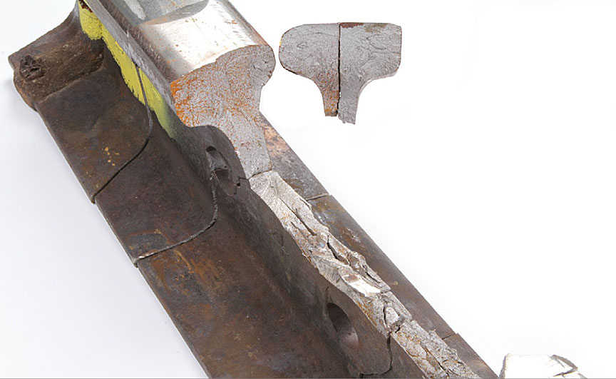

Deterioration of the running surface in the proximity of the thermite weld may have increased dynamic stresses in the area. This increase in stress combined with low ambient temperature and repeated wheel impacts due to the LSC also likely contributed to the rail failure.
Appendix B – National Transportation Safety Board reports involving crude oil trains
National Transportation Safety Board railroad accident brief relating to CSX Transportation petroleum crude oil train derailment and hazardous materials release at Lynchburg, VirginiaFootnote 91
On 30 April 2014, eastbound CSX Transportation (CSXT) petroleum crude oil unit train K08227 derailed 17 Class 111 tank cars at Mile 146.45 on main track 2 of the CSXT James River Subdivision in Lynchburg, Virginia, as a result of a defective rail. The train consisted of 2 locomotives, 1 buffer car, and 104 tank cars loaded with petroleum crude oil. It was 6426 feet long and weighed 14 107 tons. Due to track curvature in the area, a permanent maximum authorized speed limit of 25 mph was in place. The train was traveling at 24 mph at the time of the accident.
Three of the derailed cars were partially submerged in the James River. One was breached and released about 29 868 gallons of crude oil into the river, some of which caught fire. No injuries to the public or crew were reported. At the time of the accident, it was cloudy and raining lightly. The temperature was 53 °F.
National Transportation Safety Board factual report relating to CSX Transportation derailment at Mount Carbon, West VirginiaFootnote 92
On 16 February 2015, eastbound CSXT petroleum crude oil unit train K08014 derailed 27 loaded tank cars in Mount Carbon, West Virginia, as a result of a broken rail. The train consisted of 2 locomotives followed by a buffer car, 107 tank cars, and a tail end buffer car. The train was 6721 feet long and weighed 15 261 tons. The train was transporting about 3.1 million gallons of Bakken petroleum crude oil (UN1267, Class 3, packing group I) from Manitou, North Dakota, and was destined for Yorktown, Virginia. At the time of the accident, CSXT had implemented a temporary 40 mph speed restriction on the territory due to cold weather. The train was proceeding at 33 mph at the time of the accident. The temperature was 15 °F, and there was 8 inches of recent snow.
Of the 27 tank cars that derailed, 19 cars were involved in a pileup and a post-derailment pool fire. Two tank cars were punctured during the derailment and released product, and 4 other cars released product from either top or bottom fittings. The pool fire caused thermal tank shell failures on 13 tank cars that had initially survived the accident. A total of approximately 378 000 U.S. gallons (1.43 million litres) of product was released.
All tank cars involved in this accident were specification DOT-111A100W1 built to the Association of American Railroads (AAR) CPC-1232 industry standard. At the time of this accident, neither the DOT-111 tank cars nor those manufactured to the AAR CPC-1232 standard were required to be equipped with thermal protection systems to protect the tank from exposure to pool or torch fire conditions that can occur in accidents.Footnote 93
None of the tank cars had thermal protection. During the derailment sequence, 2 tank cars were punctured, and released more than 50 000 gallons of crude oil. Of the 27 tank cars that derailed, 19 cars were involved in a pileup and the post-derailment pool fire. The pool fire caused thermal tank shell failures on 13 tank cars that had initially survived the accident. Only 1 tank car at the edge of the pool fire survived without release. The other 8 derailed tank cars, which were positioned on either side of the pool fire, were not significantly damaged and did not release product.
On 12 April 2015, the National Transportation Safety Board issued to the Pipeline and Hazardous Materials Safety Administration 4 urgent safety recommendations that addressed the retrofitting of thermal protection systems for DOT- 111 tank cars used to transport Class 3 flammable liquids. The recommendations included:
Require that all new and existing tank cars used to transport all Class 3 flammable liquids be equipped with thermal protection systems that meet or exceed the thermal performance standards outlined in Title 49 Code of Federal Regulations 179.18(a) and are appropriately qualified for the tank car configuration and the commodity transported.Footnote 94
In conjunction with thermal protection systems called for in safety recommendation R-15-14, require that all new and existing tank cars used to transport all Class 3 flammable liquids be equipped with appropriately sized pressure relief devices that allow the release of pressure under fire conditions to ensure thermal performance that meets or exceeds the requirements of Title 49 Code of Federal Regulations 179.18(a), and that minimizes the likelihood of energetic thermal ruptures.Footnote 95
Require an aggressive, intermediate progress milestone schedule, such as a 20 percent yearly completion metric over a 5-year implementation period, for the replacement or retrofitting of legacy DOT-111 and CPC-1232 tank cars to appropriate tank car performance standards, that includes equipping these tank cars with jackets, thermal protection, and appropriately sized pressure relief devices.Footnote 96
Establish a publically available reporting mechanism that reports at least annually, progress on retrofitting and replacing tank cars subject to thermal protection system performance standards as recommended in safety recommendation R-15-16.Footnote 97
Appendix C – Census metropolitan areas
| CMA | 2012 | 2013 | 2014 | 2015 | |
|---|---|---|---|---|---|
| 1 | St. John's (NL) | 205.9 | 209.1 | 212.3 | 214.3 |
| 2 | Halifax (NS) | 406.7 | 410 | 413.6 | 417.8 |
| 3 | Moncton (NB) | 142.8 | 144.4 | 146.1 | 148 |
| 4 | Saint John (NB) | 128.5 | 128 | 127.5 | 126.9 |
| 5 | Saguenay (QC) | 160 | 160.3 | 160.4 | 160 |
| 6 | Québec (QC) | 785.2 | 793.6 | 800.9 | 806.4 |
| 7 | Sherbrooke (QC) | 207.5 | 210.1 | 212.6 | 214.5 |
| 8 | Trois-Rivières (QC) | 154.4 | 155.1 | 156 | 156.4 |
| 9 | Montréal (QC) | 3,937.40 | 3,985.10 | 4,028.00 | 4,060.70 |
| 10 | Ottawa-Gatineau (ON/QC) | 1,288.50 | 1,302.90 | 1,316.50 | 1,332.00 |
| 11 | Kingston (ON) | 165.9 | 167.1 | 168.5 | 169.9 |
| 12 | Peterborough (ON) | 122.7 | 123.1 | 122.8 | 122.6 |
| 13 | Oshawa (ON) | 373.8 | 379.1 | 384 | 389 |
| 14 | Toronto (ON) | 5,868.70 | 5,966.40 | 6,053.40 | 6,129.90 |
| 15 | Hamilton (ON) | 750.7 | 758.3 | 765.2 | 771.7 |
| 16 | St. Catharines-Niagara (ON) | 404 | 405.2 | 406.8 | 408.2 |
| 17 | Kitchener-Cambridge-Waterloo (ON) | 498.8 | 503.1 | 507.3 | 511.3 |
| 18 | Brantford (ON) | 140.4 | 141.8 | 142.8 | 143.9 |
| 19 | Guelph (ON) | 148 | 149.5 | 151.3 | 153 |
| 20 | London (ON) | 494.4 | 498.7 | 502.7 | 506.4 |
| 21 | Windsor (ON) | 330.8 | 332.5 | 334.3 | 335.8 |
| 22 | Barrie (ON) | 195.4 | 198 | 200.3 | 202.7 |
| 23 | Greater Sudbury (ON) | 165.5 | 165.7 | 165.3 | 164.8 |
| 24 | Thunder Bay (ON) | 125.1 | 125.2 | 124.9 | 124.7 |
| 25 | Winnipeg (MB) | 759.6 | 770.3 | 782.6 | 793.4 |
| 26 | Regina (SK) | 225 | 231.3 | 237 | 241.4 |
| 27 | Saskatoon (SK) | 281.4 | 291 | 298.9 | 305 |
| 28 | Calgary (AB) | 1,307.50 | 1,357.80 | 1,406.00 | 1,439.80 |
| 29 | Edmonton (AB) | 1,241.80 | 1,286.00 | 1,331.60 | 1,363.30 |
| 30 | Kelowna (BC) | 185.6 | 187.8 | 191.2 | 197.3 |
| 31 | Abbotsford-Mission (BC) | 176.7 | 178.5 | 181 | 183.5 |
| 32 | Vancouver (BC) | 2,408.10 | 2,438.70 | 2,475.70 | 2,504.30 |
| 33 | Victoria (BC) | 355.2 | 357.6 | 361.4 | 365.3 |
Source: Statistics Canada, CANSIM, table 051-0056 (10 February 2016)
Last modified: 2016-02-10.