Main-track derailment
Canadian National Railway Company
Freight train M39731-18
Mile 18.70, Strathroy Subdivision
Strathroy, Ontario
The Transportation Safety Board of Canada (TSB) investigated this occurrence for the purpose of advancing transportation safety. It is not the function of the Board to assign fault or determine civil or criminal liability. This report is not created for use in the context of legal, disciplinary or other proceedings. See Ownership and use of content. Masculine pronouns and position titles may be used to signify all genders to comply with the Canadian Transportation Accident Investigation and Safety Board Act (S.C. 1989, c. 3).
Summary
On 19 July 2017, at about 0415 Eastern Daylight Time, Canadian National Railway Company freight train M39731-18, proceeding westward on the Strathroy Subdivision, derailed 14 cars in the town of Strathroy, Ontario. The cars that derailed, including 1 dangerous goods residue tank car that last contained liquefied petroleum gas (UN1075), came to rest in the vicinity of the Metcalfe Street West crossing. There were no injuries, and there was no release of dangerous goods.
Le présent rapport est également disponible en français.
1.0 Factual information
On 18 July 2017, at approximately 2200,Footnote 1 westbound Canadian National Railway Company (CN) freight train M39731-18 departed MacMillan Yard, located in Vaughan, Ontario (Mile 0.0 of the Halton Subdivision), en route to Sarnia, Ontario (Figure 1). The train consisted of 2 head-end locomotives and 115 cars (23 loaded cars, 86 empty cars, and 6 residue cars). En route, the train crew stopped at Beachville, Ontario (Mile 57.94 of the Dundas Subdivision), picked up 11 additional loaded cars, and placed them in the train, behind the locomotives. After the train crew picked up the additional cars, the train consisted of 126 cars (34 loaded cars, 86 empty cars, and 6 residue cars). The train weighed a total of approximately 8215 tons and was about 9700 feet long. The train crew consisted of a locomotive engineer (LE) and a conductor. The crew members were familiar with the territory and were qualified for their positions.
1.1 The accident
On 19 July 2017, at about 0400, the train approached Strathroy, Ontario. After the locomotives passed through Strathroy, the LE heard the instrument display unit (IDU), located in the locomotive cab, sound an alarm. The alarm sounds when there is either a loss of brake pipe pressure at the tail end of the train or a communication loss between the IDU and the sense and braking unit (SBU) located on the tail-end car of the train. Believing that the IDU had lost communication with the SBU, the LE attempted to re-establish communication and noticed that the tail-end air brake pipe pressure was 0 psi.
Seconds later, a dragging equipment detector (DED), located at Mile 19.51, broadcast a warning to the crew over the radio indicating that dragging equipment had been detected from the 445th to 450th axles of the train. This equated to all 4 axles on the 109th car and the first 2 (leading) axles on the 110th car.
The LE brought the train to a controlled stop at Mile 22.34 with a split-service application of the train air brake.Footnote 2
1.2 Site examination
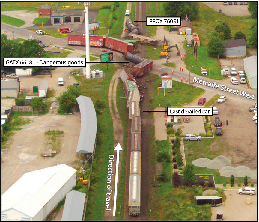
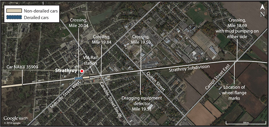
The site examination revealed that 14 cars had derailed (Figure 2). The 109th car from the head end, covered hopper car NAHX 35909 (load of cement) was oriented with the A-endFootnote 3 leading. It remained coupled to the head end of the train with all wheels on the rail. It came to rest about 2000 feet west of the derailment site. Although car NAHX 35909 was not derailed at the time of the examination, all 8 wheel treads were extensively scraped and gouged, consistent with being recently derailed. The wheel treads on car NAHX 35909 had the most tread damage of any of the derailed cars.
The 13 cars that followed car NAHX 35909 (the 110th to the 122nd cars) came to rest between the VIA Rail Canada Inc. (VIA Rail) platform (Mile 19.98) and approximately 350 feet west of the Metcalfe Street West crossing (Mile 20.04), in the downtown section of Strathroy. While the 109th and the 112th cars were loaded, all the other derailed cars were essentially empty.
The 110th car (PROX 76051) to the 112th car came to rest south of the main track, 200 to 350 feet west of the Metcalfe Street West crossing. All 3 cars were tank cars that came to rest coupled together, overturned on their sides and parallel to the track. The 113th car came to rest on its side across the track. The 114th car to the 118th car came to rest in various positions, on or adjacent to the crossing, diagonal to the track structure. The 117th car was residue dangerous goods tank car GATX 66181 that had last contained liquefied petroleum gas (UN1075). It came to rest on its side on the Metcalfe Street West crossing. The 119th car to the 121st car were derailed, parallel to the track structure and leaning at an angle of up to 40°. The 122nd car was the last to derail. It remained upright with the A-end truck derailed. There were no injuries, and there was no release of dangerous goods.
1.2.1 Examination of 109th car, NAHX 35909
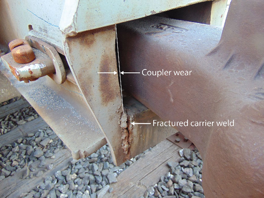
In addition to the damage to the wheels, a site examination of NAHX 35909 showed that both A‑end carrier welds were fractured. The right-sideFootnote 4 (R-side) coupler striker plate displayed wear that corresponded to the profile of a coupler shank (Figure 3).
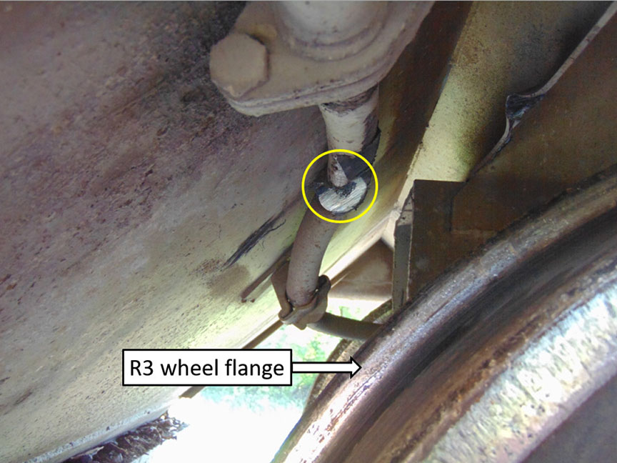
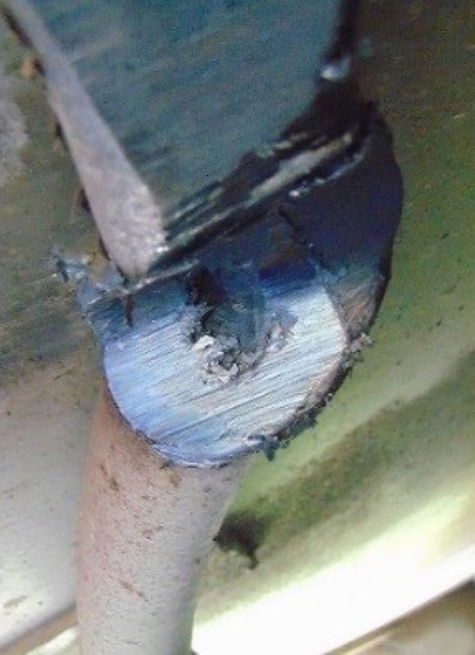
In addition, wheel flange friction burn/grind marks were observed on the air brake pipe near the R3Footnote 5 wheel. The air brake pipe was partially severed, allowing air to escape. The cut ends displayed signs of heat damage, and the melted metal reduced the diameter of the air brake pipe (Figure 4 and Figure 5).
Car NAHX 35909, including both trucks, was forwarded to CN's MacMillan Yard for detailed examination.
1.2.2 Examination of track infrastructure
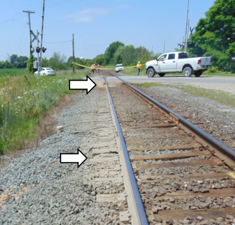
A wheel flange mark was observed on the running surface of the north rail head, 75 feet west of the Carroll Street East crossing at Mile 18.69.
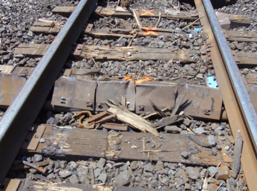
The wheel flange mark initiated on the gauge side of the rail and continued across the rail head diagonally westward for about 25 feet, then dropped off to the field side. From this location, wheel impact marks were observed on the rail base, tie plates, ties, spikes, and rail anchors, between the ties and on the field side of the north rail, extending westward to where the derailed cars came to rest in the vicinity of the Metcalfe Street West crossing at Mile 20.04 (Figure 6).
At the Carroll Street East crossing, ballast on both sides of the crossing was contaminated with mud. On the west side, the ballast between the rails and south of the south rail exhibited mud contamination along the first 30 feet west of the crossing (Figure 7). On the east side of the crossing, ballast between the rails and south of the south rail adjacent to the crossing was also contaminated with mud (Figure 8).
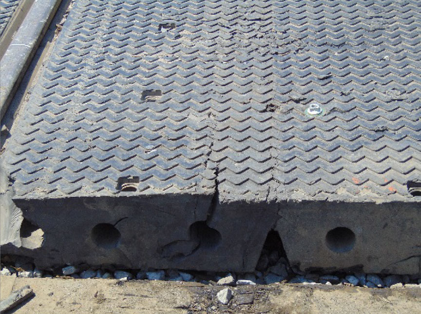
Slightly further west, the Queen Street crossing (Mile 19.50) displayed wheel impact marks on its rubber surface (Figure 9). A DED, located immediately west of the crossing (Mile 19.51), showed 3 sets of wheel impact marks on its deflection paddles (Figure 10). These marks continued on the ballast and track structure between the rails for about one third of a mile further westward to the Caradoc Street South crossing (Mile 19.84). At the Caradoc Street South crossing, the east end of the concrete surface displayed wheel flange marks about 6 inches north of the north rail that continued through to the west end of the crossing surface where they re-aligned back onto the rail.
Immediately west of the Caradoc Street South crossing, additional wheel marks were found on the field side of the north rail. These marks extended westward to Mile 19.98 where they intersected an asphalt platform adjacent to the track at the VIA Rail station. The platform was heavily damaged, and the track structure immediately west of the VIA Rail station platform and up to the Metcalfe Street West crossing was destroyed. Track damage was extensive west of Metcalfe Street West for about 350 feet, where the first derailed car came to rest.
1.3 Weather
Environment and Climate Change Canada records from a local weather station indicate that, at the time of the occurrence, the winds were calm and the temperature was 17 °C.
The average monthly precipitation amounts for April, May, and June are 85.7 mm, 77.2 mm, and 71.3 mm, for a 3-month total average of 234.2 mm. In 2017, the total precipitation for April, May, and June was 340.6 mm, an increase of 45% more than the average. While the amount of precipitation that the area had received was above average, the weather station had not recorded any precipitation in the 5 days preceding the occurrence.
1.4 Locomotive event recorders
The lead locomotive on the train, CN 5793, was built by General Motors Electro-Motive Division (EMD) in 1999. It is a 4300-horsepower model EMD SD-75I locomotive that is 73 feet long and weighs about 200 tons. The locomotive original equipment included a Q-Tron Model Data-cord 5100 locomotive event recorder (LER). The LER monitored and recorded 27 data channels, including time, distance, speed, brake pipe pressure, operator-initiated emergency brake application, and throttle position. However, this LER does not record end-of-train (EOT) air brake pipe pressure, nor is it required to do so. Locomotives of this vintage, equipped with similar LERs, are prominent throughout CN's fleet and the railway industry in general.
Of CN's fleet of 1448 high-horsepower main line locomotives, about 58% (835) do not record EOT air brake pipe pressure. In contrast, all main line locomotives built after 01 January 2007 and delivered after 01 January 2008 must be equipped with an LER that monitors and records EOT air brake pipe pressure.
1.4.1 Regulatory requirements for locomotive event recorders
The Transport Canada (TC) Railway Locomotive Inspection and Safety Rules prescribe the minimum safety standards for locomotives. Part II, Section 12, deals with the design requirements for event recorders and states the following:
Footnote 6Item 12(e) lists 26 data elements LERs are required to retain. Among them are the following:
- end-of-train device (EOT) device [sic] lost [sic] of communication front to rear and rear to front,
[…]
- EOT armed emergency brake command, emergency brake application,
- Indication of EOT valve failure,
- EOT brake pipe pressure (EOT and ECP [electronically controlled pneumatic] devices)Footnote 7
Section 12.1 addresses the implementation period and states the following:
- all locomotives, built prior to January 1, 2007 shall be equipped with an event recorder designed with a solid state memory module and shall record as a minimum the following data elements:
- time,
- distance,
- speed,
- brake pipe pressure,
- throttle position,
- emergency brake application,
- independent brake cylinder pressure,
- horn signal and where applicable the reset safety control function;
- all new locomotives built after Jan. 1, 2007 and delivered after January 1, 2008 shall be equipped with an event recorder designed with a "Certified Crashworthy" ERMM [event recorder memory module] that records all data elements contained in 12(e) [...].Footnote 8
When ordering new locomotives, each railway specifies the type of LER and the data elements to be recorded. While railways are required to record the minimum data elements outlined in the Railway Locomotive Inspection and Safety Rules, they are not limited by the rules and can specify that more elements be recorded. For example, Canadian Pacific Railway has required that EOT air brake pipe pressure be recorded on most of its main line locomotives, whereas, prior to 2007, CN required that its LERs record only the 8 data elements stipulated by the Railway Locomotive Inspection and Safety Rules that were in place at the time.
1.4.2 Recorded information
A review of the data from CN 5793's LER showed that, as the head end of the train was passing through Strathroy (Mile 18.69 to Mile 20.39), the train was increasing in speed from about 51 mph to 57 mph over almost the entire distance. From Mile 20.10 to Mile 21.06, train speed was held at a constant 57 mph. After Mile 21.06, train speed began to slow. Along this section of the track, the train was being handled with throttle manipulation, with the throttle handle being manoeuvred between position 3 and position 8. The air brake pipe pressure was holding at 88 psi on the lead locomotive. When the lead locomotive was at Mile 20.10, the 109th car was at about Mile 18.48.
Information recorded by the LER is shown in Table 1 below.
| Mileage | Time | Speed | Comment |
|---|---|---|---|
| Mile 21.05 to Mile 21.06 | 0412:51 to 0412:52 | 57 mph to 54 mph to 57 mph | A speed reduction of 3 mph followed by a speed increase of 3 mph. Air brake pipe pressure at 88 psi. |
| Mile 21.41 | 0413:14 | 56 mph | Start of initial split-service air brake application with reduction of air brake pipe pressure from 88 psi to 86 psi. |
| Mile 21.55 | 0413:23 | 54 mph | End of initial split-service air brake application with air brake pipe pressure at 82 psi. |
| Mile 21.72 | 0413:35 | 50 mph | Start of remaining service air brake application with air brake pipe pressure at 80 psi. |
| Mile 22.30 | 0414:34 | 17 mph | End of service air brake application with air brake pipe pressure at 71 psi. |
| Mile 22.34 | 0414:52 | 0 mph | The train came to rest with the air brake pipe pressure at 71 psi. |
| Mile 22.34 | 0416:39 | 0 mph | Air brake pipe pressure at 87 psi. |
| Mile 22.34 | 0420:01 | 0 mph | Air brake pipe pressure at 56 psi. |
No emergency brake application occurred during this sequence. The train was handled in accordance with company and regulatory requirements.
1.5 Subdivision information
The Strathroy Subdivision consists of a single main track that extends from Mile 0.0 (London, Ontario) to Mile 61.7 (Port Huron, Michigan, United States). Train movements are governed by the centralized traffic control system method of train control, as authorized by the Canadian Rail Operating Rules, and are supervised by a rail traffic controller located in Toronto, Ontario. There are about 14 freight trains and 10 passenger trains daily. Annual tonnage over the subdivision is about 49 million gross tons.
In the vicinity of the occurrence, the Strathroy Subdivision is classified as Class 4 track according to the TC-approved Rules Respecting Track Safety, also known as the Track Safety Rules(TSR). Authorized speed is 60 mph for freight trains and 80 mph for passenger trains. The track is generally oriented east to west and descends toward the west from Mile 16.0 to Mile 20.48 at a grade of up to 0.41%. From Mile 20.48 to Mile 22.70, the track ascends at a grade of up to 0.31%.
Track infrastructure consists of 132-pound and 136-pound RE continuous welded rail, laid on double-shouldered tie plates. Each tie plate is secured to the tie with 3 spikes. The ties are box-anchored every other tie. The ballast consists of crushed rock. The cribs were full, and the shoulders extended at least 12 inches beyond the end of the ties.
The Carroll Street East crossing is located in the body of a 3145-foot, 0.51° left-hand curveFootnote 9 that extends from Mile 18.43 to Mile 18.98. This portion of the curve has a constant 3.23‑inch superelevation.
1.6 Track inspection
The TSR prescribe the minimum requirements for the frequency and manner of inspecting track to detect deviations from the TSR. When a deviation from the TSR occurs, remedial action must be initiated immediately.
1.6.1 Visual track inspections
According to the TSR, Class 4 track with more than 15 million gross tons of traffic annually must be inspected at least twice weekly, which CN did for the Strathroy Subdivision. The last inspection occurred on 16 July 2017 with no defects noted in the vicinity of Mile 18.70.
1.6.2 Rail flaw detection testing
According to the TSR, continuous welded rail in Class 4 track with at least 35 million gross tons of traffic annually must be inspected for internal defects no less than 4 times per year. CN inspected the Strathroy Subdivision ultrasonically approximately 12 times per year. The subdivision was last tested on 13 June 2017. No defects were noted in the vicinity of Mile 18.70.
1.6.3 Geometry car testing
According to the TSR, Class 4 track with at least 35 million gross tons of traffic annually must receive an electronic geometry inspection at a minimum frequency of twice annually with a heavy geometry inspection vehicle.Footnote 10 CN exceeded these requirements and conducted 5 heavy geometry car inspections in 2016 and 4 in 2017 (including after the occurrence). The last track geometry test prior to the occurrence (19 July 2017) was conducted on 12 April 2017. No priority or urgent geometry defects were detected in the vicinity of Mile 18.70.
However, a review of the 12 April 2017 test graph showed that a Surface 62Footnote 11 measurement of the south rail of −0.79 inches was recorded just east of the Carroll Street East crossing, while just west of the Carroll Street East crossing, a measurement of −0.47 inches was recorded. Neither of these conditions was considered a defect requiring remedial action or monitoring according to the TSRFootnote 12 or the CN Engineering Track StandardsFootnote 13 (ETS).
A Warp 62Footnote 14 measurement of 0.984 inches was recorded at Mile 18.69, below the threshold requiring remedial action or monitoring according to the TSRFootnote 15 and the ETS.Footnote 16 Track warp can be caused by mud pumping. If the warp is severe enough, the risk of some car wheels climbing or lifting increases.
1.6.4 Rail head wear
The TSR require that each railway company have written requirements establishing maximum rail wear limits. Section 1.0, item 23 of the CN ETS states the following:
- The maximum allowable vertical wear for 132‑pound rail is 16 mm; for 136‑pound rail, it is 20 mm.
- The maximum allowable gauge face wear for both 132‑pound rail and 136‑pound rail is 16 mm.
The heavy geometry inspection vehicle recorded the rail designation and wear at Mile 18.616 and Mile 18.70. At Mile 18.616, the north rail was 132-pound RE rail with 11.89 mm of vertical wear and 7.28 mm of gauge face wear. The south rail was 136-pound RE rail with 4.22 mm of vertical wear and 0.06 mm of gauge face wear.
At Mile 18.70, both rails were 132-pound RE rail. The north rail had 2.67 mm of vertical wear and 0.24 mm of gauge face wear. The south rail had 4.35 mm of vertical wear and 0.25 mm of gauge face wear.
The rail head wear was within CN ETS requirements.
1.7 Freight car regulatory and industry standards
The Association of American Railroads (AAR) publishes the Field Manual of the AAR Interchange Rules (AAR Interchange Rules) to provide an equitable basis for charging car owners for repairs and damages to rail cars. The manual details the applicable condemning limits for all car parts and conditions, including wedge rise, side bearing clearance and coupler height. Once these limits are either reached or exceeded, repairs are warranted.
Rule 16 of the 2017 version of the manual states the following:
12. Required Coupler Heights
a. Empty cars – Minimum 32 ½ inches, Maximum 35 inchesFootnote 17
Rule 46 states the following:
2. Condemnable When Car Is on Shop or Repair Track for Any Reason
a. Friction casting (wedge) rise height measured by an approved method exceeding the limits indicated in Figures A-1, A-2, A-3, B-1, C-1, D-1 or manufacturer's recommendations.Footnote 18
Rule 46, Figure A-1, indicates that, for 70- and 100-ton ride control trucks, the limit for wedge rise height is 113/16 inches. Wedge rise exceeding 113/16 inches is condemnable.
Rule 62 states the following:
1. Condemnable at Any Time
h. Roller or solid block type side bearings with clearance less than 3/16 inch or greater than 5/16 inch.Footnote 19
The TC-approved Railway Freight Car Inspection and Safety Rules prescribe the minimum safety standards for freight cars. Part II contains those safety defects that, when present, prohibit a railway company from placing or continuing a freight car in service. Part II, Item 13, addresses trucks and states the following:
13.1 A railway company shall not place or continue a car in service if:
[…]
- a truck is equipped with an ineffective damping mechanism as indicated by:
- a side frame column wear plate missing (except by design), or broken to the extent that it no longer performs it[s] design function;
- a broken or missing activating side spring;
- truck springs that show evidence of not maintaining travel or load;
- hydraulic snubbers with an accumulation of wet fluid and fluid is not visible in the sight glass if so equipped;
- truck springs compressed solid;
- truck springs on which more than one of the outer springs in any spring cluster are broken, out of place or missing; or
- a friction wedge is missing, broken to the extent that it becomes non functional or worn beyond the wear indicator.
- the truck side bearings:
[…]
- at one end of the car have a total clearance from the body side bearing of more than ¾ inches (19.05 mm); or
- at diagonally opposite sides of the car, have a total clearance from the body side bearing of more than ¾ inches (19.05 mm).Footnote 20
Part II, Item 15, addresses couplers and states the following:
15.1 A railway company shall not place or continue a car in service if:
[…]
(i) the coupler heights between two adjacent freight cars vary in excess of 4 inches (101.6 mm);Footnote 21
The Railway Freight Car Inspection and Safety Rules do not prescribe measured limits for friction wedge rise. The rules also do not prescribe side bearing clearance limits for individual positions of the side bearings, but instead focus on the sum of one car end and the sum of diagonally opposite sides of the car.
1.8 Covered hopper car NAHX 35909
Car NAHX 35909 was built in August 1978. The trucks, original to the car, were 100-ton ASF ride control trucks consisting of 6½ × 12 roller bearings, 36-inch wheels, gapped steel block side bearings, D5 main springs, and friction wedges with corresponding 3091 and 3092 outer and inner control springs, respectively. The car was 41 feet 11 inches in length, had a truck centre distance of 26 feet 3 inches, and a distance between the lead and trailing wheels of about 32 feet.
Both ends of the car were equipped with E60-type couplers and E50-type knuckles. By design, the nominal coupler swing angle limit for an E60-type coupler is about 7°.Footnote 22
On 15 August 2017, a detailed inspection of car NAHX 35909 was performed. The A-end and B-end brake pipe fittings were attached to an air supply. In each case, air flowed through the partially severed air brake pipe and out of the cut in the pipe at the A-end truck. Both trucks from NAHX 35909 were removed from the car, disassembled and examined. Some critical measurements recorded during the teardown are in Table 2 below. Measurements that are at or exceed the specified limits are marked with an asterisk.
| Condition | Measurements | AAR maintenance criteria | Railway Freight Car Inspection and Safety Rules criteria |
|---|---|---|---|
| Friction wedge rise | A-end truck:
|
Wedge rise exceeding 113/16 inches is condemnable. | A railway company shall not place or continue a car in service if a truck is equipped with an ineffective damping mechanism as indicated by a friction wedge that is missing, broken to the extent that it becomes non-functional, or worn beyond the wear indicator (subsection 13.1(b)vii). |
| Side bearing clearance | A-end truck:
|
|
A railway company shall not place or continue a car in service if the truck side bearings at 1 end of the car have a total clearance from the body side bearing of more than ¾ inches (19.05 mm) (subsection 13.1(c)iv). A railway company shall not place or continue a car in service if the truck side bearings at diagonally opposite sides of the car have a total clearance from the body side bearing of more than ¾ inches (19.05 mm) (subsection 13.1(c)v). |
| Coupler height (empty car)** | A-end truck:
B-end truck:
|
Empty cars:
|
A railway shall not place or continue a car in service if the coupler heights between 2 adjacent freight cars vary in excess of 4 inches (101.6 mm) (subsection 15.1(i)). |
* This measurement is at or exceeds the specified limit.
** Coupler carriers at both ends of the car were missing coupler carrier plates/shims when inspected.
1.8.1 Freight car maintenance
The AAR Interchange Rules contain numerous rules regarding the maintenance and upkeep of cars intended for interchange between railway companies. CN repairs cars according to the AAR Interchange Rules. To aid mechanical inspectors when inspecting to these rules, CN has developed a checklist entitled "DYC (Did You Check) Requirements" that lists the key car components and structures to be inspected. No measurements are recorded, but mechanical inspectors are required to initial each item on the checklist to show that the item was checked.
The DYC Requirements checklist separates the items into those that must be inspected when the car is on shop and repair tracks, wheel change tracks, speedy/expedite and line or road tracks, and the intermodal pad and yard tracks. Side bearing clearances must be inspected when cars are on shop and repair tracks. Friction wedge rise is not listed on the checklist.
On 06 April 2017, car NAHX 35909 was sent to the repair track in CN's MacMillan Yard for repairs to the A end of the car. The draft key retainer and lock were replaced; the yoke was cracking, the draft gear and follower plate were broken, and all 3 components were replaced. The work also included removing and replacing the draft gear carrier plate. There was no record of low coupler height at either end of the car. A DYC Requirements checklist was completed for this car and indicated that the side bearings had been checked.
1.8.2 Certified car inspections
CN inspects rail cars according to the Railway Freight Car Inspection and Safety Rules standards. In CN's "Car Inspection Train Yard" course, mechanical inspectors are instructed on the proper procedures when inspecting rail cars. When instructed on inspecting trucks, they are taught to inspect the friction wedges and wear plates. Friction wedges must not be broken, missing, or worn beyond the wear indicator. Truck side column wear plates, against which friction castings (wedges) ride, must not be missing or broken.
From 10 April 2017 and 18 July 2017, car NAHX 35909 received a total of 12 certified car inspections, 6 of which occurred in MacMillan Yard. No deficiencies were noted.
1.9 Friction wedge rise
The friction wedge vertical face, the side frame column vertical face, and the bolster pocket slope face act together to provide stability to the freight car truck. When the contact surfaces in any of these components wear to the condemning limits, a loss in truck squaring/damping occurs. A loss in squaring/damping can reduce the truck's ability to absorb or damp track profile conditions encountered and can result in wheel climb or wheel lift under certain conditions.
When new, the ASF ride control truck has a friction wedge rise of 15/16 inch. According to Rule 46 of the AAR Interchange Rules, when wedge rise on ride control trucks exceeds 113/16 inches, it is condemnable when the car is on a repair track. Theoretically, wear on an individual friction wedge, side frame column, or bolster pocket may not be condemnable, but the combined wear of the 3 components in 1 location could result in wedge rise that is condemnable. Friction wedge rise is considered to be indicative of a truck that is losing stability and may become problematic (Figure 11).
1.10 In-train forces
Longitudinal train forces are transmitted through the train between the coupler pivot points. When a train is pulled on tangent track, the train is typically experiencing draft forces (that is, tensile forces acting along the centreline of the track). When a train is operating on curved track, the longitudinal forces, whether buff (compressive) or draft (tensile), and related coupler angles result in lateral forces at the vehicle centre plates and at the car wheel flanges. Typically, the industry considers 100 000 pounds to be the safe upper limit for instantaneous in-train buff or draft force.
The magnitude of the lateral forces at the rail vary based on the magnitude of the longitudinal force, the coupler angle, the track grade, and the degree of track curvature. When a train is in buff state (compression) in a curve, the coupler swing angle can reach its maximum, with the coupler shanks pushing against the side of the coupler striker plate, which is secured to the end of the car centre sill. Longitudinal forces resulting from the compressional force transform into lateral force at the vehicle centre plates, which in turn transmits to the wheel flanges on the high rail of a curve.
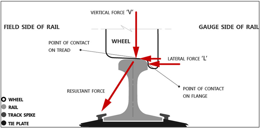
A combination of lateral (L) and vertical (V) forces exists where the wheel flange contacts the rail head (Figure 12). The ratio of lateral-to-vertical (L/V) forces indicates the probability of a derailment. The probability of a derailment increases as the L/V ratio increases. The highest L/V ratios typically occur when there is a sudden reduction in vertical load or a sudden increase in lateral load. A high lateral force combined with a low vertical force tends to push a wheel flange up and over the gauge face of the rail onto the rail head (wheel climb). A wheel L/V ratio of between 0.80 and 0.90 of sufficient durationFootnote 23 is known to cause wheel climb.Footnote 24Footnote 25
1.11 Track/train dynamics analysis
The TSB laboratory completed a train dynamics simulation using the Train Energy and Dynamics Simulator (TEDS) software program in conjunction with a 3-dimensional vehicle/track dynamics simulation using the Vehicle Analysis Modeling Package in the Railway Environment (VAMPIRE) software program.
The TEDS examined longitudinal speed, acceleration, in-train force, stop distance, etc. The simulation showed that, although not of a large magnitude, the A end of the 109th car would have experienced a buff (compression) force of 40 kipsFootnote 26 just west of the Carroll Street East crossing. Although this calculated force is well within normal in-train buff forces, it can still be problematic under a given combination of multiple conditions.
VAMPIRE analyzes the behaviour of single rail vehicles and the vehicle/track interaction. The simulation used
- the measured profile of the rail at Mile 18.699;
- the measured profile of the wheels from the 4th axle (leading axle) of car NAHX 35909;
- an estimated maximum coupler swing angle of 9°, taking into consideration the wear on draft components and the worn striker plate from the A end of car NAHX 35909;
- track stiffness parameters that were estimated to account for the asphalt crossing and the mud-pumping sections;
- track geometry conditions that were assumed to have deteriorated due to the unusually heavy rainfall during the 3 months that followed the most recent track geometry inspection. The conditions were assumed to be no more than priority level, which is still within the TSR limits;
- measured truck friction wedge wear and the resulting wedge rise;
- block side bearing clearance measurements; and
- the TEDS-calculated in-train compressional force.
The VAMPIRE simulation identified that a combination of factors present in this occurrence would have generated a high wheel L/V ratio of 0.82 and high lateral forces that acted on the R4 wheel of car NAHX 35909 while it was at Mile 18.70, just west of the Carroll Street East crossing located at Mile 18.69. The track/train dynamics analysis concluded that the initial wheel climb of car NAHX 35909 over the curve was most likely caused by a combination of the following 6 conditions:
- Friction wedge rise. The L3 wedge rise on car NAHX 35909 had reached the AAR Rule 46 limit of 113/16 inches. This reduced the truck squaring and damping forces, and contributed to the elevated L/V ratio. When compared with the calculated L/V ratio of 0.82 in the occurrence case, with no wedge rise, the maximum L/V ratio at the initial derailment location was calculated to be 0.25. The wedge rise was the most influential of the 6 conditions that contributed to this occurrence.
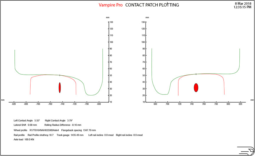
- Wheel/rail contact. When compared with the calculated L/V ratio of 0.82 in the occurrence case, with optimal wheel rail contact, the maximum L/V ratio at the initial derailment location was calculated to be 0.33. The effect of wheel/rail contact was another influential contributing factor in this occurrence (Figure 13 and Figure 14).
- Elevated coupler swing angle, due to the worn R-side coupler striker and cracked carrier, under moderate in-train buff force. A coupler swing angle of 1° was simulated and compared with the occurrence case using an estimated coupler swing of 9°. When compared with the calculated L/V ratio of 0.82 in the occurrence case, with a coupler swing angle of 1°, the maximum L/V ratio at the initial derailment location was calculated to be 0.36. The effect of coupler angularity under buff force was another influential contributing factor in this occurrence. The position of the car and A-end coupler with a moderate train buff force produced a larger-than-usual coupler swing angle, which transformed to lateral force and increased the L/V ratio at the initial derailment location.
- Uneven track stiffness. The initial derailment location was located near an asphalt level crossing and soft spots of mud pumping on the low (south) rail side. To determine the effect of uneven track stiffness, an assumed case with uniform track stiffness was simulated and compared with the occurrence case with uneven track stiffness. When compared with the calculated L/V ratio of 0.82 in the occurrence case, with uniform track stiffness, the maximum L/V ratio at the initial derailment location was calculated to be 0.43. The uneven track stiffness distribution contributed to the elevated L/V ratio calculated at the initial derailment location.
- Track geometry conditions. The mud pumping and contaminated ballast at the initial derailment location suggest that track geometry conditions in the vicinity were deteriorating.
An assumed case of the occurrence car over an ideal curve was simulated for comparison with the occurrence case. The simulated dynamic forces and L/V ratios on an ideal curve would be very small. Under these conditions, the curve entrance spiral and the uneven track stiffness at the crossing would generate some dynamic responses, but they would attenuate very quickly. This indicated that the car was not in hunting mode on the curve.
Using the track geometry test results from the 12 April 2017 test, another simulation was conducted. This simulation was based on the assumption that there was no further degradation of the track infrastructure in the 3 months following the test. With no further degradation of the track infrastructure, the maximum L/V ratio at the initial derailment location was calculated to be 0.53.
Due to an unusually high level of rainfall in the 3 months following the geometry test, track surface, and cross-level conditions at the initial derailment location likely further deteriorated and contributed to the calculated L/V ratio of 0.82 in the occurrence case. - Excessive side bearing clearances. The side bearing clearances on the R side of car NAHX 35909 exceeded the AAR Rule 62 condemning limit of 5/16 inch. This reduced the car's ability to restrain dynamic rock and roll movement, and increased the L/V ratio. When compared with the calculated L/V ratio of 0.82 in the occurrence case, with side bearing clearances at the AAR limit of 5/16 inch, the maximum L/V ratio at the initial derailment location was calculated to be 0.79. With multiple conditions present at the time of the derailment, marginal side bearing clearance would still generate a risk of an elevated L/V ratio.
The simulations showed that if any 1 of the 6 conditions analyzed was removed, the L/V ratio remained below the level at which such derailments typically occur.
1.12 TSB laboratory reports
The TSB completed the following laboratory report in support of this investigation:
- LP177/2017 – Track/Train Dynamics Analysis
2.0 Analysis
Train handling did not play a role in this occurrence. The analysis will focus on the condition of the track and rolling stock, the inspection of rolling stock, and the requirements to record locomotive event recorder (LER) channels.
2.1 The accident
A 25‑foot wheel flange mark observed on the running surface of the north rail head just west of the Carroll Street East crossing (Mile 18.69) identified the initial point of derailment POD). The wheel flange mark initiated on the gauge side of the rail and continued diagonally westward across the rail head, then dropped off to the field side, which was indicative of a derailment initiated by wheel climb.
When compared to the other derailed cars, the 109th car (NAHX 35909) exhibited the most damage to its wheel treads, indicating that it was the first car to derail. With its A end leading, the right-side (R-side) wheels of the car traversed the north rail with the R4 wheel in the lead position. Considering these factors, the derailment initially occurred when the R4 wheel of car NAHX 35909 climbed the high (north) rail of the curve just west of the Carroll Street East crossing, located at Mile 18.69 of the Strathroy Subdivision.
Car NAHX 35909 and the leading end of the 110th car (PROX 76051) continued westward in a derailed condition for 1.15 miles until they struck the Caradoc Street South concrete crossing surface at Mile 19.84, where car NAHX 35909 re-railed itself and car PROX 76051 remained derailed. Upon reaching the VIA Rail Canada Inc. platform, the trailing B end of car NAHX 35909 separated from car PROX 76051, and the 13 cars behind car NAHX 35909 derailed and then came to rest in the vicinity of the Metcalfe Street West crossing (Mile 20.04), in downtown Strathroy, Ontario.
2.2 Freight car and track infrastructure conditions
Freight car and track inputs were used to conduct a train dynamics analysis to calculate the ratio of lateral-to-vertical (L/V) forces and identify the potential for derailment. A wheel L/V ratio of between 0.80 and 0.90 of sufficient duration is known to cause wheel climb. For the initial wheel climb of the R4 wheel of car NAHX 35909 over the high rail of the curve, the calculated L/V ratio was 0.82, indicating a likely derailing condition. The following conditions played a role in the occurrence.
2.2.1 Covered hopper car NAHX 35909
Side bearing clearance on the R side of both trucks of car NAHX 35909 exceeded the Association of American Railroads (AAR) condemning limits requiring repairs, but met the Transport Canada–approved Railway Freight Car Inspection and Safety Rules requirements. The excessive side bearing clearances on the R side reduced the ability of car NAHX 35909 to restrain dynamic rock and roll movement, and contributed to the elevated L/V ratio.
Friction wedge rise in the A-end L3 position was at the limit of the AAR threshold and was not condemnable under the Railway Freight Car Inspection and Safety Rules, which are silent on wedge rise. The friction wedge rise in the A-end L3 position of car NAHX 35909 reduced the truck squaring and damping forces, and contributed to the elevated L/V ratio.
The R-side weld securing the A-end coupler carrier was cracked, which suggests that a higher-than-usual force was applied to the R-side coupler striker plate by the coupler shank. The A-end, R-side vertical coupler striker plate of car NAHX 35909 exhibited wear that permitted the coupler swing angle to increase beyond the established nominal limit of 7° for E60-type couplers.
2.2.2 Buff force
When a train is in buff state (compression) in a curve, the coupler swing angle can reach its maximum with the coupler shanks pushing against the side of the coupler striker plate, which is secured to the end of the car centre sill. Longitudinal forces resulting from the compressional force transform into lateral force at the vehicle centre plates, which in turn transmits to the wheel flanges on the high rail of a curve.
Train dynamics analysis identified that a compressional force of 40 kips from a run-in of trailing tonnage acted on car NAHX 35909 at the POD. Typically, the industry considers 100 000 pounds (100 kips) to be the safe upper limit for instantaneous in-train buff or draft force. The modelled buff force was well within industry operational practices. However, the run-in of trailing tonnage gave the car a small bump at the precise time at which the car was vulnerable.
As car NAHX 35909 traversed the curve with the A-end coupler at its maximum lateral swing angle, it was subjected to a moderate train buff force that transformed longitudinal force to lateral force and increased the L/V ratio at the initial POD.
2.2.3 Wheel/rail profiles
When compared with the calculated L/V ratio of 0.82 in the occurrence case, with optimal wheel rail contact, the maximum L/V ratio at the initial POD was 0.33. The effect of wheel/rail contact was another influential factor that contributed to the elevated L/V ratio and subsequent wheel climb. The wheel/rail profiles at the initial POD created contact conditions that also contributed to the wheel climb.
2.2.4 Track infrastructure
Just east of the POD, track stiffness had been diminished by the presence of areas of heavy mud pumping on the south rail, which could contribute to reduced vertical force for mate wheels traversing the north rail. The heavy mud pumping not only produced uneven track stiffness distribution between the crossing surface and the track section to the west, but also affected the track surface and cross-level. Emerging track surface and cross-level conditions approaching the POD were identified in the 12 April 2017 track geometry inspection, but were not severe enough to require any immediate remedial action because they were below the criteria outlined in the TC-approved Track Safety Rules (TSR). However, due to an unusually high level of rainfall in the 3 months preceding the accident, emerging track surface and cross-level conditions at the initial POD location likely further deteriorated and contributed to the elevated L/V and subsequent wheel climb associated with the R4 wheel of car NAHX 35909.
The initial wheel climb of car NAHX 35909 over the high rail of a curve was caused by 6 conditions that combined to contribute to a calculated L/V ratio of 0.82, which indicates a derailing condition. Train dynamics analysis concluded that the combination of excessive R-side freight car side bearing clearances, L3 friction wedge rise, elevated A-end coupler swing angle due to component wear and buff force, wheel/rail contact conditions, uneven track stiffness, and track geometry conditions created the conditions for a wheel climb derailment to occur, with a calculated high wheel L/V ratio of 0.82. Train dynamics analysis determined that if any 1 of the 6 conditions analyzed was removed, the L/V ratio remained below the level at which such derailments typically occur.
2.3 Train emergency air brake application
After the locomotives passed through Strathroy, the locomotive engineer (LE) heard the instrument display unit (IDU) alarm, which sounds when there is either a loss of brake pipe pressure at the tail end of the train or a loss of communication between the IDU and the tail-end sense and braking unit (SBU). Believing that it was a loss of communication, while attempting to re-establish communication with the SBU, the LE noted that the brake pipe pressure was at 0 psi. Seconds later, a dragging equipment detector (DED) located at Mile 19.51, just west of the Queen Street crossing (Mile 19.50), broadcasted a warning to the crew over the radio indicating that dragging equipment had been detected for all 4 axles on the 109th car (NAHX 35909) and the first 2 (leading) axles on the 110th car (PROX 76051).
Car NAHX 35909 travelled 1.15 miles between the Carroll Street East crossing, where it derailed, and the Caradoc Street South crossing, where it re-railed itself. As the car travelled westward in a derailed condition, the leading A-end truck was skewed such that the R3 wheel partially burnt/ground through the air brake pipe and released air pressure.
The train then separated between the 109th car (NAHX 35909) and the trailing 110th car (PROX 76051). The 109th car remained on the rails attached to the head end of the train while the 110th to the 122nd cars derailed behind. Despite a hole ground into the air brake pipe by the R3 wheel of car NAHX 35909 (109th car) and by the separation of the air brake line between the 109th and 110th cars, no train-initiated emergency air brake application occurred and the LE brought the train, with the remaining 109 cars, to a controlled stop.
Without any recorded end-of-train (EOT) air brake pipe pressure, it could not be accurately determined whether the emergency brakes at the tail end of the train activated or when the tail-end air brake pipe pressure started to drop. However, as the R3 wheel flange of car NAHX 35909 partially burnt/ground through the air brake pipe, the pipe diameter was reduced and contact with the wheel flange partially sealed the air brake pipe such that air was released at a rate that was insufficient to trigger a train-initiated emergency brake application. Because the train came apart behind the partially severed air brake pipe, any train-initiated emergency brake application that may have occurred on the tail-end cars could not have propagated to the head end of the train.
2.4 Data elements required for locomotive event recorders
To accurately reconstruct the manner in which a train air brake system was operated, it is crucial to have air brake pipe pressure readings from both the head end and tail end of the train. However, in this occurrence, Canadian National Railway Company (CN) locomotive CN 5793 (built in 1999) was not equipped with an LER that recorded EOT air brake pipe pressure, nor was it required to be.
TC recognized the value of recording this type of data and approved the revised Railway Locomotive Inspection and Safety Rules in 2007. The revised rules required all new locomotives built after 01 January 2007 and delivered after 01 January 2008 to be equipped with LERs that record the 26 specified data elements listed in Section 12(e) of the rules, which includes EOT air brake pipe pressure. However, the revised rules also included a grandfather clause that permitted locomotives built before 01 January 2007 to operate with LERs that only recorded the 8 data elements specified in Section 12.1 of the rules, which do not include EOT air brake pipe pressure. Therefore, many pre-2007 locomotives in Canada still do not record EOT air brake pipe pressure, nor are they required to do so.
When ordering new locomotives, each railway specifies the type of LER and the data elements to be recorded. While railways are required to record the minimum data elements outlined in the Railway Locomotive Inspection and Safety Rules, they are not limited by the rules and can specify that more elements be recorded. For example, Canadian Pacific Railway has required that EOT air brake pipe pressure be recorded on most of its main line locomotives. Prior to 2007, CN required that its LERs record only the 8 data elements required by the Railway Locomotive Inspection and Safety Rules that were in place at the time. Since most of CN's current high-horsepower main line locomotive fleet was built before 2007, about 58% of its LERs still do not record EOT air brake pipe pressure.
In this occurrence, because the LER did not record EOT air brake pipe pressure, it could not be determined precisely when the EOT air brake pipe pressure began to drop, nor at what rate. Consequently, a key piece of information was not available to assist in a more thorough understanding of all the derailment events. If main line head-end locomotives are not equipped with locomotive event recorders that record end-of-train air brake pipe pressure, crucial information about events leading up to the accident will not be recorded, increasing the risk that industry and accident investigators will be deprived of valuable information that could enhance safety.
2.5 Friction wedge rise
The friction wedge vertical face, the side frame column vertical face, and the bolster pocket slope face act together to provide stability to a freight car truck. When these contact surfaces wear to the condemning limits for repair, a loss in truck squaring/damping occurs. A loss in squaring/damping can reduce a truck's ability to absorb track profile conditions and can result in wheel climb or wheel lift under certain conditions.
When new, the ASF ride control truck has a friction wedge rise of 15/16 inch. According to Rule 46 of the Field Manual of the AAR Interchange Rules (AAR Interchange Rules), when average wedge rise on one side of a ride control truck exceeds 113/16 inches, it is condemnable when the car is on a repair track. Although wear on an individual friction wedge, side frame column or bolster pocket may not be condemnable, the combined wear of the friction wedge vertical face, the side frame column vertical face, and the bolster pocket slope face in 1 location could result in wedge rise that is condemnable under the AAR Interchange Rules. Friction wedge rise is considered to be indicative of a truck that is losing stability and may become problematic.
During the post-occurrence teardown of the A-end truck of car NAHX 35909, the recorded L3 friction wedge rise was 113/16 inches, which was the limit outlined in Rule 46 of the AAR Interchange Rules. Furthermore, track/train dynamics analysis concluded that the L3 friction wedge rise was the most influential condition in this occurrence because it reduced the truck squaring and damping forces, and contributed to the elevated L/V ratio.
CN inspects in-service cars according to the Railway Freight Car Inspection and Safety Rules. The rules do not refer to any measurable wear limits for wedge rise. The rules require only that friction wedges be replaced when they are worn beyond the vertical face wear indicator. The rules do not include safe measured limits for friction wedge rise resulting from the combined wear of the friction wedge vertical face, the side frame column vertical face and the bolster pocket slope face. If there are no specific measured inspection criteria for friction wedge rise to identify trucks with excessively worn damping mechanism components, potentially unstable trucks can remain in service, increasing the risk of derailment.
2.6 Side bearing clearance
Post-occurrence inspection of the trucks of car NAHX 35909 confirmed that the side bearings on the R side met the Railway Freight Car Inspection and Safety Rules requirements, which focus on the sum of one car end and the sum of diagonally opposite ends of the cars. However, they did not meet the requirements set out in Rule 62 of the AAR Interchange Rules for repairing side bearing clearance.
The TSB VAMPIRE simulation showed that, had the side bearing clearances on the R side been at the 5/16-inch limit permitted under the AAR Interchange Rules, the maximum wheel L/V ratio at the initial POD location would have been reduced to 0.79, which indicates a potential for derailment.
2.7 Canadian National Railway Company checklist
CN has developed a checklist entitled "DYC (Did You Check) Requirements" that lists the key car components and structures to be inspected when a car is on shop and repair tracks, wheel change tracks, the speedy/expedite and line or road tracks, and the intermodal pad and yard tracks. No measurements are recorded, but mechanical inspectors are required to initial each item on the checklist to show that the item was checked. Side bearing clearances must be inspected when cars are on shop and repair tracks. Friction wedge rise was not listed on any of the checklists.
On 06 April 2017, car NAHX 35909 was sent to the repair track in CN's MacMillan Yard located in Vaughan, Ontario, for repairs to the A end of the car. A CN DYC Requirements checklist was completed, and a mechanical inspector initialed to indicate that the side bearings had been checked, but no measurements were recorded.
On 15 August 2017, a detailed inspection of car NAHX 35909 was performed at CN's MacMillan Yard. During the inspection, the A-end truck recorded friction wedge rise at the L3 position that was at the limit of Rule 46 of the AAR Interchange Rules, and side bearing clearance on the R side that was condemnable under AARRule 62. However, neither was condemnable under the Railway Freight Car Inspection and Safety Rules.
CN conducts inspections per the Railway Freight Car Inspection and Safety Rules. Despite multiple certified car inspections completed between 10 April 2017 and 18 July 2017 by certified car inspectors, none of these conditions were flagged, nor were they required to be.
When cars are being repaired, no measurements are recorded on the DYC Requirements checklist. Therefore, it is possible that these conditions were also present during the CN repairs made on the repair track on 06 April 2017 but were not addressed because there was no requirement to do so. When measurements for friction wedge rise and side bearing clearance are not recorded, there is no way to subsequently confirm the state of the components at the time of a repair.
3.0 Findings
3.1 Findings as to causes and contributing factors
- The derailment initially occurred when the R4 wheel of car NAHX 35909 climbed the high (north) rail of the curve just west of the Carroll Street East crossing, located at Mile 18.69 of the Strathroy Subdivision.
- Car NAHX 35909 and the leading end of the 110th car (PROX 76051) continued westward in a derailed condition for 1.15 miles until they struck the Caradoc Street South concrete crossing surface at Mile 19.84, where car NAHX 35909 re-railed itself and car PROX 76051 remained derailed.
- Upon reaching the VIA Rail Canada Inc. platform, the trailing B end of car NAHX 35909 separated from car PROX 76051, and the 13 cars behind car NAHX 35909 derailed and then came to rest in the vicinity of the Metcalfe Street West crossing (Mile 20.04), in downtown Strathroy, Ontario.
- The excessive side bearing clearances on the right side reduced the ability of car NAHX 35909 to restrain dynamic rock and roll movement, and contributed to the elevated ratio of lateral-to-vertical forces (L/V ratio).
- The friction wedge rise in the A-end L3 position of car NAHX 35909 reduced the truck squaring and damping forces, and contributed to the elevated L/V ratio.
- The A-end, right-side vertical coupler striker plate of car NAHX 35909 exhibited wear that permitted the coupler swing angle to increase beyond the established nominal limit of 7° for E60-type couplers.
- As car NAHX 35909 traversed the curve with the A-end coupler at its maximum lateral swing angle, it was subjected to a moderate train buff force that transformed longitudinal force to lateral force and increased the L/V ratio at the initial point of derailment.
- The wheel/rail profiles at the initial point of derailment created contact conditions that also contributed to the wheel climb.
- Due to an unusually high level of rainfall in the 3 months preceding the accident, emerging track surface and cross-level conditions at the initial point of derailment likely further deteriorated and contributed to the elevated L/V ratio and subsequent wheel climb associated with the R4 wheel of car NAHX 35909.
- The combination of excessive right-side freight car side bearing clearances, L3 friction wedge rise, elevated A-end coupler swing angle due to component wear and buff force, wheel/rail contact conditions, uneven track stiffness, and track geometry conditions created the conditions for a wheel climb derailment to occur, with a calculated high wheel L/V ratio of 0.82.
3.2 Findings as to risk
- If main line head-end locomotives are not equipped with locomotive event recorders that record end-of-train air brake pipe pressure, crucial information about events leading up to the accident will not be recorded, increasing the risk that industry and accident investigators will be deprived of valuable information that could enhance safety.
- If there are no specific measured inspection criteria for friction wedge rise to identify trucks with excessively worn damping mechanism components, potentially unstable trucks can remain in service, increasing the risk of derailment.
Other findings
- Train dynamics analysis determined that if any 1 of the 6 conditions analyzed was removed, the L/V ratio remained below the level at which such derailments typically occur.
- As the R3 wheel flange of car NAHX 35909 partially burnt/ground through the air brake pipe, the pipe diameter was reduced and contact with the wheel flange partially sealed the air brake pipe such that air was released at a rate that was insufficient to trigger a train-initiated emergency brake application.
- Because the train came apart behind the partially severed air brake pipe, any train-initiated emergency brake application that may have occurred on the tail-end cars could not have propagated to the head end of the train.
- When measurements for friction wedge rise and side bearing clearance are not recorded, there is no way to subsequently confirm the state of the components at the time of a repair.
Safety action
4.1 Safety action taken
4.1.1 Transportation Safety Board of Canada
On 10 November 2017, the TSB issued Rail Safety Advisory (RSA) 13/17 to Transport Canada (TC) concerning the recording of end-of-train (EOT) air brake pipe pressure. The RSA indicated that the lead locomotive (CN 5793) was built in January 1999 and was not equipped with a locomotive event recorder (LER) that recorded EOT air brake pipe pressure, nor did the Railway Locomotive Inspection and Safety Rules require it to be. If the EOT air brake pipe pressure is unknown, it cannot always be confirmed whether an emergency air brake application occurred or what role, if any, it may have played in an accident. The RSA further stated that, given these circumstances, TC may wish to review and update the Railway Locomotive Inspection and Safety Rules to ensure that all locomotives, regardless of age, have an LER that records EOT air brake pipe pressure.
4.1.2 Canadian National Railway Company
The mechanical department of Canadian National Railway Company's MacMillan Yard has purchased tools and equipment to repair stabilized trucks. During the daily job briefings, the importance of coupler heights, side bearing clearance, and ride control friction components when performing safety inspections is being discussed with mechanical staff.
This report concludes the Transportation Safety Board of Canada's investigation into this occurrence. The Board authorized the release of this report on 29 August 2018. It was officially released on 09 October 2018.

