200 Promenade du Portage
Place du Centre, 4th Floor
Gatineau, QC K1A 1K8
04 November 2020
City Manager
City of Ottawa
110 Laurier Avenue West
Ottawa, ON K1P 1J1
Subject :
Rail Safety Advisory Letter 08/20
Cracked wheels on Ottawa Light Rail Transit vehicles
On 14 September 2019, Ottawa Light Rail Transit (OLRT) stage 1 commenced operation in Ottawa, Ontario. The vehicle selected for OLRT operations was the Citadis Spirit light rail vehicle (LRV), equipped with Iponam bogiesFootnote 1 manufactured by Alstom. OLRT purchased 34 such LRVs for stage 1 of its new light rail system (Figure 1). OLRT connects 2 LRVs together and operates the 2 LRVs as 1 train set. The stage 1 operating plan was to run 15 train sets daily with 2 spare train sets for contingencies.
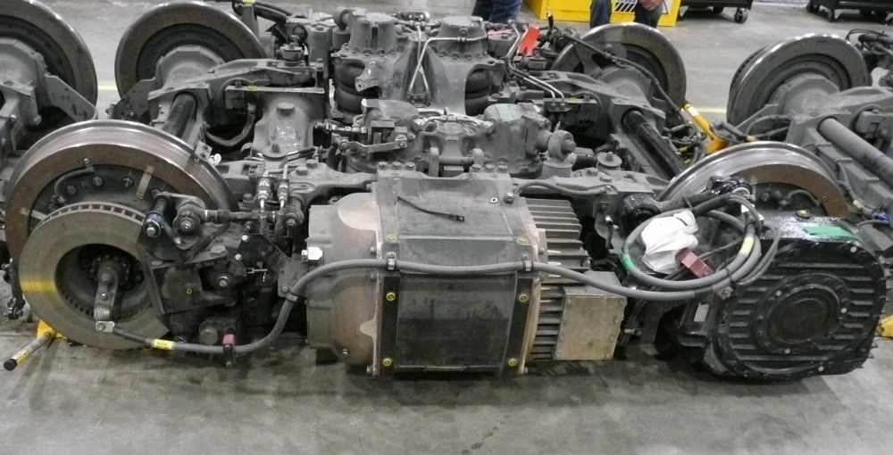
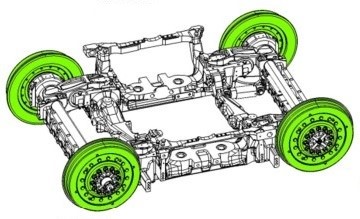
The OLRT purchase of the Citadis Spirit was Alstom’s first North American LRV order. Most of the LRVs for the for stage 1 of the OLRT initial were assembled at the OLRT shop, in Ottawa, where the LRV car bodies were mounted on Iponam bogies. Each LRV is equipped with 5 bogies in total, which includes 3 motor bogiesFootnote 2 (Figure 2) and 2 trailer bogies. Each bogie was equipped with 4 resilient wheel assemblies manufactured by Lucchini RS Group (Lucchini).Footnote 3
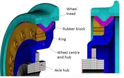
The resilient wheels used for commuter passenger LRVs are fundamentally different from the solid cast steel wheels that are press-fit onto an axle used in freight car service. Each resilient wheel consists of a steel wheel tread, a rubber block, a steel ring and a steel wheel centre with an integrated wheel hub. The components are bolted together to build the wheel (Figure 3). This wheel design is typical for LRVs and has been in sevice since the late 1990s.
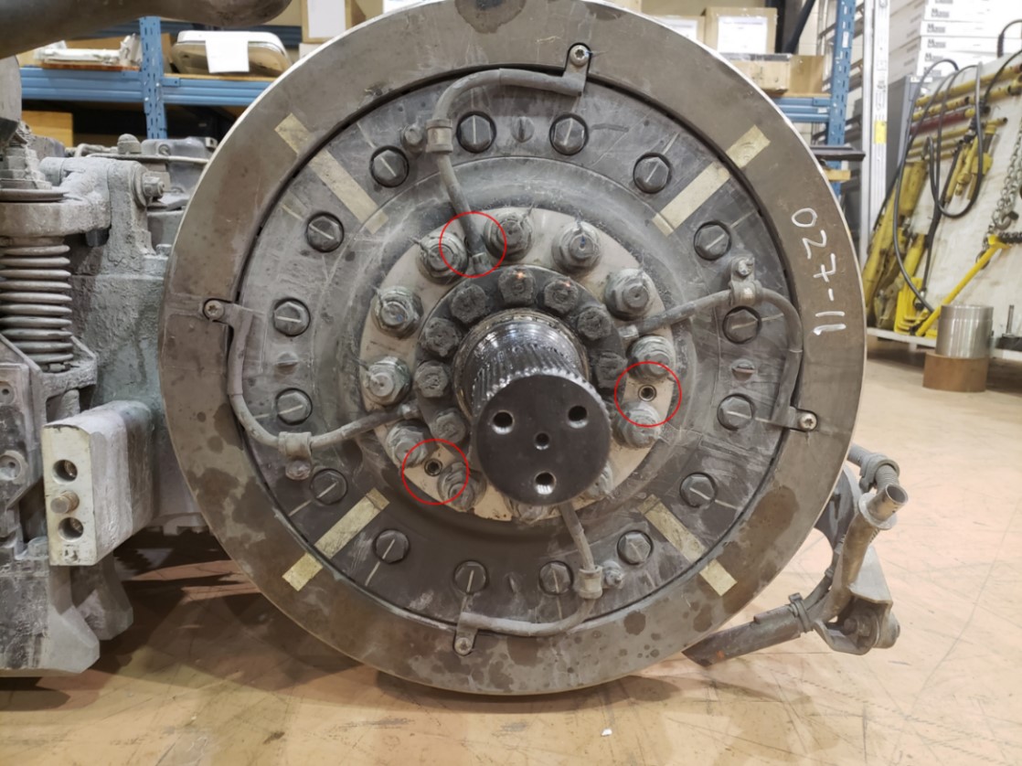
Each wheel hub contains 12 larger holes—1 for each of the 12 axle lug bolts. Similar to an automobile, the LRV resilient wheel assemblies are mounted and secured to bogie axle hubs with lug nuts (Figure 4). During installation, each of the 12 lug nuts seat against the outboard face of the wheel hub and is secured to the axle hub lug bolts with 400 foot-pounds of torque.
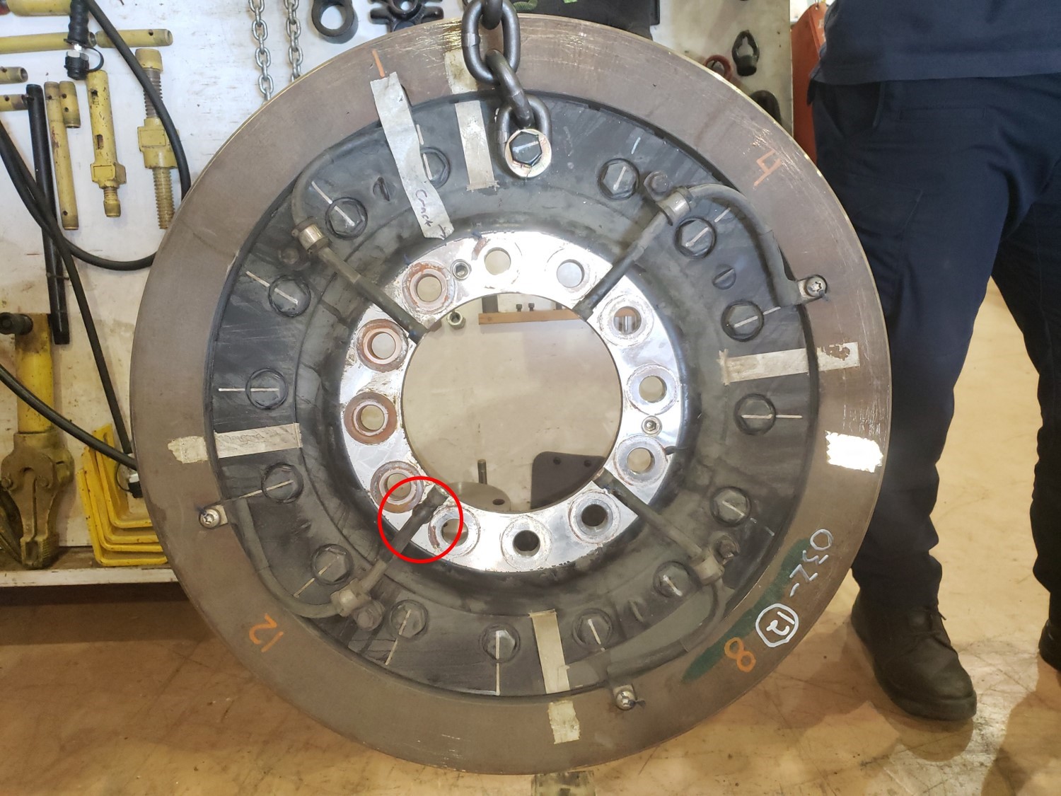
Besides the 12 lug bolt holes, each wheel hub contains 4 grounding cables and 3 smaller threaded holes to accommodate jacking screws. To remove a wheel from the axle, the lug nuts are removed then jacking screws are applied and push against the axle hub in order to separate the wheel hub from the axle hub. One jacking screw location on each wheel is usually obscured by a grounding cable (Figure 5).
Each Lucchini resilient wheel is manufactured and assembled in a European plant. Once assembled, the wheels are packaged together in groups of 4, in wooden crates and then shipped all over the world for installation.
Although resilient wheels have an estimated service life of about 330 000 km, after approximately 100 000 km of service, Alstom proactively determined that a bogie retrofit program was required for the OLRT LRV fleet in order to address some maintenance issues.
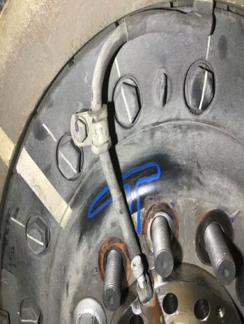
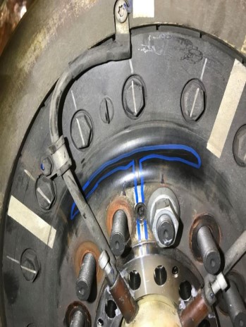
On 02 July 2020, LRV 1113 motor bogie 3 (BM3) was undergoing retrofit at the Alstom facility in Sorel-Tracy, Quebec. During the retrofit, Alstom personnel observed that the wheels located in the L17 and R20 positions had cracks on the outboard face of the wheel hub (Figures 6 and 7).
The incident was reported to the TSB and a TSB investigation commenced (TSB Occurrence R20H0070). Alstom issued a safety alert and, in conjunction with OLRT, implemented a daily inspection of each LRV wheel before the LRV was permitted to enter service. The daily inspection regime identified 4 additional resilient wheels with cracks observed in the outboard surface of the wheel hub. A summary of the cracked wheels identified to date is contained in Table 1.
| Date crack reported | Method of detection | LRV No. | Bogie | Axle | Wheel position | Mileage (km) |
|---|---|---|---|---|---|---|
| 02 July 2020 | Bogie retrofit | 1113 | Motor bogie 3 | I | L17 | 124 000 |
| 02 July 2020 | Bogie retrofit | 1113 | Motor bogie 3 | J | R20 | 124 000 |
| 03 July 2020 | Daily inspection | 1108 | Motor bogie 1 | A | L1 | 108 000 |
| 03 July 2020 | Daily inspection | 1133 | Motor bogie 2 | F | R12 | 122 000 |
| 11 Aug 2020 | Daily inspection | 1114 | Motor bogie 1 | A | R2 | N/A |
| 18 Aug 2020 | Daily inspection | 1128 | Motor bogie 2 | E | L9 | N/A |
The bogies with cracked wheels identified from LRVs 1108, 1133, 1114 and 1128 were subsequently sent to the TSB laboratory for teardown examination and failure analysis. Concurrently, preliminary finite element analysis performed by Alstom suggested that jacking screws that protruded from the rear surface of the wheel hub may have contributed to the development of the wheel hub cracks.
It was reported that all the resilient wheels for the OLRT LRVs were shipped to Alstom from the manufacturer, Lucchini, with jacking screws already installed in the wheels. This was a change in process and was the first time that resilient wheels were shipped with jacking screws installed. Prior to the OLRT LRV build, Lucchini resilient wheels were shipped with plastic plugs or silicone installed in the jacking screw holes to protect the threads. The plugs were removed only when there was a need to use jacking screws to remove a wheel. It appears that the change in process was implemented with no requirement for the wheel manufacturer (Lucchini), the LRV builder (Alstom), or the personnel installing the wheels on the bogies to examine the rear surface of the wheel hub to ensure that none of the jacking screws protruded or otherwise interfered with the mating surface of the axle hub.
To date, Alstom and the TSB have examined all the new Alstom resilient wheel stock and identified that 116 of the 185 new wheels examined (62.7%) had 1 or more jacking screws protruding from the rear surface of the wheel hub.
The TSB has completed the teardown of the 2 bogies from LRV 1108 and LRV 1133 and detailed examination of 4 resilient wheels that exhibited cracks. For examination purposes and to aid with identification, jacking screws were labeled as A, B or C. Jacking screw C is obscured by a grounding strap while jacking screws B and A are labeled counter clockwise from there. Results are contained in Table 2 below.
| LRV & bogie Nos. | Wheel No. | Wheel serial No. | Wheel mfg date | Jacking screw | Visible crack | Low lug nut torque | Measured protrusion | Measured hub deflection | Suspect crack | ||
|---|---|---|---|---|---|---|---|---|---|---|---|
| (in) | (mm) | (in) | (mm) | ||||||||
| LRV 1133 Motor bogie 2 S/N: 032 | R12 wheel 1 crack reported | LE1600514-40 | 06-16 | A | Y | Y | 0.0372 | 0.9449 | -0.0175 | -0.4445 | N/A |
| B | Y | Y | 0.0148 | 0.3759 | -0.0020 | -0.0508 | N/A | ||||
| C* | Y | Y | 0.0232 | 0.5893 | -0.0042 | -0.1067 | N/A | ||||
| LRV 1108 Motor bogie 1 S/N: 037 | L1 wheel 1 crack reported | LE1703671-105 | 02-18 | A | Y | Y | 0.0208 | 0.5283 | -0.0078 | -0.1981 | N/A |
| B | N | Y | 0.0123 | 0.3124 | -0.0018 | -0.0457 | Y | ||||
| C | N | Y | 0.0105 | 0.2667 | -0.0018 | -0.0457 | Y | ||||
| R2 wheel No crack reported | LE1702908-59 | 01-18 | A | N | N | 0.0000 | 0.0000 | 0.0000 | 0.0000 | N | |
| B | Y | Y | 0.0195 | 0.4953 | -0.0060 | -0.1524 | N/A | ||||
| C | N | Y | 0.0150 | 0.3810 | -0.0025 | -0.0635 | Y | ||||
| R4 wheel No crack reported | LE1703671-124 | 03-18 | A | N | N | 0.0000 | 0.0000 | 0.0000 | 0.0000 | N | |
| B | N | N | 0.0040 | 0.1016 | -0.0001 | -0.0025 | Y | ||||
| C* | Y | Y | 0.0185 | 0.4699 | -0.0047 | -0.1194 | N/A | ||||
* Denotes a wheel hub crack that was not initially identified and was obscured by a grounding cable.
With regards to cracking in the area of the resilient wheel hubs, cracks were confirmed in the 2 wheels that were originally reported to have cracks, LRV 1133 R12 and LRV 1108 L1. Furthermore:
- For LRV 1133:
- Although the R12 wheel was reported to have 1 crack, additional visible cracks were observed in the area of all 3 jacking screws (A, B and C).
- The crack observed in the area of jacking screw C was obscured by a grounding cable (Figure 8).
- For LRV 1108:
- The L1 wheel hub was reported to have 1 crack that was visible in the area of jacking screw A.
- Although no crack was reported for the R2 wheel, 1 crack was visible in the area of jacking screw B.
- Although no crack was reported for the R4 wheel, 1 crack was visible in the area of jacking screw C, which was also obscured by a grounding cable.
- For the 12 jacking screws examined:
- 10 had measured protrusions from the rear surface of the wheel hub. In each of these cases, the axle hub exhibited a corresponding indentation from contact with a jacking screw.
- 6 exhibited visual cracking on the front of the wheel hub.
- In each of the 6 cases, the lug nuts positioned on either side of the jacking screw had low torque removal values.
- 4 of the jacking screws that did not exhibit cracking on the front of the wheel hub had other risk factors that suggested that a crack could be present and that further non-destructive testing is required.
The TSB investigation continues and will include 2 additional bogie teardowns, wheel material evaluation, failure analysis of all wheels in which cracks are identified as well as a review of maintenance activities and other potential influences. It is likely that other factors also contributed to the development of the cracks observed in the resilient wheel hubs.
Although ongoing daily inspections by OLRT maintenance staff are being observed, the preliminary TSB examination results demonstrate that some wheel hub cracks may go undetected and the development of cracks in the area of jacking screws installed in the hub of resilient wheels may be more widespread than initially thought. Therefore, it is suggested that OLRT and Alstom expedite the removal of all Lucchini resilient wheels that were originally installed on the OLRT LRV fleet and were equipped with jacking screws.
The TSB would appreciate being advised of OLRT’s position on this matter, and what action, if any, will be taken in this regard.
Upon completion of the investigation into occurrence R20H0079, the Board will release its investigation report.
Yours sincerely,
Original signed by
Paul Treboutat
Director, Investigations, Rail/Pipeline
CC.
-
Director General
Rail Safety
Transport Canada -
Vice President
Operations – Canada
Alstom Transport -
General Manager
Transit Services
City of Ottawa -
Chief Safety Officer
Safety, Compliance, Training and Development
Transportation Services
City of Ottawa
Background information
Occurrence No.
- R20H0079

