Table of contents
1.0 Introduction
1.1 Description of occurrence
1.1.1
On 06 July 2013, shortly before 0100 Eastern Daylight Time, eastward Montreal, Maine & Atlantic Railway freight train No. 2, which had been parked unattended for the night at Nantes, Quebec, started to roll uncontrolled. The train travelled a distance of about 7.2 miles, reaching a speed of 65 mph. At about 0115, while approaching the centre of the town of Lac-Mégantic, Quebec, 63 tank cars carrying petroleum crude oil, UN 1267, and 1 box car derailed. As a result of the derailment, about 6 million litres of petroleum crude oil spilled. There were fires and explosions, which destroyed 40 buildings, 50 vehicles and the railway tracks at the west end of Megantic Yard. A total of 47 people were fatally injured.
1.1.2
Preliminary examination of the derailment site determined that buffer box car CIBX 172032, immediately behind the locomotive consist, and the following 63 loaded tank cars derailed on the main track of a 4.25° right-hand curve in the direction of travel (eastward), covering a No. 11 turnout. The locomotive consist separated from the derailed cars and split into 2 portions, with each travelling different distances before they came to a stop. After a significant time, the front portion of the locomotive consist moved backward (westward) and collided with the second portion, both moving a short distance further (westward) and coming to a final stop together.
1.1.3
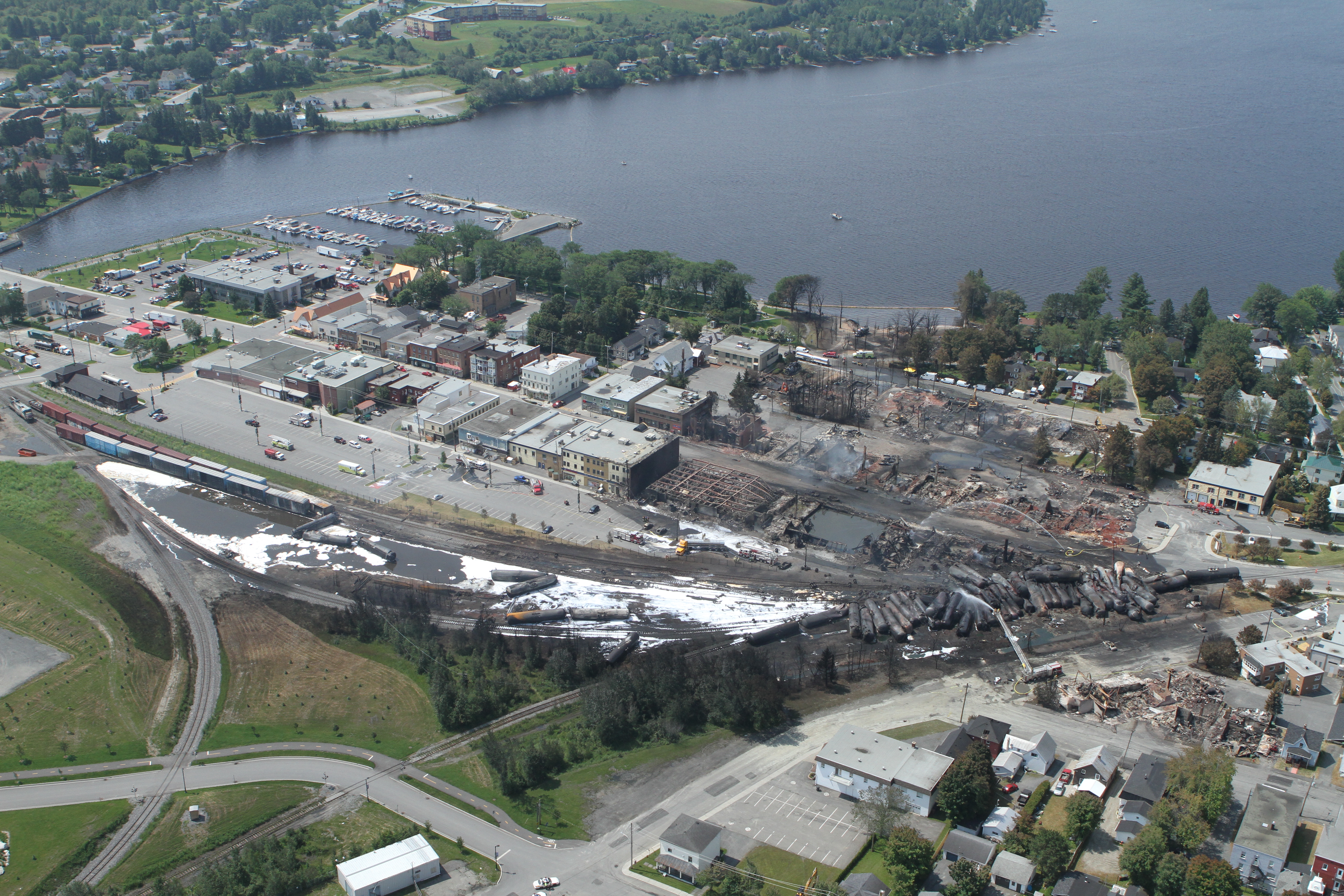
The derailed buffer box car struck a stationary cut of cars on the siding track. The following 8 tank cars were scattered in separated jackknifed positions. The next 2 tank cars lay in the direction of the turnout siding, ahead of the main jackknifed pile-up of the rest of the derailed tank cars among which the fire and explosions occurred. The last 9 tank cars in the train did not derail. They were disconnected and removed back and away from the derailment and fire by the locomotive engineer and emergency responders. An aerial-view photograph of the accident site is shown in Figure 1.
1.2 Background
1.2.1
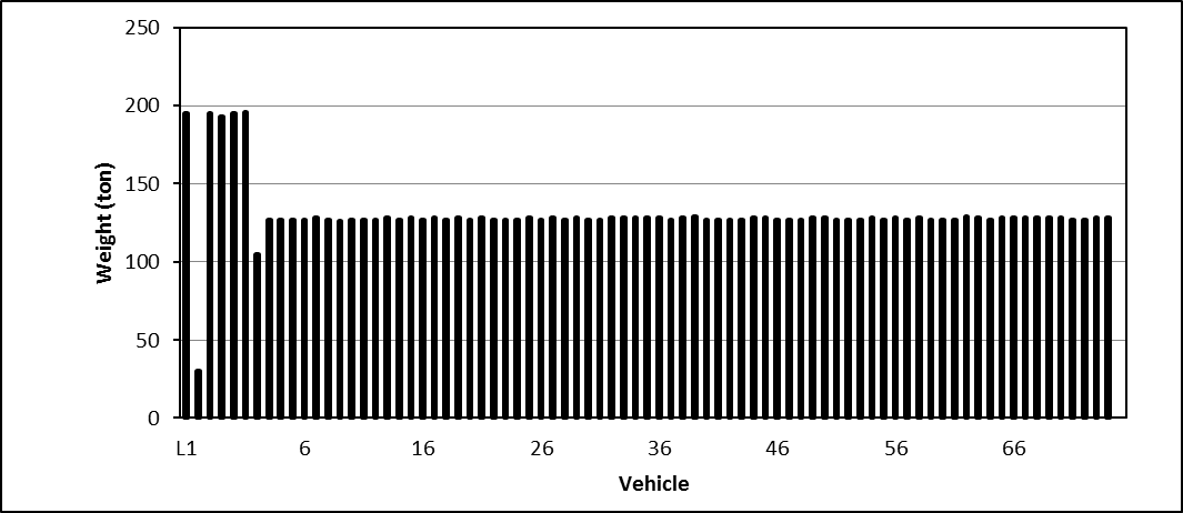
Train MMA-002 consisted of 5 locomotives, 1 operation control car VB-1, 1 loaded buffer box car, and 72 tank cars loaded with petroleum crude oil. The train weighed 10 287 tons and was 4701 feet long. The train weight profile is shown in Figure 2.
1.2.2
The train was operated by a 1-person crew. Before midnight, it came to a stop on the main track of Station Nantes with an automatic application of the air brakes. The locomotive engineer applied hand brakes on the locomotive consist and the buffer car, and then released the automatic brake, but kept the independent brake (IND) of the locomotive consist in the applied position. The engine of the lead locomotive, MMA 5017, was kept running at idle to maintain the air brake supply. The locomotive engineer left the train and went to a hotel for rest, as indicated in his schedule.
1.2.3
A fire was detected on the lead locomotive sometime after the locomotive engineer left (LP181/2013). Local firefighters came and put out the fire. A local MMA engineering employee was called to attend to the fire site. The engine of the locomotive was shut down, and the train was left unattended again. Approximately 59 minutes later, the train started to move down the descending grades, and accelerated all the way until it reached the town of Lac-Mégantic, where it derailed.
1.2.4
The lead locomotive, MMA 5017, was equipped with a Quantum Engineering Incorporated (QEI) locomotive event recorder (LER) version no. S45E, serial no. 0204100033. The recorded data in the “extend log” was downloaded from MMA 5017 by a MMA staff member soon after the accident and provided to the TSB.
1.2.5
The train was also equipped with an end-of-train (EOT) sense and brake unit (SBU). The SBU was sent to the TSB Engineering Laboratory for examination (LP 132/2013). The records in the DataFlash were extracted and converted into Excel spreadsheets. The EOT SBU download data were provided for a comprehensive analysis of LER and SBU data together.
1.2.6
The TSB investigation team also obtained a copy of the standard report of the public crossing at Mile 117.11, Moosehead Subdivision, that indicated the activation of the crossing signal and protection. The time record was calibrated by an independent crossing company. This record was used as a reference in the synchronization and calibration of the downloaded LER time records. The comprehensive analysis of the downloaded LER records, SBU data and the standard report of the public crossing at Mile 117.11 was conducted and a number of significant events of interest were identified to assist the investigation (LP136/2013).
1.3 Engineering services requested
1.3.1
The preliminary investigation found that the train experienced a number of events, including unattended parking, fire, engine shutdown, runaway, derailment, and explosion. There were several broken knuckles, including those between the second and third locomotives, indicating that the locomotive consist had separated and rejoined. The derailed cars were scattered in several small, jackknifed groups as well as in a main pile-up. The final positions of the derailed cars and the LER data analysis suggested that the point of derailment (POD) was likely located around the west end switch on the 4.25° right hand curve. The excessive centrifugal force due to the high speed (65 mph at the derailment) may have caused or contributed to the derailment.
1.3.2
A laboratory project was opened for calculation of the lateral force and the rollover speed at the POD curve. The preliminary calculation indicated that the derailment speed was lower than the rollover speed due to the pure centrifugal force on the curve for the derailed tank cars. A further simulation was conducted to obtain the longitudinal in-train force at the derailment moment and the corresponding transformed lateral force. The combination of the centrifugal force and the transformed lateral force of the in-train buff force could cause the derailment if the couplers and the tank car were in jackknifed position.
1.3.3
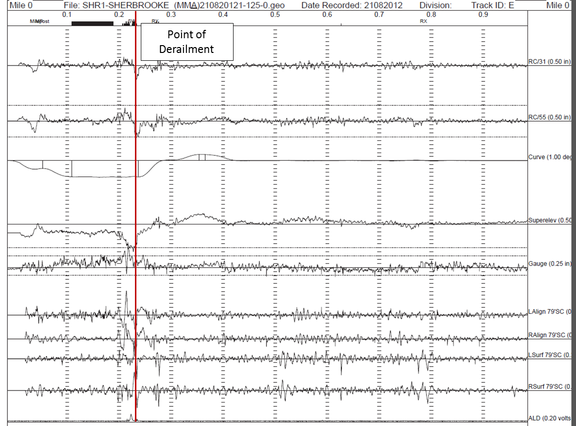
Subsequently, the investigation team obtained the latest track geometry car test records in form of brush charts dated 21 August, 2012 which showed some significant geometry irregularities near the switch. These track geometry defects might generate significant dynamic forces and contribute to the derailment. However, the digital data of the track geometry record charts was not available and the track geometry state on the day of occurrence was not known as the track was destroyed in the accident. It is not possible to determine the exact effect of the track geometry condition and the resulting dynamic force quantitatively.
1.3.4
The TÜV Rheinland Mobility Inc. Rail Sciences Division (TRRSI) was contracted to conduct a VAMPIRE vehicle/track dynamic simulation to evaluate the effect of the track geometry. A generalized tank car model developed by TRRSI was used. As the track and derailed cars were destroyed, it was not possible to obtain the actual wheel and rail profiles of the first derailed car at the POD. Standard AAR wheel and rail profiles were used in the simulation.
1.3.5
This LP report describes the calculation of the centrifugal force on the curve caused by the high speed, the simulated in-train force at the derailment moment, the available track geometry records and VAMPIRE simulated dynamic response. The analysis of the combination of the centrifugal force, the dynamic forces generated by the track geometry and the in-train force helps to identify and explain the most likely derailment scenario and the contributions of the factors.
2.0 Centrifugal force and roll over speed at POD curve
2.1 Equilibrium speed and superelevation
2.1.1
Curved tracks are normally elevated by an amount (superelevation) depending on curvature to provide a lateral force balance at a given speed. The superelevation is the height, in inches, that the outer (high) rail of a curve is elevated above the inner (low) rail. It is intended to balance the effect of centrifugal force.
2.1.2
The weight of the vehicle, acting downward vertically from the vehicle’s center of gravity (CG), is added to centrifugal force to create a resultant force as shown in Figure 3:
- A resultant force that passes through the track centerline indicates balanced elevation and the weight of the vehicle will be distributed equally between the high and low rails.
- A resultant that passes to the inside of track centerline indicates over-balanced elevation.
- A resultant that passes to the outside of the track centerline indicates under-balanced elevation.
2.1.3
The equilibrium speed on a curve is the speed at which the resultant of the weight and the centrifugal force is perpendicular to the plane of the track. The relationship is
where
is degree of curvature (100-foot chord)
is train speed, mph
2.1.4
The MMA requires that the maximum allowable operating speed for each curve must not produce an underbalance in excess of 1 ½ inches unless authorized by the System Office of Engineering. The maximum speed will be computed using the following formula:
where
is actual elevation of the outer rail, inches
is underbalance, inches
is degree of curvature
2.1.5
The average superelevation in the 4.25° curve located from Mile 0.05 to Mile 0.28 was about 1 ½ inches, corresponding to a balanced speed of 22 mph. Typically, for freight trains negotiating this degree of curvature with the superelevation that existed, train speed should not exceed 32 mph (assuming a maximum of 1 ½ inches of underbalance).
2.2 Lateral forces on curve
2.2.1
A rail vehicle travelling on a curved track at a speed generates a centrifugal force, as shown in Figure 3. The centrifugal force can be calculated as:
where
is the gravity acceleration or gravitational constant, 32.16 ft/s/s
is the speed at curve, feet/sec
is the radius of curve, in feet
is the degrees of curve
2.2.2
The centrifugal force acts at the center of gravity of the vehicle in the lateral outward direction and transmits to the wheel/rail interface. The elevation on the curve transforms a portion of the vehicle weight into a lateral inward force .
where
is the superelevation, inches
is the track width between rail centers, approximately 59 inches.
2.2.3
The net lateral force on the entire car is the balance of the centrifugal force and the lateral portion of weight due to elevation.
2.2.4
The vertical forces on the outer rail and the inner rail are respectively
where is the height of center of gravity of vehicle above rail top, in inches
2.2.5
The lateral force of the entire vehicle on the outer rail is
where is coefficient of friction between wheel tread and rail top
2.2.6
The lateral forces of a truck side, a wheel on the outer rail and an axle are approximately,
truck side
wheel
axle
2.2 Rollover speeds at POD curve
2.3.1
Vehicles may roll over outward on curves at high speeds because of excessive centrifugal force, as shown in Figure 3. The critical condition occurs when the compound force resulting from the centrifugal force and the gravity force points to the high (outer) rail so the low (inner) wheel will be lifted from the low rail. Under the critical condition, the following equation exists:
where
is the track width between rail centers, inches
is the height of center of gravity of vehicle above rail top, in inches
2.3.2
The critical rollover speed can be calculated as
3.0 Simulation of in-train force
3.1 Train dynamic model and parameters
3.1.1
A longitudinal dynamic model of a train consists of any combination of a number of different locomotives and a large number of different cars. Only one locomotive (normally the lead one) takes operational control, while the other locomotives, which can be located anywhere within the train, will act according to the control orders from the control locomotive. Cars are passive bodies subject to dynamic rules and application of traction, dynamic brake (DB) and air brake forces according to the response output of their air brake systems with respect to trigger times and air pressures.
3.1.2
Every vehicle, including the locomotives and cars, is modeled as a rigid body with a mass and length that is supported vertically by trucks and wheel axles, with a draft gear at each end of the body, and connected by a pair of couplers between the draft gears of the adjoining vehicles according to the train consist.
3.1.3
The parameters for each vehicle include:
- order number (from the front to the rear of the train),
- mass (or weight),
- tare weight (light weight, for calculation of brake force),
- length,
- longitudinal location X0 of the front end at simulation start time,
- air brake system type and parameters (braking ratio, friction coefficient etc.), for each car,4
- front draft gear type/initial position,
- rear draft gear type/initial position, and
- ratio of air pipeline length to vehicle length.
3.1.4
Additional parameters for locomotives include:
- traction force chart by throttle levels and speed,
- dynamic braking force chart by DBN and speed, and
- independent braking force state (bail on/off).
3.1.5
Conditions and parameters for the whole train include:
- operation activities in time or mileage series (throttle levels, dynamic braking, emergency braking, brake air pressure, bail independent brake etc.).
- track grades in mileage series.
- track curvatures in mileage series.
- initial speed and acceleration (time history as a reference), and
- other initial and boundary conditions.
3.2 Dynamic equilibrium equations and solution
3.2.1
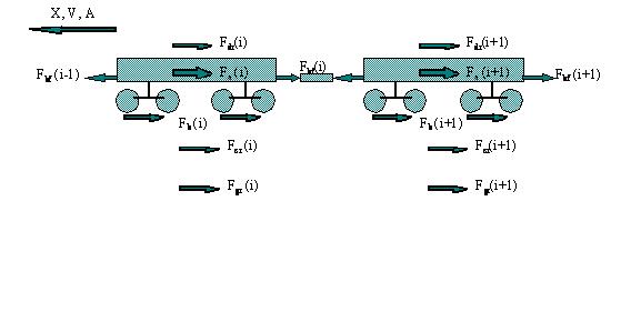
A model of a sample vehicle in the train with all applying forces is shown in Figure 4, and its dynamic equilibrium equations are established according to mathematics and dynamics rules.
3.2.2
Forces acting on each vehicle include:
- inertia forces (acceleration times mass) ;
- air brake forces (on each vehicle as a whole, the output of its air brake system with a trigger time and propagation distance) ;
- drawbar forces or in-train force (function of relative displacement and velocity of the adjoining vehicles) or ;
- drag resistance including air resistance (function of speed) and adjust resistance ;
- curve resistance (function of speed, curvature) ; and
- grade resistance (function of grade) .
3.2.3
Among the above forces, air brake forces and drawbar forces are the most complex functions involving multiple non-linear parameters. It is conventional and more convenient to model them as black box subsystems, and to establish their detailed models in respective libraries of air brake systems and draft gear systems. For each type of air brake subsystem, or pair of draft gears, a sub model is used to establish a nonlinear input-output function.
3.2.4
Additional forces on locomotives include:
- DB forces (function of speed and DB level, given by locomotive manufacturers, or from LER records), and
- traction forces (function of speed and throttle levels, given by manufacturers, or from LER records).
3.2.5
Dynamic equilibrium condition: The dynamic equilibrium of all forces was established for each vehicle and assembled for the whole train by setting the draft gear force between the adjoining vehicles the same.
3.2.6
Friction limit condition: All braking or traction forces on a vehicle could not exceed the maximum friction force determined by the friction between wheel and rail, , where is friction coefficient and is the tare weight.
3.2.7
Boundary conditions: The drawbar force of the front draft gear of the lead locomotive, and that of the rear draft gear of the last vehicle were zero, , where is the total number of vehicles in the train including locomotives.
3.2.8
Initial condition: A set of designated values were set up at the start moment for the system variable vectors to run a designated procedure.
3.2.9
Dynamic differential equations for the longitudinal location of the front end (or center) of each vehicle at time were established. The equations are nonlinear second order differential equations.
3.2.10
A number of direct time integration algorithms were available to solve the nonlinear differential equations. The integration time step is an important parameter that requires careful selection in order to reach a stable and accurate solution.
3.2.11
Other associated variables that can be calculated and outputted from the solved basic variables are:
- dynamic displacement, velocity, and acceleration/deceleration of each vehicle,
- drawbar force at each draft gear (distribution along the train),
- maximum drawbar force in the train,
- brake distance,
- energy consumption, and
- propagation of air braking along the train line
3.3 Coupler/draft gear elements
3.3.1
The coupler/draft gear elements between adjoining vehicles are one of the two most complex nonlinear elements (the other is the air brake elements) in train dynamics models. Adjoining vehicles are connected by the coupler/draft gear elements that consist of a coupler and a draft gear from each of the two adjoining vehicles. The coupler is regarded as a rigid body and its mass is ignored, while the draft gear possesses a nonlinear relationship between the draft gear relative movement and its reaction force.
3.3.2
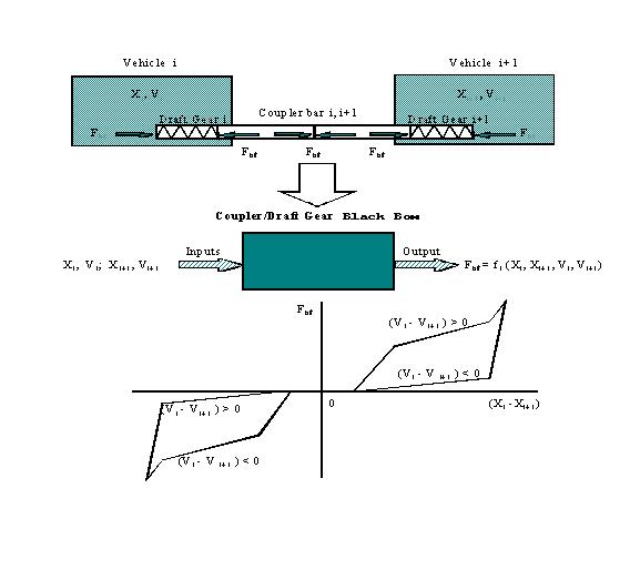
As the couplers are connected and the forces on each of them are equal, the coupler/draft gear elements between two adjoining cars can be modeled separately or as a whole system converted into a black box with a compound nonlinear relationship between the inputs (relative movement of the adjoining vehicles) and the output (the equal drawbar force or coupler force), as shown in Figure 5.
3.3.3
These black box elements can be established according to the actual pair of draft gears that are involved in the coupler/draft gear subsystem between the adjoining vehicles. The pair of draft gears from the adjoining vehicles might be identical or of different types. The conventional and most efficient method for modeling of black box elements is to establish a library of black box models corresponding to the commonly used draft gears.
3.4 Air brake systems
3.4.1
Air brake elements are another type of nonlinear, complex elements in train dynamics models. Similarly we can model them by nonlinear black box elements. The relationship between the input and output is also compound nonlinear, but could be simplified as a series of linear sections.
3.4.2
Air brake application or in-train initiated emergency (UDE) air braking are initiated and the brake signal propagates along the train. In the UDE case, after the UDE signal arrives in the locomotives, the train information and braking system (TIBS), if equipped, initiates the end of train (EOT) emergency braking with an approximate 2 second delay.
3.4.3
At each vehicle in the train, once the air brake signal arrives, the brake pipe pressure (BP) starts to drop and reaches zero. Then brake cylinder pressure ( ) starts to build up and reaches the maximum level in a time . The pressure pushes the brake shoes to apply a brake shoe force on the wheel. The retarding braking force can be expressed as:
where
is the weight
is the coefficient of friction
is the brake cylinder air pressure
3.4.4
The pressures at the vehicles in the train are calculated based on the locations of the vehicles, initiation origin and mechanism, braking signal propagation rate along the train and build up time, . With the TIBS system and activation delay, the emergency braking could be initiated from both the locomotives and the EOT to reduce the propagation time and build up along the train in a shorter time. This also helps reduce braking force differences and in-train forces due to the propagation delay.
3.5 Drag resistance
3.5.1
Drag resistance force on a train includes air resistance, which is a function of speed, and friction resistance, such as that of roller bearings and wheel/track interface. Experiments have shown that drag resistance force is proportional to the weight of vehicles or train.
3.5.2
The drag resistance coefficient is expressed as resistance per unit weight. Several tests have resulted in experimental formulas to calculate the unit drag resistance, among which the Davis equation [1][2] is most commonly used:
Where
is weight per axle in tons
is weight of the vehicle in tons
is train speed in mph
is the cross section area in square feet of the vehicle
, are experimental coefficients in Table 6.2 in [1]
is an adjustment factor
3.6 Curve and grade resistance
3.6.1
Extra resistance occurs on curves and applies forces to the train. Curve resistance force is also a function of the weight of the vehicles.
3.6.2
The curve resistance coefficient is about 0.8 lb/ton/degree based on tests.
3.6.3
Extra forces are applied to a train when it runs on a grade slope. In the travel direction, a descent grade will add a grade force forward, and an uphill grade will add additional resistance force. The grade force is proportional to the weight of the vehicles and the grade.
3.6.4
The grade force, is assumed to be a resistance so sign (grade) takes a positive value for an uphill grade and a negative value for a descent grade in the travel direction. The coefficient is 20 lbs/ton/percent grade.
3.7 Special conditions
3.7.1
The simulation focused on the runaway of Train MMA-002 up to the derailment moment. Only residual independent (IND) air brake was applied on the locomotives and hand brakes were applied on the locomotive consist and the buffer box car. This condition simplified the simulation.
3.7.2
The LER system recorded the runaway started when the IND dropped to 27 psi and the derailment occurred when the IND dropped to 16 psi and the train speed reached 65 mph. The track grades and curvatures were estimated from the track profile diagram in Figure 6 and Figure 7. The difference between the model and the actual train was expressed by the adjustment factor to the drag resistance , which was determined by comparison of the simulated speed and the LER records in the most likely case, and this adjustment factor was applied to all simulation cases.
3.7.3
The simulated in-train force distribution along the train at the derailment moment is plotted in Figure 8. The maximum in-train force appeared at car No. 10 from the train head end which located at the transition from grade 1.2% to the nearly flat terrain. The front tank cars (No. 3 to No.10 in train consist) at the highest in-train forces were located at the vulnerable section of the switch on the curve where the POD and main pile-up were observed.
3.8 Transformed lateral force and ratio
3.8.1
Longitudinal in-train force, is transformed into lateral force at the drawbar whenever the couplers take an angle against the longitudinal central line of the car body, called coupler angle or drawbar angle. The transformed lateral force is proportional to the sine of the drawbar angle .
3.8.2
When a train is in compression or buff state, particularly in a zigzag or jackknifed position, the drawbar angle can reach its maximum with the couplers pushing against the side of the housing. Longitudinal forces can be transformed into large lateral forces which can impact the truck and be transmitted to the rail. Excessive transformed lateral force can cause different types of derailments [3][4] depending on the positions of the involved cars and couplers and the track resistance. If the lateral ballast resistance against tie movement (panel shift) is stronger than the fastening constrain against rail rollover, the transformed lateral force can cause a car rollover, wheel climb or rail rollover derailment. Otherwise, it can cause track panel shift and lead to a different type of derailment.
3.8.3
If the car is in a horizontal alignment position as shown in Figure 9, the transformed lateral force at the drawbars of the car ends produce lateral force acting on the truck .
3.8.4
If the car is in a horizontal zigzag or jack-knifed position shown in Figure 10, the transformed lateral force at the drawbars of the car ends produce lateral force acting on the truck , which is times a ratio of car length over truck centre .
3.8.5
The transformed lateral force , at the truck can change the vertical forces on the rails. As the transformed lateral force acts at the coupler height above the rail top, the truck side vertical forces are changed into:
3.8.6
In a case that a truck rolls over the rail or a wheel climbs the rail, the wheels on the truck side rolling over the rail push the rail with the flanges while the wheels on the other side sit on top of rail without flange contact. The truck side lateral force that causes rail roll over equals minus the friction force on the top of the rail on the other side,
where
is the friction coefficient between the wheel tread and the rail top
3.8.7
With the simulated in-train buff force , the transformed truck side lateral force and ratio can be calculated by the above formulas. A friction coefficient of 0.315 was used in the calculations to cover the speed range of simulation.
3.8.8
Under high centrifugal force and buff in-train force, the two wheels of a truck side are more likely pushed against the rail evenly by the transformed lateral force from the truck center. Therefore, the transformed wheel ratio and truck side ratio are likely equal and the wheel lateral force is likely half of the truck side lateral force .
4.0 VAMPIRE vehicle/track dynamic simulation
4.1 Track geometry irregularities
4.1.1
As prescribed by the Track Safety Rules (TSR), the main track was last visually inspected by a track maintenance employee in a hi-rail vehicle on 05 July 2013. During that inspection, no exceptions were noted in the area of the derailment.
4.1.2
The track was tested annually for rail flaws and geometry defects. The last continuous testing for internal rail defects was performed on 19 September 2012. No results were obtained between Mile 46.00 and Mile 0.00, including the derailment area.
4.1.3
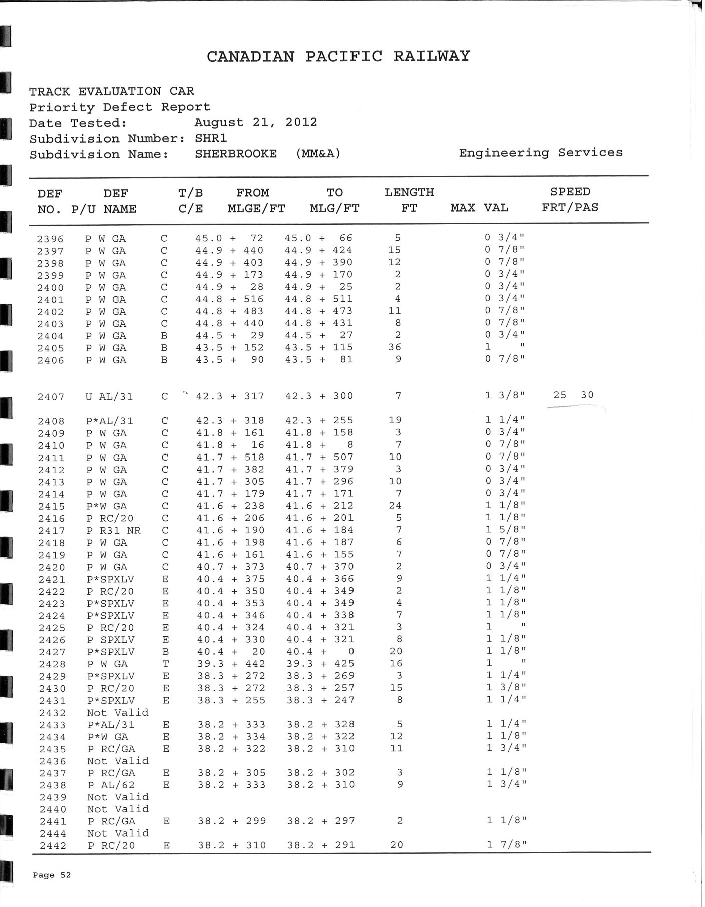
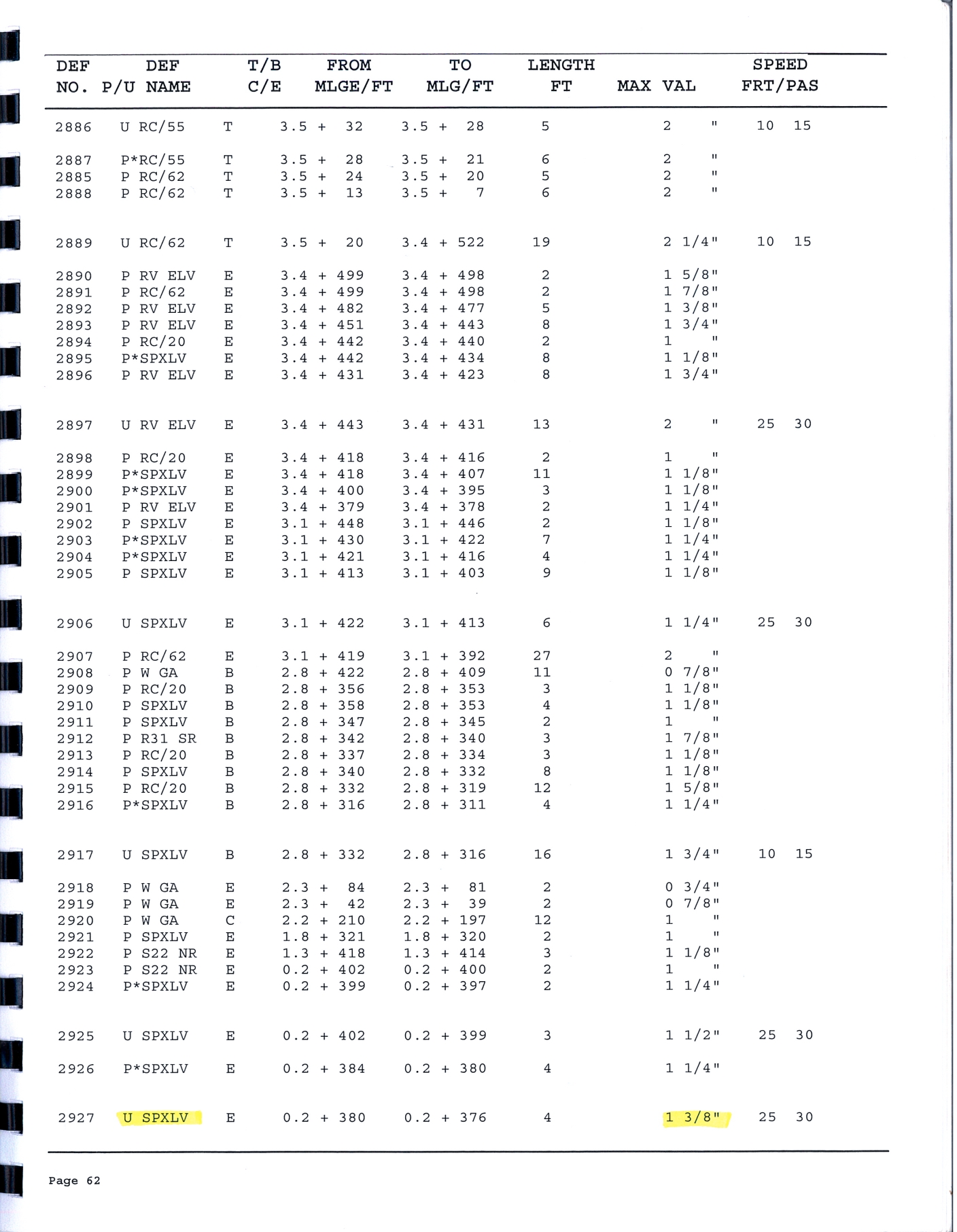
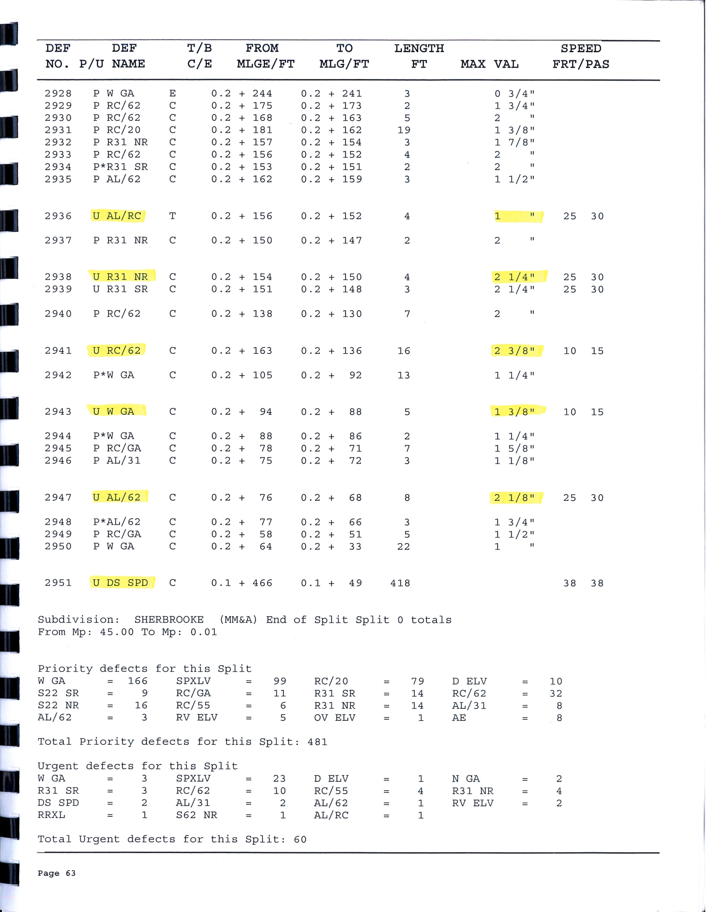
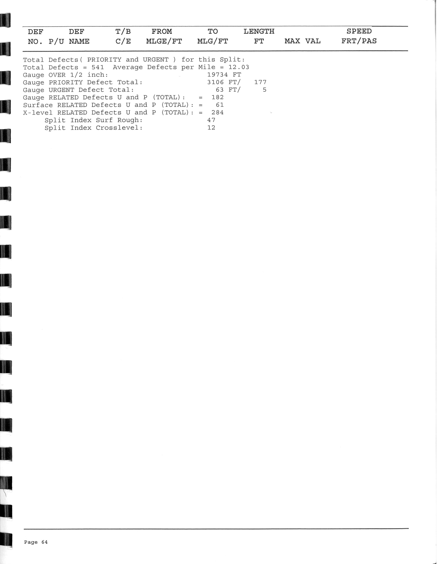
A track evaluation car performed a track geometry inspection on 21 August 2012. The inspection car generated a brush chart as shown in Figure 11. In the immediate area of the Frontenac public grade crossing and the Megantic West main-track turnout, the inspection identified several urgent defects related to spiral cross-level, alignment/rate of change, wide gauge, misalignment and design speed (see Appendix A). The photo of the track section approaching the switch in Figure 12 also showed a depressed rail joint and corresponding geometry defects. Minor repairs were made to improve track conditions; however, no permanent repairs were made, and a temporary slow order was put in place.
4.1.4
The historic Transport Canada inspection records of the curve and turnout section and the TSB post derailment examination of the track sections over approximately 30 miles on either side of the town of Lac-Mégantic observed excessive rail wear, loose track components and other defects. For example, on 24 July 2012, a TC Safety Officer inspected the main track between Mile 0.00 and Mile 42.00 of the Sherbrooke Subdivision and the Officer observed that the frog, guard rail and heel bolts were loose for the turnout at Megantic West. On 14 May 2013, a TC Safety Officer observed that the fastenings at the same turnout were not intact or maintained. Other recurring defects that were noted included corrugated, battered rail joints, crushed head rail (deformation) and ballast missing at various locations.
4.1.5
The track at the POD was destroyed in the accident and its condition on the day of the occurrence could not be determined. There was no digital data file available corresponding to the track inspection brush charts. No track geometry data was available to allow a detailed and accurate vehicle/track dynamic simulation to quantitatively evaluate the effect of the track geometry. However, it is reasonable to assume that the recurring defects corresponding to the battered rail joint in front of the switch very likely existed on the day of occurrence. As the speed limit around the curve was very low, the track geometry condition could have been at low level.
4.1.6
Based on the railway dynamics knowledge and industrial experience, track geometry defects at urgent or priority level could generate significant dynamic forces and a derailment risk. If the track geometry defects around the POD as shown in Figure 11 recurred, they could generate high transient dynamic forces. On the day of occurrence, the dynamic effects of the track geometry defects were added to the lateral force and unloading from the centrifugal force and the in-train force, contributing to the derailment. There is no doubt that the combination of the three factors induced the high lateral force and unloading that caused the derailment.
4.1.7
The previous sections have accurately calculated the contributions of the centrifugal force and in-train force. The centrifugal force or the in-train force alone was not sufficient to cause the derailment, and the combination of the centrifugal force and the in-train force under the all alignment train condition was still not enough to cause the derailment. But the combination of the centrifugal force and in-train force under coupler jack-knifing condition could generate high lateral force and unloading that would impose a derailment risk.
4.1.8
Though the track geometry data on the day of occurrence was not available, the brush chart from the latest track geometry inspection on 21 August 2012 could be used as a reference data to estimate the possible effect of track geometry in a nominal VAMPIRE vehicle/track dynamic simulation.
4.2 Vehicle/track dynamic model
4.2.1
The VAMPIRE vehicle dynamics simulations were conducted to investigate the effects of track geometry and in-train force at coupler action on vehicle/track interaction of a model of a tank car similar to those involved in the Lac-Megantic derailment.
4.2.2
The vehicle and track were modeled based upon the information collected by the TSB investigation team. The coupler forces were applied to the car body of the tank car model in accordance to the force magnitudes and coupler angles determined in the previous sections.
4.2.3
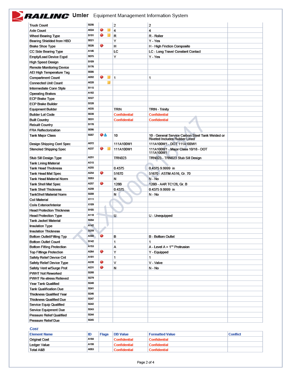
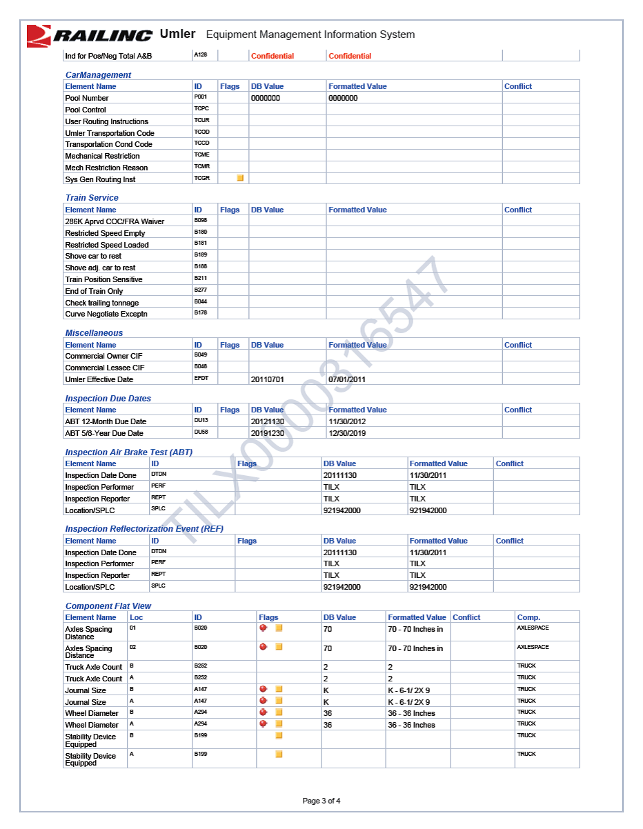
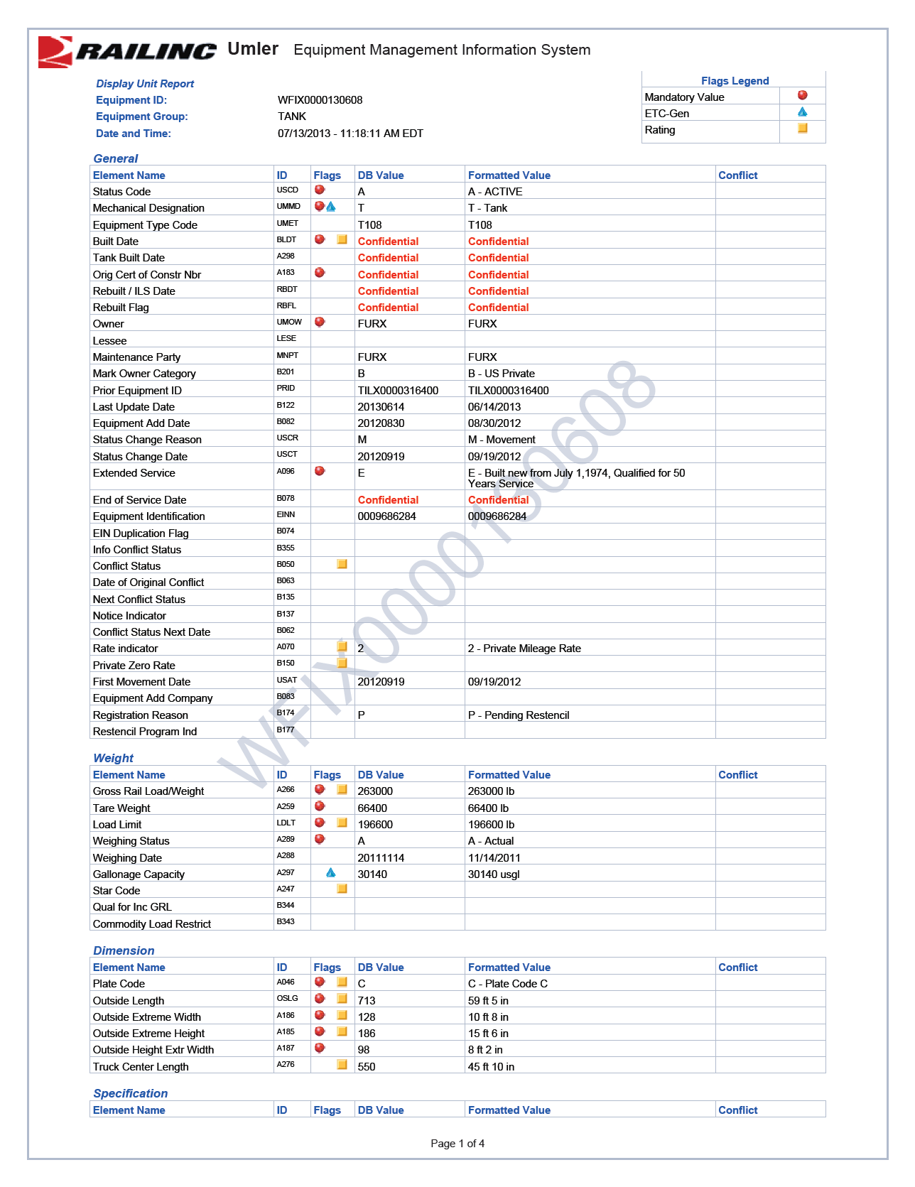
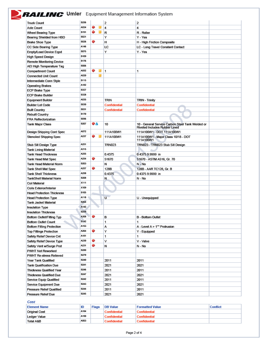
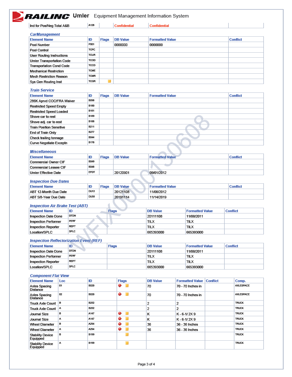
The tank car model was created based upon the UMLER, center of gravity and weight data collected from the sample tank cars TILX0000316547 and WFIX0000130608. The UMLER files are included in Appendix B.
4.2.4
The following summarizes some of the pertinent features for the tank car model:
- Car body center of gravity height above top of rail = 91”
- Total vehicle weight = 128 tons
- Truck center distance = 45’ 10”
- Axle spacing = 70”
- Wheel diameter = 36”
- Long travel constant contact side bearings
- AAR 1B WF wheel profile
- AREA 115 rail profile
4.2.5
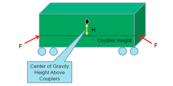
The coupler forces of 100 kips buff force at the two different coupler angles were broken down into equivalent lateral forces and roll moments and applied to the car body CG in simulations involving coupler forces as in Figure 13. This resultant lateral force is negative and the roll moment is positive with respect to the VAMPIRE coordinate system when traversing a right hand curve.
4.2.6
The resultant lateral force and roll moment applied to the car body center of gravity are calculated and listed in Table 1 at two coupler angles, 1.26 degrees and 9 degrees, the minimum and maximum on the curve, corresponding to the aligned and jack-knifed coupler position. But the car body was assumed in aligned position.
| Coupler Force (kip) | Coupler Height (in) | Car Body CG Height (in) | Car Body CG Height above Couplers (in) | Coupler Angle (degrees) | Total Lateral Force Applied at CG (lb) | Total Roll Moment Applied at CG (lb-in) |
|---|---|---|---|---|---|---|
| 100 | 34.5 | 91 | 56.5 | 9 | 31287 | 1767708 |
| 100 | 34.5 | 91 | 56.5 | 1.26 | 4398 | 248480 |
Note: All forces and moments were constantly applied onto the car body CG |
||||||
4.2.7
The vehicles were traveling in the direction of descending milepost with respect to the provided brush chart images in Figure 11. The point of derailment occurred at the location indicated on a right hand curve, approximately 4.25 degrees, in the direction of travel. Points were read off the charts in the direction of descending milepost at increments of approximately 16.5 feet (0.1 mile divided by 32).
4.2.8
The following data was read at each increment:
- Curvature
- Super Elevation
- Gauge
- Left Alignment
- Right Alignment
- Left Surface
- Right Surface
4.2.9
The read points were processed into channels of a VAMPIRE Irregularity file using the following relationships:
- Distance = Distance
- Cross Level = Superelevation
- Curvature = Curvature
- Lateral Irregularity = Average of Left Alignment and Right Alignment
- Vertical Irregularity = Average of Left Surface and Right Surface
- Gauge = Gauge
4.2.10
Positive and negative was reversed for the curvature and superelevation data points with respect to the datum lines of the brush chart as the direction of travel was in descending mileposts and a right hand VAMPIRE sign convention was used.
4.2.11
Other measurements’ sign convention were unchanged relative to the zero line on the charts provided. The values above the datum were considered positive while values below the datum were considered negative.
4.2.12
The simulations started through a 1000 feet tangent track with no track geometry irregularities to minimize the transient effect of the applied constant in-train force, then went into the curved track section approaching to the POD. The POD is at distance 2189 for the VAMPIRE track files created from the brush charts.
4.3 Simulation case design
4.3.1
Seven simulation cases were designed and performed to investigate the effects of the three contribution factors and their combinations. An additional case was conducted to assess a low speed at which the resultant forces would not cause derailment. The simulation results were compared with the previous calculations of steady state centrifugal force and transformed lateral force from the in-train force. The analysis of the results and differences between the cases identified the effects and roles of the factors on the derailment. The conditions and parameters of the 8 simulation cases are listed in Table 2.
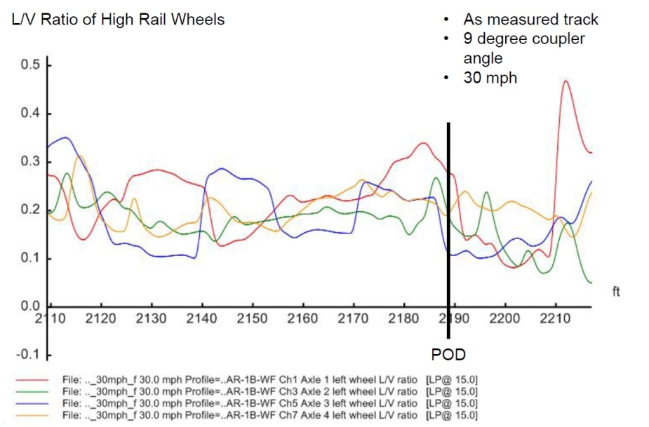
| Case | Speed | Track Condition | In-train Force | Coupler Angle |
|---|---|---|---|---|
| 1 | 65 | As Measured from the Brush Charts | 100 kips Buff | 9 degrees |
| 2 | 65 | As Measured from the Brush Charts | 100 kips Buff | 1.26 degrees |
| 3 | 65 | As Measured from the Brush Charts | None | NA |
| 4 | 30 | As Measured from the Brush Charts | 100 kips Buff | 9 degrees |
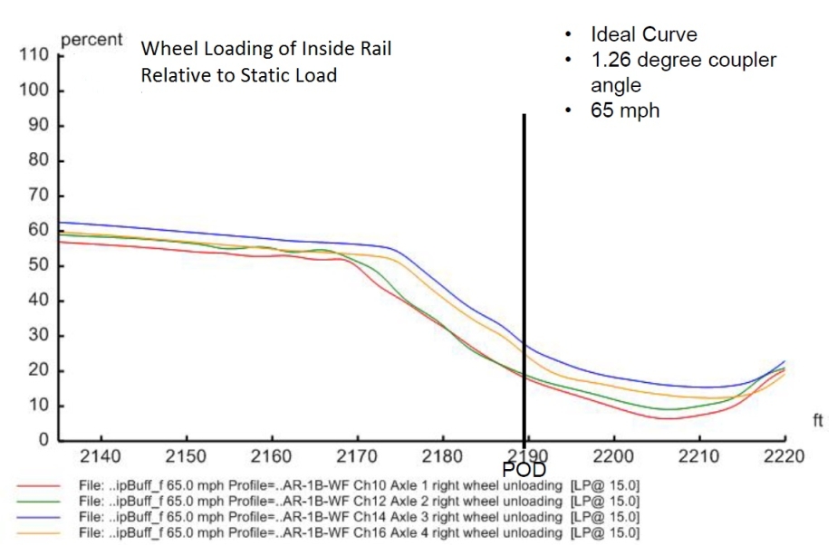
| 5 | 65 | Ideal 4.25 Degree RH Curve with 1.5" Superelevation | 100 kips Buff | 9 degrees |
| 6 | 65 | Ideal 4.25 Degree RH Curve with 1.5" Superelevation | 100 kips Buff | 1.26 degrees |
| 7 | 65 | Ideal 4.25 Degree RH Curve with 1.5" Superelevation | None | NA |
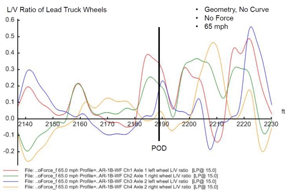
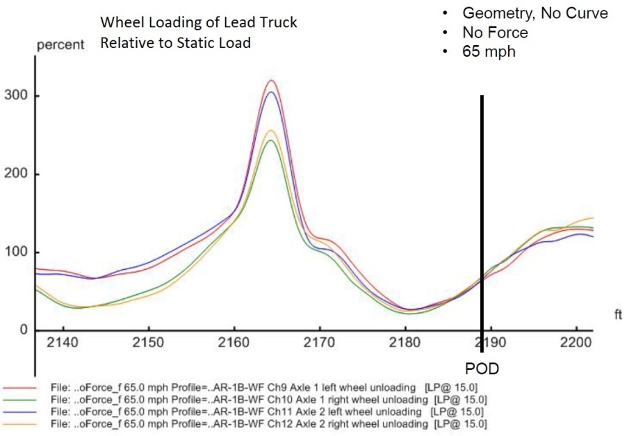
| 8 | 65 | As Measured from Brush Charts but No Curvature | None | NA |
4.3.2
Case 1 to 3 would identify the most likely derailment scenarios of three factors and the effect of the in-train force and coupler angle. Case 4 would show the comprehensive effect of the speed compared with Case 1. Case 5 to 7 would show the effect of the in-train force and coupler angle on the ideal 4.25 degree curve. Comparison between Case 1 to 3 and Case 5 to 7 respectively would show the difference caused by the measured track geometry on the curve. Case 8 would demonstrate the dynamic response of the track geometry irregularities solely on tangent track.
4.3.3
The lateral and vertical dynamic forces from all wheels were output and the derailment related indicators such as wheel ratios, unloading percentage, axle sum ratios and truck side ratios were output in statistic form. Spread sheet files for the basic statistic outputs for each of the simulations shown above are included in Appendix C. Reported results were filtered with a 15 Hz 4 pole low pass filter. These statistic outputs are centered around the reported POD and will be analyzed in next section.
5.0 Analysis
5.1 Rollover speeds
5.1.1
The LER data analysis and derailment site survey indicated that the suspected first derailed cars were the loaded tank cars among cars No. 3 to No.10 in the train consist. If the train speed exceeded or was close to the rollover speed of the vehicle on the curve, the first derailment might be caused purely by the centrifugal force in the form of car rollover at the POD on 4.25° right hand curve (R = 1348 feet) with an average elevation of 1 1/2 inches (a maximum local elevation of 3 5/8 inches was detected in the track geometry inspection on 21 August, 2012). The heights of the center of gravity of the loaded tank cars were between 88.8 inches and 91 inches, as recorded in the UMLER data. The height of the center of gravity of the involved locomotives was approximately 72 inches. The rollover speeds for the tank car with the low and high center of gravity and the locomotives are calculated and listed in Table 3.
| Parameters\Vehicle | Tank Car A | Tank Car B | Locomotives | |
|---|---|---|---|---|
| Curvature | degrees | 4.25° | 4.25° | 4.25° |
| Radius | feet | 1348 | 1348 | 1348 |
| Superelevation | inches | 1 ½ | 1 ½ | 1 ½ |
| Track width | inches | 59 | 59 | 59 |
| Elevation | rad | 0.0254 | 0.0254 | 0.0254 |
| CG height | inches | 88.8 | 91 | 72 |
| CG | rad | 0.3207 | 0.3135 | 0.3889 |
| Total | rad | 0.3461 | 0.3389 | 0.4143 |
| Rollover | ft/s | 123.10 | 121.69 | 135.92 |
| Rollover | mph | 83.9 | 83.0 | 92.7 |
Note: Gravity acceleration g = 31.16 ft/s/s |
||||
5.1.2
The calculated rollover speeds due to centrifugal force on the curve for the involved tank cars and locomotives are significantly higher than the derailment speed of 65 mph. This difference indicates that the centrifugal force on the curve at 65 mph alone could not roll over the vehicles as long as the track was intact.
5.2 Lateral forces from centrifugal force
5.2.1
Though the centrifugal force alone was insufficient to roll over the vehicles on the curve at the derailment moment, it induced a large lateral force on the vehicles that caused vertical load shift to unbalance and increased lateral force onto the outer rail side while the vertical load on the inner rail was reduced. It is essential to calculate and examine the lateral forces from the centrifugal force against the track resistance.
5.2.2
The calculated lateral forces from the centrifugal force are listed in Table 4. Tank Car A represents the lowest CG height and Tank car B represents the highest CG height. The induced truck side, wheel and axle lateral force were within the track strength, and the unloading percentages (65%-67% for the tank cars and 53% for the locomotives) were in the acceptable range. The ratio was very low as the lateral force and vertical force increased simultaneously. This further indicated that the centrifugal force alone would not cause the derailment if the track was intact.
| Parameters\Vehicle | Tank Car A | Tank Car B | Locomotive | Comment | |
|---|---|---|---|---|---|
| CG height | in | 88.8 | 91 | 72 | entire car |
| lb | 55382 | 55382 | 84371 | entire car | |
| lb | 6508 | 6508 | 9915 | entire car | |
| lb | 48873 | 48873 | 74455 | entire car | |
| lb | 44646 | 42581 | 92039 | entire car | |
| lb | 211354 | 213419 | 297961 | entire car | |
| lb | 34810 | 35460 | 45463 | entire car | |
| lb | 17405 | 17730 | 22731 | truck | |
| lb | 8702 | 8865 | 7577 | truck | |
| lb | 12218 | 12218 | 12409 | truck | |
| 0.16 | 0.17 | 0.15 | entire car | ||
| 0.19 | 0.19 | 0.19 | entire car | ||
| lb | 83354 | 85419 | 102961 | entire car | |
| % | 65 | 67 | 53 | entire car | |
5.3 Simulated in-train force
5.3.1
The vehicles in the runaway train were subjected to the similar centrifugal forces at the same speed at the derailment moment, but the front portion of the train including the locomotive consist and a few cars passed the POD without derailing. This observation confirmed that the centrifugal force alone was not sufficient to roll over the vehicles. There must have been some other factors contributing to the derailment. In-train force was a very likely factor. The train had the residual independent brake and hand brake on the locomotive consist and the buffer box car applied and ran on a descending grade approaching the POD curve which was located on a near flat track section. A significant in-train buff force was inevitable at the track section at the derailment moment.
5.3.2
The measured residual IND and hand brake force (LP187/2013) were used in the simulation and calculations. The train dynamics simulation obtained the distribution of in-train buff force along the train at the derailment moment as shown in Figure 8. The highest in-train forces appeared among car No.3 to No. 10 that were located around the POD section at the LER recorded derailment moment. The simulated in-train buff forces at these vehicles of interest are listed in Table 5a, Table 5b, Table 5c and Table 5d. The simulated in-train forces were approximately 100 to 110 kips at the cars of interest. The in-train force in this range was not unusual.
| Vehicle | (lb) | (lb) | (lb) | (%) |
|---|---|---|---|---|
| Last Loco | 86983 | 1913 | 4666 | 2.4 |
| Car #3 | 96373 | 2119 | 5168 | 4.1 |
| Car #4 | 98136 | 2158 | 5263 | 4.1 |
| Car #5 | 99899 | 2197 | 5359 | 4.2 |
| Car #6 | 101662 | 2235 | 5451 | 4.3 |
| Car #7 | 103436 | 2275 | 5549 | 4.3 |
| Car #8 | 105199 | 2313 | 5641 | 4.4 |
| Car #9 | 106950 | 2352 | 5737 | 4.6 |
| Car #10 | 108713 | 2391 | 5832 | 4.6 |
Note:
|
||||
| Vehicle | (lb) | (lb) | (lb) | (%) |
|---|---|---|---|---|
| Last Loco | 86983 | 3027 | 7383 | 3.8 |
| Car #3 | 96373 | 2747 | 6700 | 5.3 |
| Car #4 | 98136 | 2798 | 6824 | 5.4 |
| Car #5 | 99899 | 2848 | 6946 | 5.5 |
| Car #6 | 101662 | 2897 | 7066 | 5.6 |
| Car #7 | 103436 | 2949 | 7193 | 5.6 |
| Car #8 | 105199 | 2998 | 7312 | 5.8 |
| Car #9 | 106950 | 3049 | 7437 | 5.9 |
| Car #10 | 108713 | 3100 | 7561 | 6 |
Note:
|
||||
| Vehicle | (lb) | (lb) | (lb) | (%) |
|---|---|---|---|---|
| Last Loco | 86983 | 13607 | 33188 | 16.9 |
| Car #3 | 96373 | 15076 | 36771 | 29 |
| Car #4 | 98136 | 15352 | 37444 | 29.5 |
| Car #5 | 99899 | 15628 | 38117 | 30 |
| Car #6 | 101662 | 15903 | 38788 | 30.5 |
| Car #7 | 103436 | 16181 | 39466 | 30.8 |
| Car #8 | 105199 | 16457 | 40139 | 31.6 |
| Car #9 | 106950 | 16731 | 40807 | 32.4 |
| Car #10 | 108713 | 17006 | 41478 | 32.7 |
Note:
|
||||
| Vehicle | (lb) | (lb) | (lb) | (%) |
|---|---|---|---|---|
| Last Loco | 86983 | 21531 | 52515 | 26.8 |
| Car #3 | 96373 | 19544 | 47668 | 37.5 |
| Car #4 | 98136 | 19902 | 48541 | 38.2 |
| Car #5 | 99899 | 20260 | 49415 | 38.9 |
| Car #6 | 101662 | 20616 | 50283 | 39.6 |
| Car #7 | 103436 | 20976 | 51161 | 40 |
| Car #8 | 105199 | 21334 | 52034 | 41 |
| Car #9 | 106950 | 21689 | 52900 | 42 |
| Car #10 | 108713 | 22046 | 53771 | 42.3 |
Note:
|
||||
5.4 Transformed lateral forces from in-train force
5.4.1
The transformed lateral force from the in-train force depends on the positions of the couplers and car-body. If the train was in theoretical alignment, all the couplers and car bodies would be in aligned position, the coupler angles would be the minimum and the transformed lateral force would be the minimum. However, as recent studies (Ref 3, 4) and investigation experiences showed that, under coupler jackknifing condition, the coupler angle could reach its maximum limit under the buff force due to the positive feedback mechanism, and in-train buff force can be transformed into significant lateral force and contribute to derailment.
5.4.2
There could be four different combinations of coupler and car-body positions: a) both coupler and car-body in alignment position, b) coupler in alignment but car-body in jackknifed position, c) coupler in jack-knifed position but car-body in alignment position, and d) both coupler and car-body in jack-knifed position. Scenario a) generates the minimum coupler angle and transformed lateral force, and scenario d) generates the maximum coupler angle and transformed lateral force.
5.4.3
On the derailment curve of 4.25°, the equal length of the tank cars, 59 feet 5 inches, would cover a circle angle of approximately 2.52°. If the couplers were in alignment position, the coupler angle would be half of the circle angle, i.e. 1.26°. If the couplers were in a jack-knifed position under buff in-train force, the positive feed-back mechanism could push the coupler angle to the maximum angle. For the E type couplers on the tank cars, the maximum coupler angle would be 9°.
5.4.4
If the car-body was in aligned position, the transformed lateral force at each truck center would be equal to that at the coupler. But if the car was in a jack-knifed position, the transformed lateral force at the truck center would be amplified by a ratio of the car length over the truck center distance. The transformed lateral forces at truck center and the unloading DV on the inner rail under the four position scenarios are calculated and also listed in Table 5a, Table 5b, Table 5c and Table 5d.
5.4.5
The transformed lateral forces acted at the coupler height above the rail top, different from the centrifugal force that acted at the center of gravity. The transformed lateral force also induced a vertical load shift that led to an unloading on one side while overloading on the other rail. The unloading percentages from the in-train force alone were far below the safety limit.
5.5 Combination of centrifugal force and in-train force
5.5.1
The runaway train was subjected to the combination of the centrifugal force and the in-train buff force at the derailment moment. The resulting combined lateral forces and unloading are calculated and listed in Table 6.
5.5.2
The combined lateral force and unloading closely depend on the coupler and car-body positions. If no coupler was jack-knifed, the coupler angle would be very small on the curve (approximate 1.26 degrees). The transformed lateral force would be minor. The combined lateral force and unloading would still be in the relatively safe range. Therefore the additional dynamic force generated from the track geometry would be the necessary to cause the derailment.
5.5.3
If any coupler went into jack-knifed position under the buff in-train force in Position c and d as per paragraph 5.4.2, the combination of the centrifugal force and in-train force would induce extremely high lateral forces that exceed the track resistance and the inner wheels could be lifted. The cars could derail no matter if the car-body was in aligned or jack-knifed position, as in both positions extremely high lateral forces at the outer (high) rail and unloading at the inner (low) could be generated. Comparatively the jack-knifed car-body position produced higher transformed lateral forces than the aligned car-body position. Under such high lateral forces and unloading percentage, the possible derailment scenarios could be in the form of widening gauge, breaking/deflecting high rail, wheel lift from the low rail and possibly striking the switch point rail.
| Parameters\Vehicle | Tank Car A | Tank Car B | Locomotive | Comment | |
|---|---|---|---|---|---|
| lb | 5168 | 5832 | 4666 | Position a: aligned coupler and aligned carbody |
|
| lb | 88522 | 91251 | 107627 | Position a: aligned coupler and aligned carbody |
|
| % | 69 | 71 | 55 | Position a: aligned coupler and aligned carbody |
|
| lb | 39478 | 36749 | 87373 | Position a: aligned coupler and aligned carbody |
|
| lb | 2119 | 2391 | 1913 | Position a: aligned coupler and aligned carbody |
|
| lb | 1060 | 1196 | 957 | Position a: aligned coupler and aligned carbody |
|
| lb | 18465 | 18926 | 23688 | Position a: aligned coupler and aligned carbody |
|
| lb | 6700 | 7561 | 7383 | Position b: aligned coupler and jack-knifed carbody |
|
| lb | 90054 | 92980 | 110344 | Position b: aligned coupler and jack-knifed carbody |
|
| % | 70 | 73 | 57 | Position b: aligned coupler and jack-knifed carbody |
|
| lb | 37946 | 35020 | 17656 | Position b: aligned coupler and jack-knifed carbody |
|
| lb | 2747 | 3100 | 3027 | Position b: aligned coupler and jack-knifed carbody |
|
| lb | 1374 | 1550 | 1514 | Position b: aligned coupler and jack-knifed carbody |
|
| lb | 18779 | 19280 | 24245 | Position b: aligned coupler and jack-knifed carbody |
|
| lb | 36771 | 41478 | 33188 | Position c: jack-knifed coupler and aligned carbody, wheel lift risk on tank cars |
|
| lb | 120125 | 126897 | 136149 | Position c: jack-knifed coupler and aligned carbody, wheel lift risk on tank cars |
|
| % | 94 | 99 | 70 | Position c: jack-knifed coupler and aligned carbody, wheel lift risk on tank cars |
|
| lb | 7875 | 1103 | 7875 | Position c: jack-knifed coupler and aligned carbody, wheel lift risk on tank cars |
|
| lb | 15076 | 17006 | 13607 | Position c: jack-knifed coupler and aligned carbody, wheel lift risk on tank cars |
|
| lb | 12595 | 16659 | 6804 | Position c: jack-knifed coupler and aligned carbody, wheel lift risk on tank cars |
|
| lb | 30000 | 34389 | 29535 | Position c: jack-knifed coupler and aligned carbody, wheel lift risk on tank cars |
|
| lb | 47668 | 53771 | 52515 | Position d: jack-knifed coupler and jack-knifed carbody, wheel lift on all vehicles |
|
| lb | 131022 | 139190 | 155476 | Position d: jack-knifed coupler and jack-knifed carbody, wheel lift on all vehicles |
|
| % | 100 | 100 | 100 | Position d: jack-knifed coupler and jack-knifed carbody, wheel lift on all vehicles |
|
| lb | -3022 | -11190 | -27476 | Position d: jack-knifed coupler and jack-knifed carbody, wheel lift on all vehicles |
|
| lb | 19544 | 22046 | 21531 | Position d: jack-knifed coupler and jack-knifed carbody, wheel lift on all vehicles |
|
| lb | 19544 | 22046 | 21531 | Position d: jack-knifed coupler and jack-knifed carbody, wheel lift on all vehicles |
|
| lb | 36949 | 39776 | 44262 | Position d: jack-knifed coupler and jack-knifed carbody, wheel lift on all vehicles |
|
Note: Negative values for indicated wheel lift for the vehicles. Subscript 1 for centrifugal force, a-d for in-train force at positions. |
|||||
5.6 VAMPIRE simulation results
5.6.1
The first derailed cars were traveling at 65 mph, much higher than the balance speed of the curve at the superelevation and the speed limit of the section. The cars were inclined to the high rail. The in-train buff force also pushed the cars toward the outside of the curve. The track geometry irregularities generated bouncing and rocking. The most critical derailment related indicators were lateral force and wheel ratios on the high rail, and the unloading on the low (inside) rail. According to AAR Chapter XI, the limit of wheel ratio is 1.0, and the limit of unloading is 90% (or 10% vertical load relative to static load is left). The industry experience takes 20 kips as the risk threshold of the wheel lateral force against the track strength. The truck side and axle sum ratio are the indicators of a similar nature to evaluate the risk of rail rollover and track breaking through. In the following analysis, the discussions focus on the wheel lateral force and wheel ratios on the high rail, and the unloading on the low (inside) rail.
5.6.2
It must be noted that the VAMPIRE vehicle track dynamic simulations were performed on a generalized car model with nominal wheel/ rail profiles, which are sensitive to the results, and the track geometry data was recorded 11 months before the occurrence. The simulation results were qualitative references for estimating the effects of the contribution factors rather than an accurate quantitative reflection of the state on the day of the occurrence. However, these qualitative references were helpful in demonstrating the relative contributions and roles of the three factors in the derailment.
5.6.3
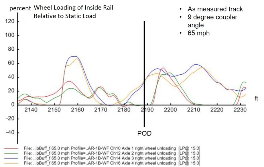
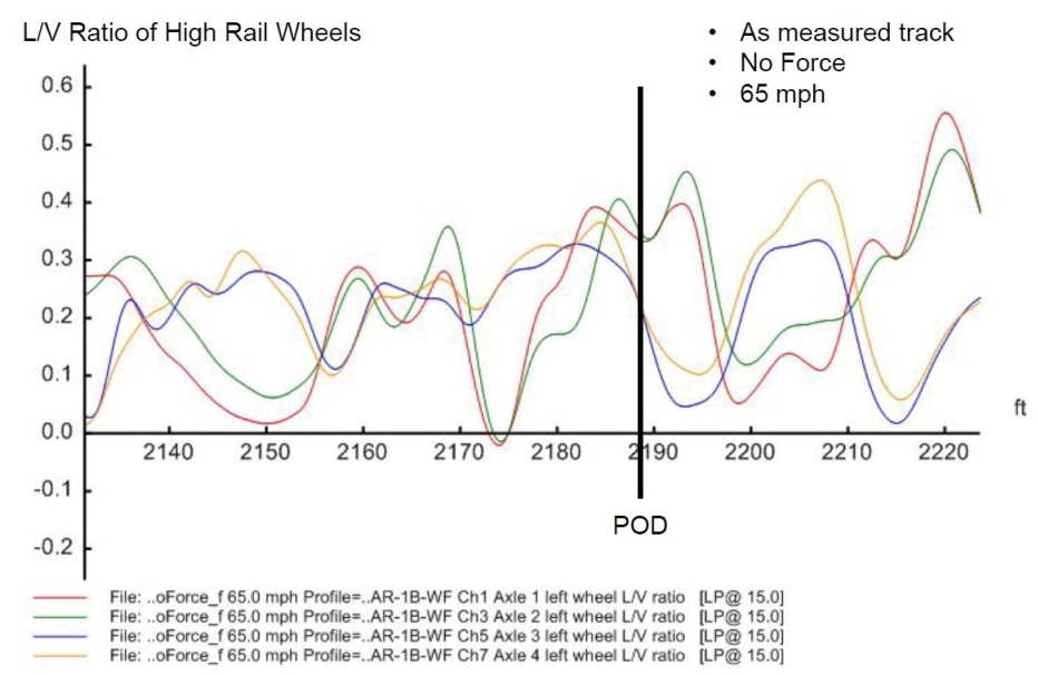
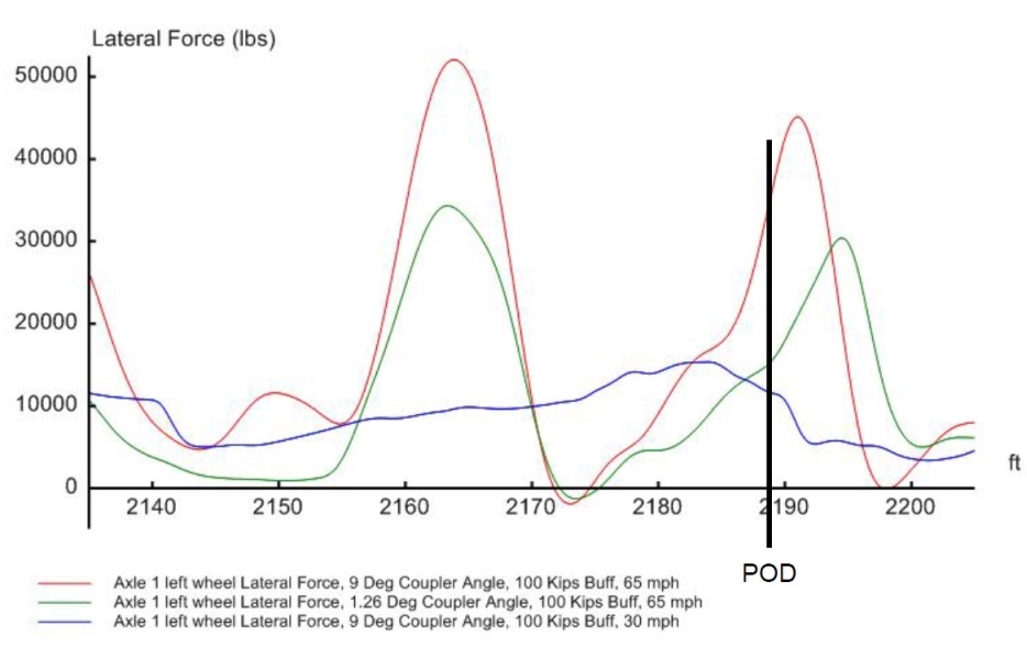
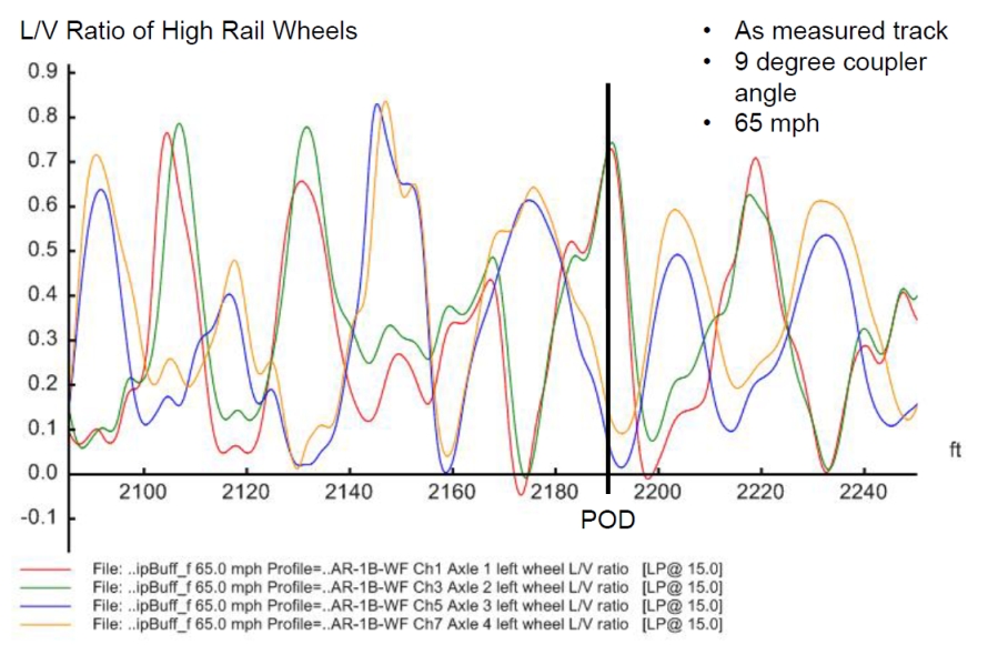
The output derailment indicators around the POD are plotted in Figure 14 to 28 and the statistic results of the 40 foot section centered by the POD are summarized and listed in Table 7. Reported results were filtered with a 15 Hz 4 pole low pass filter. VAMPIRE uses the dynamic loading percentage as the unloading index.
Figures 14 to 28. Output derailment indicators around the POD
| Case | Condition | Wheel | Loading (%) | Lateral Force L (lb) | |||
|---|---|---|---|---|---|---|---|
| mean | max | mean | min | mean | max | ||
| 1 | MeasuredTrack_9DegF100V65 | 0.44 | 0.74 | 14.9 | -1.8 | 23,163 | 47,965 |
| 2 | MeasuredTrack_1p26DegF100V65 | 0.33 | 0.51 | 6.7 | -0.5 | 17,464 | 36,081 |
| 3 | MeasuredTrack_NoForceV65 | 0.31 | 0.45 | 8.6 | -0.9 | 1 5,862 | 29,871 |
| 4 | MeasuredTrack_9DegF100V30 | 0.23 | 0.34 | 63.6 | 55.2 | 9,735 | 15,345 |
| 5 | IdealCurve_9DegF100V65 | 0.39 | 0.40 | 4.8 | -0.0 | 23,769 | 24,541 |
| 6 | IdealCurve_1p26DegF100V65 | 0.28 | 0.31 | 19.0 | 9.8 | 15,537 | 17,662 |
| 7 | IdealCurve_NoForceV65 | 0.25 | 0.29 | 27.0 | 16.8 | 13,505 | 16,602 |
| 8 | TrackGeomOnly_NoCurve_NoFV65 | 0.25 | 0.39 | 78.0 | 21.6 | 5,672 | 12,610 |
Note:
|
|||||||
5.6.4
The mean and max/min values in the ideal curve cases are relatively close to each other respectively, indicating the nature of ideal track geometry that produces small oscillations, as in Figure 22 to 25 (including some effect of the theoretical transition from spiral to curve on the unloading approaching the POD). The measured track geometry produced significant dynamic response, being reflected by the large differences between the mean and the max/min values and shown in the plotted figures. The left wheel ratios in all the cases were below the derailment criterion as the lateral force increased simultaneously as the vertical force did on the high rail from the centrifugal force and in-train force. The derailment unlikely occurred in the form of wheel climbing.
5.6.5
Case 7 on ideal curve with no in-train force at speed 65 mph is the dynamic simulation of the centrifugal force on the ideal curve of 4.25 degrees. Compared with the steady state calculated results in Table 4, the simulated dynamic lateral force, wheel/ ratio and unloading percentage are higher than the steady state calculated results showing the dynamic vibration of the vehicle on even ideal track geometry . All those indicators are below the derailment thresholds, indicating that the centrifugal force alone is not sufficient to roll over the car.
5.6.6
Case 5 and 6 shows the effect of the coupler angle in the combination scenarios of centrifugal force and in-train force. If the couplers were aligned (Case 6, at the minimum angle of 1.26 degrees, equivalent to scenario a in Table 6), the contribution of the in-train force would be minor. If the couplers were jack-knifed to the maximum angle of 9 degrees, the in-train force would significantly contribute to the derailment indicators. The maximum lateral force would exceed the threshold while the loading percentage would reach the criterion (Case 5, equivalent to the position c scenario in Table 6). It is interesting that the simulated unloading around the POD in dynamic Case 5 is very close to the steady state one in Table 6. However, the simulated dynamic lateral force around the POD is much higher than the steady state calculated results. The simulation Case 5 and 6 confirmed that the combination of the centrifugal force and the in-train force might be safe if the couplers and the cars were aligned, but could impose severe derailment risk if the couplers were jackknifed.
5.6.7
All Case 1, 2, 3 and 5 generated negative loading percentages, which indicated complete wheel lift, and excessive lateral forces. The actual derailment scenario must be between Case 1 and 2 with the combination of the three contribution factors. Case 3 shows that even without the contribution of in-train force, the combination of the centrifugal force and the dynamic bouncing/rocking generated by the track geometry at the high speed could be sufficient to cause derailment.
5.6.8
Case 4 clearly shows the critical effect of the speed. If the speed were 30 mph, the contribution from the three factors together would produce the derailment indicators well below the derailment thresholds, and no derailment would occur.
5.6.9
Case 8 demonstrates the contribution from the track geometry irregularities solely. All the simulated derailment indicators in Case 8 are below the derailment thresholds, indicating that the track geometry irregularities alone would not be sufficient to derail the cars even at the high speed of 65 mph.
5.6.10
Comprehensive analysis of the combinations of the three factors determined that the derailment was caused by the combination of the centrifugal force, the dynamic bouncing/rocking generated by the track geometry irregularities and the in-train force. The derailment was inevitable due to the high speed of 65 mph.
5.6.11
Any one of the following factors, centrifugal force, the track geometry irregularities or the in-train force would not be sufficient to cause the derailment.
5.6.12
The centrifugal force due to the high speed at the curve contributed most to the derailment, while the track geometry irregularities and the in-train force were the secondary contributors.
5.6.13
The contribution of the in-train force depends on the positions of the couplers and the cars. If the couplers and cars were aligned, the contribution of the in-train force would be minor. If the couplers were jack-knifed to the maximum angle, the contribution of the in-train force could be significant. The combination of the centrifugal force and the in-train force under coupler jack-knifed position could impose severe derailment risk.
6.0 Conclusions
6.1
The derailment was caused by the combination of the centrifugal force, the dynamic force generated by the track geometry conditions and the in-train buff force. In consideration of these factors, the derailment was inevitable due to the high speed of 65 mph.
6.2
Any one of the following factors, centrifugal force, track geometry irregularities or in-train forces, would not be sufficient to cause the derailment.
6.3
The centrifugal force due to the high speed at the curve contributed most to the derailment, while track geometry irregularities and in-train forces were secondary contributors.
6.4
The rollover speeds due to the centrifugal force on the 4.25° curve were calculated to be approximately 83.0 to 83.9 mph for the derailed loaded tank cars and 92.7 mph for the involved locomotives, at a superelevation of 1 ½ inches.
6.5
The train speed at the derailment moment was significantly below the rollover speeds of the vehicles on the curve, and the lateral forces and unloading from the centrifugal force were within the acceptable range. The centrifugal force alone would not rollover the vehicles to cause the derailment as long as the track was intact.
6.6
The track geometry condition at the POD on the day of occurrence could not be determined quantitatively. If the track geometry defects recurred to the levels noted in the previous inspection, they could generate significantly high dynamic forces, contributing to the derailment.
6.7
The track geometry irregularities alone would not be sufficient to derail the cars even at the high speed of 65 mph.
6.8
Combination of the centrifugal force and the dynamic forces generated by the track geometry at speed of 65 mph could be sufficient to cause derailment.
6.9
The speed is critical to the centrifugal force and the dynamic force generated by the track geometry. At 30 mph, the contribution from the three factors would result in derailment indicators well below the derailment thresholds.
6.10
The simulated in-train buff forces at the derailed tank cars were approximately 100 to 110 kips, which alone would not cause derailment of the loaded vehicles in the occurrence.
6.11
The transformed lateral force and unloading from the in-train force closely depend on the coupler and car-body position. The coupler angle would be small if all couplers and car-bodies were in aligned positions. If any coupler went into jackknifed position under the buff in-train force, the coupler angle could reach the maximum limit allowed by the car’s striker housing.
6.12
If all the couplers and car-bodies were in aligned position and the track conditions were ideal, the contribution of the in-train force would be minor, and the combination of the centrifugal force and the in-train buff force would not be sufficient to cause derailment.
6.13
If any of the couplers was jack-knifed to the maximum angle, the combination of the centrifugal force and the in-train force under coupler jack-knifed position could impose severe derailment risk.
7.0 References
[1]. William H. Hay, Railroad Engineering, John Wiley & Sons Inc; ISBN: 0471364002.
[2]. Paul Rhine, Locomotive Engineering Guide to Fuel Conservation, Simmons-Boardman Books, Inc. 1996; ISBN: 0911382178.
[3]. D. Chen, Derailment Risk due to Coupler Jack-knifing under Longitudinal Buff Force. Proc. IMechE, Part F: J. Rail and Rapid Transit, 2010, 224 (F5), 483-490. DOI 10.1243/09544097JRRT363.
[4]. D. Chen, Contributing Factors and Applicable Criteria for Jack-Knifing Derailments, Proceedings of the 10th IHHA Conference, Vol. I, New Delhi, India, Feb. 2013. pp404-410
[5]. TÜV Rheinland Mobility Inc. Rail Sciences Division (TRRSI), Lac-Megantic Derailment VAMPIRE Vehicle Dynamics Analysis, prepared for TSB, March 12, 2014.
8.0 Appendices
Appendix A: Track Geometry Defects around the POD Section
Appendix B: UMLER Data of Sample Tank Cars
Appendix C: Summary of VAMPIRE simulation results
VAMPIRE Simulation Results for Lac-Megantic Investigation R13D0054 LP188_2013
- Summarised from the statistic data files by TRRSI enclosed in the report
- Statistics between 2180 and 2200 feet centered around the POD at 2189 feet
- Wheel Dynamic Vertical Force excludes the static load /Wheel Total Vertical Force includes the static load
| Case | Simulation Condition | Mean (left) | Min (left) | Max (left) | Mean (right) | Min (right) | Max (right) |
|---|---|---|---|---|---|---|---|
| 1 | MeasuredTrack_9DegF100V65 | 0.443 | -0.011 | 0.744 | 0.031 | -0.264 | 0.202 |
| 2 | MeasuredTrack_1p26DegF100V65 | 0.325 | 0.034 | 0.509 | 0.041 | -0.255 | 0.143 |
| 3 | MeasuredTrack_NoForceV65 | 0.305 | 0.046 | 0.454 | 0.043 | -0.265 | 0.17 |
| 4 | MeasuredTrack_9DegF100V30 | 0.227 | 0.087 | 0.34 | 0.053 | -0.221 | 0.231 |
| 5 | IdealCurve_9DegF100V65 | 0.394 | 0.261 | 0.4 | 0.056 | -0.247 | 0.156 |
| 6 | IdealCurve_1p26DegF100V65 | 0.28 | 0.173 | 0.307 | 0.127 | -0.246 | 0.141 |
| 7 | IdealCurve_NoForceV65 | 0.248 | 0.156 | 0.289 | 0.136 | -0.234 | 0.163 |
| 8 | TrackGeomOnly_NoCurve_NoFV65 | 0.246 | -0.22 | 0.393 | 0.18 | -0.071 | 0.347 |
| Case | Simulation Condition | Mean (left) | Min (left) | Max (left) | Mean (right) | Min (right) | Max (right) |
|---|---|---|---|---|---|---|---|
| 1 | MeasuredTrack_9DegF100V65 | 158.503 | 76.878 | 290.572 | 14.908 | -1.778 | 53.349 |
| 2 | MeasuredTrack_1p26DegF100V65 | 161.284 | 51.589 | 380.029 | 6.747 | -0.546 | 35.077 |
| 3 | MeasuredTrack_NoForceV65 | 157.755 | 54.577 | 369.397 | 8.605 | -0.886 | 37.482 |
| 4 | MeasuredTrack_9DegF100V30 | 122.976 | 95.499 | 148.346 | 63.562 | 55.215 | 95.68 |
| 5 | IdealCurve_9DegF100V65 | 184.191 | 177.482 | 198.663 | 4.796 | -0.006 | 25.552 |
| 6 | IdealCurve_1p26DegF100V65 | 170.086 | 154.565 | 191.782 | 19.047 | 9.754 | 43.905 |
| 7 | IdealCurve_NoForceV65 | 161.768 | 147.092 | 184.261 | 26.968 | 16.821 | 52.898 |
| 8 | TrackGeomOnly_NoCurve_NoFV65 | 61.518 | 26.489 | 129.754 | 77.98 | 21.633 | 151.34 |
| Case | Simulation Condition | Mean (left) | Min (left) | Max (left) | Mean (right) | Min (right) | Max (right) |
|---|---|---|---|---|---|---|---|
| 1 | MeasuredTrack_9DegF100V65 | 23163.21 | -100 | 47965.25 | 463.734 | -3200.24 | 2632.418 |
| 2 | MeasuredTrack_1p26DegF100V65 | 17463.58 | 1673.737 | 36081.43 | 181.313 | -2220.86 | 1061.283 |
| 3 | MeasuredTrack_NoForceV65 | 15862.15 | 2305.581 | 29870.83 | 147.365 | -2554.59 | 1161.585 |
| 4 | MeasuredTrack_9DegF100V30 | 9734.616 | 3431.621 | 15345.09 | 1100.113 | -5006.37 | 4492.36 |
| 5 | IdealCurve_9DegF100V65 | 23769.11 | 14832.61 | 24541.44 | 212.118 | -1487.6 | 692.12 |
| 6 | IdealCurve_1p26DegF100V65 | 15536.5 | 8564.287 | 17662.48 | 756.386 | -2666.28 | 1410.841 |
| 7 | IdealCurve_NoForceV65 | 13505.47 | 7356.717 | 16601.94 | 1203.131 | -2861.18 | 2103.874 |
| 8 | TrackGeomOnly_NoCurve_NoFV65 | 5671.599 | -4500.8 | 12609.63 | 4665.714 | -2311.09 | 14740.12 |
| Case | Simulation Condition | Mean (left) | Min (left) | Max (left) | Mean (right) | Min (right) | Max (right) |
|---|---|---|---|---|---|---|---|
| 1 | MeasuredTrack_9DegF100V65 | -18721.1 | -60983.1 | 7399.071 | 27229.35 | 14928.22 | 32569 |
| 2 | MeasuredTrack_1p26DegF100V65 | -19611 | -89609.2 | 15491.37 | 29840.9 | 20775.43 | 32174.76 |
| 3 | MeasuredTrack_NoForceV65 | -18481.6 | -86207 | 14535.39 | 29246.42 | 20005.74 | 32283.42 |
| 4 | MeasuredTrack_9DegF100V30 | -7370.56 | -15470.8 | 1440.268 | 11660.07 | 1382.376 | 14331.32 |
| 5 | IdealCurve_9DegF100V65 | -26941.2 | -31572.2 | -24794.4 | 30465.19 | 23823.52 | 32001.98 |
| 6 | IdealCurve_1p26DegF100V65 | -22427.6 | -29370.4 | -17460.7 | 25904.97 | 17950.31 | 28878.67 |
| 7 | IdealCurve_NoForceV65 | -19765.8 | -26963.6 | -15069.3 | 23370.1 | 15072.71 | 26617.15 |
| 8 | TrackGeomOnly_NoCurve_NoFV65 | 12314.31 | -9521.43 | 23523.48 | 7046.523 | -16428.8 | 25077.58 |
| Case | Simulation Condition | Mean (left) | Min (left) | Max (left) | Mean (right) | Min (right) | Max (right) |
|---|---|---|---|---|---|---|---|
| 1 | MeasuredTrack_9DegF100V65 | 56592.61 | 24600.93 | 92983.15 | 10778.7 | -569 | 17071.79 |
| 2 | MeasuredTrack_1p26DegF100V65 | 56597.05 | 16508.63 | 121609.2 | 6397.035 | -174.757 | 11224.57 |
| 3 | MeasuredTrack_NoForceV65 | 55188.41 | 17464.61 | 118207 | 6547.427 | -283.424 | 11994.26 |
| 4 | MeasuredTrack_9DegF100V30 | 41960.6 | 30559.73 | 47470.81 | 24300.85 | 17668.68 | 30617.62 |
| 5 | IdealCurve_9DegF100V65 | 62422.59 | 56794.39 | 63572.18 | 5610.481 | -1.982 | 8176.481 |
| 6 | IdealCurve_1p26DegF100V65 | 57662.44 | 49460.73 | 61370.38 | 9158.891 | 3121.328 | 14049.69 |
| 7 | IdealCurve_NoForceV65 | 55067.66 | 47069.29 | 58963.64 | 11702.36 | 5382.856 | 16927.29 |
| 8 | TrackGeomOnly_NoCurve_NoFV65 | 23957.33 | 8476.52 | 41521.43 | 31824.79 | 6922.417 | 48428.82 |
| Case | Simulation Condition | Mean (left) | Min (left) | Max (left) | Mean (right) | Min (right) | Max (right) |
|---|---|---|---|---|---|---|---|
| 1 | MeasuredTrack_9DegF100V65 | 0.454 | 0.018 | 0.729 | 0.509 | 0.158 | 0.742 |
| 2 | MeasuredTrack_1p26DegF100V65 | 0.352 | 0.041 | 0.451 | 0.373 | 0.132 | 0.565 |
| 3 | MeasuredTrack_NoForceV65 | 0.323 | 0.045 | 0.419 | 0.406 | 0.202 | 0.578 |
| 4 | MeasuredTrack_9DegF100V30 | 0.377 | 0.122 | 0.556 | 0.41 | 0.213 | 0.47 |
| 5 | IdealCurve_9DegF100V65 | 0.417 | 0.287 | 0.495 | 0.621 | 0.319 | 0.646 |
| 6 | IdealCurve_1p26DegF100V65 | 0.388 | 0.211 | 0.406 | 0.51 | 0.296 | 0.552 |
| 7 | IdealCurve_NoForceV65 | 0.383 | 0.226 | 0.406 | 0.449 | 0.313 | 0.523 |
| 8 | TrackGeomOnly_NoCurve_NoFV65 | 0.434 | 0.014 | 0.644 | 0.171 | 0.017 | 0.373 |
| Case | Simulation Condition | Mean (left) | Min (left) | Max (left) | Mean (right) | Min (right) | Max (right) |
|---|---|---|---|---|---|---|---|
| 1 | MeasuredTrack_9DegF100V65 | 0.705 | 0.038 | 1.123 | 0.448 | -2.81 | 1.714 |
| 2 | MeasuredTrack_1p26DegF100V65 | 0.607 | 0.079 | 1.98 | 0.058 | -0.091 | 0.201 |
| 3 | MeasuredTrack_NoForceV65 | 0.896 | 0.095 | 3.734 | 0.074 | -0.037 | 0.271 |
| 4 | MeasuredTrack_9DegF100V30 | 0.331 | 0.169 | 0.447 | -0.175 | -0.663 | 0.218 |
| 5 | IdealCurve_9DegF100V65 | 0.465 | 0.434 | 0.483 | 0.056 | -0.026 | 0.123 |
| 6 | IdealCurve_1p26DegF100V65 | 0.356 | 0.308 | 0.369 | 0.192 | -0.202 | 1.95 |
| 7 | IdealCurve_NoForceV65 | 0.329 | 0.275 | 0.351 | 0.157 | -1.339 | 0.998 |
| 8 | TrackGeomOnly_NoCurve_NoFV65 | -0.097 | -2.328 | 1.381 | 0.263 | -0.286 | 1.67 |
This lab report is part of the Transportation Safety Board of Canada's investigation report R13D0054.
