Non-main-track derailment
Agence Métropolitaine de Transport
Commuter train no. 805
Mile 73.84, Saint-Hyacinthe Subdivision
Montreal, Quebec
The Transportation Safety Board of Canada (TSB) investigated this occurrence for the purpose of advancing transportation safety. It is not the function of the Board to assign fault or determine civil or criminal liability. This report is not created for use in the context of legal, disciplinary or other proceedings. See Ownership and use of content. Masculine pronouns and position titles may be used to signify all genders to comply with the Canadian Transportation Accident Investigation and Safety Board Act (S.C. 1989, c. 3).
Summary
On 09 December 2011, Agence Métropolitaine de Transport commuter train No. 805, composed of 2 locomotives (one at each end of the train) and 9 bi-level passenger coach cars, was travelling westward at 11 mph when the lead locomotive, which had been in service for approximately 2 weeks, and one coach derailed as they were entering Track 22 in Central Station, Montreal, Quebec. Evacuation of the 1400 passengers from the train was facilitated as the lead portion of the train had stopped adjacent to the passenger platform. There were no injuries.
Ce rapport est également disponible en français.
Factual information
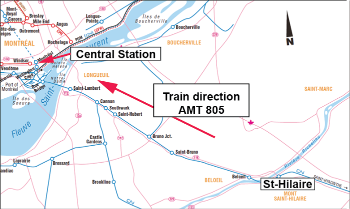
On 09 December 2011, Agence Métropolitaine de Transport (AMT) train No. 805 (the train), a regularly scheduled commuter train, departed Mont-Saint-Hilaire, Quebec, at 0700Footnote 1 westward en route to Central Station in Montréal, Quebec (Figure 1). The crew consisted of a locomotive engineer and a conductor. Both crew members were qualified for their respective positions, met fitness and rest standards, and were familiar with the subdivision.
The trip from Mont-Saint-Hilaire was without incident. At approximately 0747, just before the train entered Central Station, the locomotive engineer shut down the power on the lead locomotive as per normal operating procedure.Footnote 2 The locomotive engineer, positioned in the lead locomotive, was using the power of the rear locomotive to propel the train. The air brakes in the train consist were operative, but were not being used. The throttle had been placed in the idle position during the approach to the station.
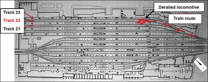
As the lead portion of the train was exiting an 11.75° left-hand curve (in the direction of train travel) entering the station platform area on Track 22 (Figure 2) at 11 mph, there was an unusual jolt and the locomotive engineer made an emergency application of the train air brakes. When the train stopped, the crew determined that the lead locomotive (AMT 1352) and the first coach (AMT 3000) had derailed and had come to rest against the concrete boarding platform that was on the south side of the track.
The passengers were instructed to move to the head end of the train where they were able to egress normally onto the Track 22 boarding platform. There were no injuries.
The temperature was 2°C.
Site information
Central Station is located at Mile 74.25 at the end of the Canadian National (CN) Saint Hyacinthe Subdivision, which originates at Sainte-Rosalie, Quebec. Central Station is Canada's second busiest train station. It is an underground terminal located in downtown Montréal and consists of 20 tracks used almost exclusively by AMT, VIA Rail Canada Inc. (VIA), and Amtrak for commuter and intercity passenger travel. Train movements within Central Station are controlled by the Centralized Traffic Control system authorized by the Canadian Rail Operating Rules and supervised by a rail traffic controller located in Montréal.
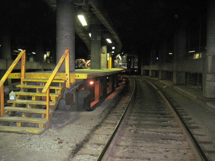
A concourse level is located above the station tracks. There are concrete platforms situated on one side of each track for passenger boarding. Passengers can access the boarding platforms from the concourse level by use of stairs and escalators. Some of the tracks, including Track 22, are dead-end tracks that are equipped with a stopping post (bumper) at their west end. Lighting is concentrated mainly on the passenger boarding platform areas. Secondary lighting comes from the many dwarf signals throughout the station and a minor amount of natural light from the eastern entrance.
The lead locomotive stopped approximately 440 feet west of the start of the boarding platform of Track 22. The trailing wheel set of the lead truck of the lead locomotive was derailed to the north side of the track. The other 3 wheel sets of the locomotive had their south wheels derailed inside the gauge. On the derailed coach, the lead wheel set of the lead truck also dropped inside the gauge.
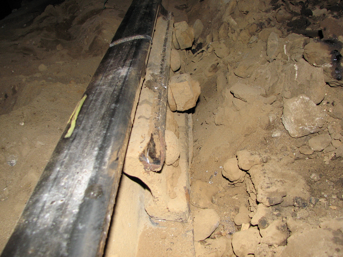
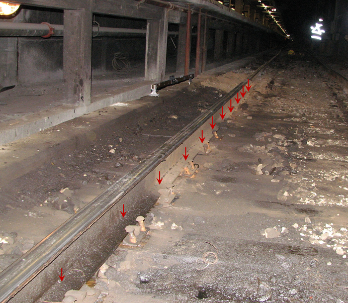
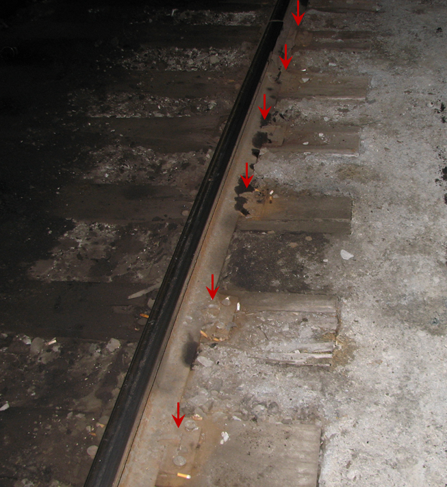
The first impact marks were observed on a rail joint on the south rail located approximately 200 feet west of the start of the boarding platform and 10 feet west of the end of the curve. Further west, the south rail was rolled to the field side and had been displaced laterally outward in some places by approximately 10 inches (Photo 3). Marks were observed on the inside of the rails along the web and base of the south rail, on the tie plates, as well as on the ties, up to the front of the lead locomotive. The north rail had remained in place. The spikes on the gauge side of the north rail at the end of the curve were raised by approximately ¾ to 1 inch.
Train information
The train consisted of 2 recently acquired Bombardier Transportation (BT) dual-powered locomotives that is AMT 1352 at the head end of the train and AMT 1353 at the tail end and 9 bi level passenger cars. The train weighed approximately 980 tons and was about 910 feet long.
Locomotive AMT 1352 was delivered to AMT in July 2011. After final testing and commissioning, it was inspected by Transport Canada (TC) on 25 November 2011. It was placed in revenue service on 28 November 2011, approximately 2 weeks before the accident. Since its implementation date, the locomotive had acquired approximately 1070 miles of service for AMT, mostly on the Saint Hilaire line.
The train received a pre-service inspection and No. 1 brake test on the morning of the accident in Mont-Saint-Hilaire. No defects were observed.
The new locomotives had operated in Central Station 33 times, namely 15 times on Track 21, 5 on Track 22, 8 on Track 23, and the remaining on other tracks.
Equipment acquisition – AMT
As a result of increased ridership and expansion plans, AMT received funding approval from the Province of Quebec to acquire 160 passenger cars and 20 dual-powered locomotives from BT. Technical specifications for the new equipment were prepared in 2007, the contract was granted in August 2008 and the new equipment started arriving in Montreal in June 2011. The new equipment was used to supplement existing AMT equipment.Footnote 3 To save on the procurement cost, the locomotives were part of a joint tender with New Jersey Transit (NJ Transit).
Since 2007, numerous meetings have been held between AMT and Canadian National, as well as with Canadian Pacific Railway (CPR), to identify and address issues related to the commissioning of the new equipment. AMT met with the railways during the preparation of the technical specifications, during construction, and during testing. Invitations were extended to the railways by AMT to participate in the inspection of the locomotive assembly in Germany, to become familiar with the locomotive equipment upon arrival at NJ Transit, and to participate during testing in Pueblo, Colorado.
AMT and TC representatives examined the new locomotives during manufacturing in Germany. A new locomotive was shipped to the Association of American Railroads (AAR) Transportation Technology Center near Pueblo. It underwent testing in a North American environment over a period of 6 months. Canadian National and CPR crews who would be operating the new locomotives on the AMT trains attended training classes in Montréal.
Locomotive characteristics
The dual-powered locomotive was built to comply with AAR and American Public Transportation Association Manual of Standards and Recommended Practices, as well as Federal Railroad Administration (FRA), TC, and Province of Quebec requirements (including environmental and emission prerequisites). It was designed to operate safely at speeds up to 125 mphFootnote 4 with up to 6 inches of cant deficiency.Footnote 5 It underwent American Public Transportation Association Manual of Standards and Recommended Practices static truck equalization testing (APTA SS-M-014-06) and exceeded its requirements. Technical specifications of the dual-powered locomotive are listed as follows:
| Overall length | 71.5 feet |
|---|---|
| Gross weight | 281 040 poundsFootnote 6 |
| Number of axles | 4 (all powered) |
| Approx. weight/wheel | 35 125 pounds |
| Classification | ALP-45DP |
| Wheel type | Class B (110-inch wheelbase) |
| Wheel profile | AAR – 1:40 taperFootnote 7 |
| Max design speed | 125 mph (80 mph on AMT) |
| Brakes | Disk & Tread + Dynamic |
| Operating mode | Electric or diesel |
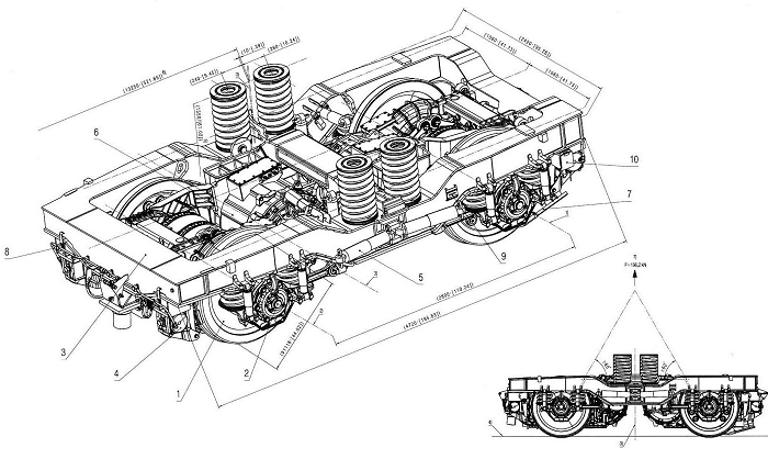
The locomotive truck arrangement was based on a proven BT design used extensively since 1980. Unlike many North American locomotives, the car body of the locomotive is not seated on a bolster. Rather, the car body is supported on each truck by 4 helical Flexicoil springs, with outer and inner coils. These springs deflect vertically under the locomotive weight, and they are sheared laterally as well as longitudinally during truck rotation to help the truck return to its normal orientation upon exiting a curve (Figure 3).
There are over 1000 BT locomotives in service worldwide with a similar truck arrangement. Some of them have axle loads up to 35 tons and have been operating heavy-haul in Europe since 2000. However, most of them have a lighter axle load than the ALP-45DP. Approximately60 of these locomotives (type ALP-46), several of which were manufactured since 2002, are in service for NJ Transit. Their weight is approximately 207 000 pounds. Other bolsterless passenger locomotives (type P42-DC and PL-42), operating on Amtrak, NJ Transit, and VIA for more than 10 years, have a gross operating weight ranging between 282 000 and 295 000 pounds.
On 20 December 2011, BT personnel conducted a teardown inspection of AMT 1352 in AMT shops in Pointe-Saint-Charles, Quebec, in the presence of TSB investigators. During this inspection, the mechanical characteristics of the locomotive were compared against the manufacturer's specifications. Nothing abnormal was noted. The quality-control documents from the spring manufacturer were also examined. The spring material and related test requirements were found to meet BT specifications.
Particulars of the track
Track 22 starts at a No. 8 special turnout. It consisted of a 270-foot left-hand curve, followed by approximately 1000 feet of tangent track ending at a stopping post. The curved portion started approximately 75 feet east of the beginning of the boarding platform, ending 195 feet further west. The track structure consisted of 39-foot jointed rail. The south rail was Dominion 100 pound ARAA HF 1939 (head-free).Footnote 8 The north rail consisted of 100-pound ARAA standard rail followed by 100-pound head-free rail. The transition to head-free rail occurred approximately 60 feet before the end of the curve. The ties were No. 2 hardwood, spaced 18 inches centre to centre, and were in fair condition (Appendix A for tie requirements).
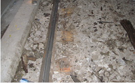
The tie plates used to secure the rail in the derailment area were of a different type and vintage, due to spot maintenance that had occurred over the years. There were 3 types of tie plates: 10 inch, 11-inch, and 14-inch. The 10-inch tie plates were of a unique design, identified with markings Y-1939 CNR. This type was original to the construction of Central Station. The 11-inch and 14-inch were standard double-shouldered tie plates.
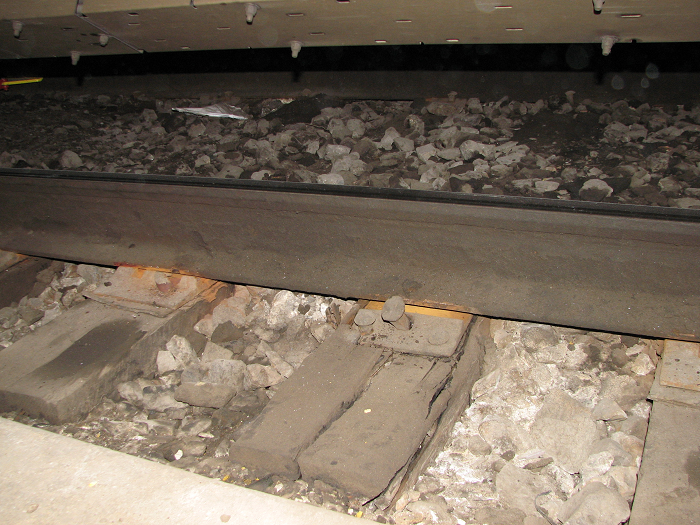
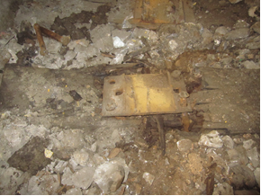
The 14-inch tie plates were used under the ARAA standard rail in the north side of the curve. They were secured with 6 spikes per tie plate. A mixture of 10-inch and 11-inch tie plates was used in the remaining section of the track. There was a cluster of 10-inch tie plates in both rails at the end of the curve (photos 5 and 6). There was a ⅛-inch gap between the tie-plate shoulders and the base of the rail.
The 10-inch tie plates were secured with 4 round spikes and 2 lugs. The 11-inch tie plates were secured with 2 spikes in the tangent and a minimum of 3 spikes in the curved section. Many of the 11-inch tie plates were installed with a ¼-inch rubber insulating pad under the tie plate.
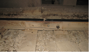
The track was unanchored. Ballast was crushed gravel (1- to 2-inch diameter) with some locations clogged by grease and mud (photos 7 and 8).
Train speed was restricted to a maximum of 10 mph. The track was considered "other than main track" but maintenance requirements were in accordance with Class 1 of the Railway Track Safety Rules (TSR) dated 03 November 2008 (TC E-31) approved by TC.
Examination of track components
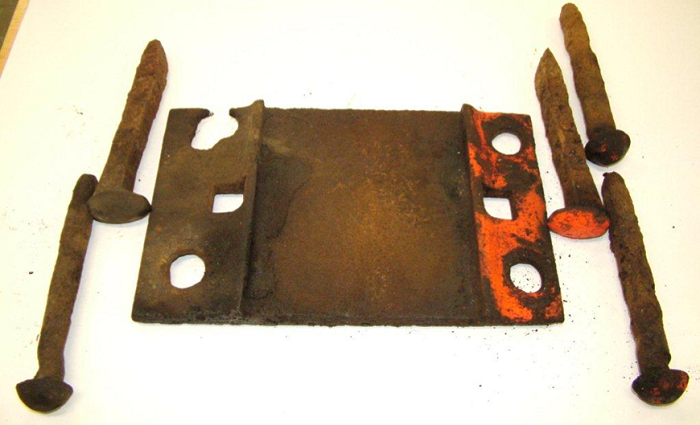
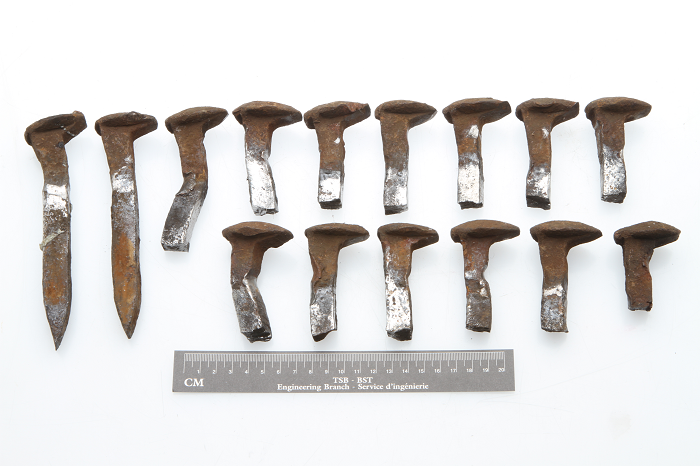
Several of the 10-inch tie plates and round spikes from Track 22 (Photo 9) were sent to the TSB Laboratory (Report LP 099/2012). It was determined that:
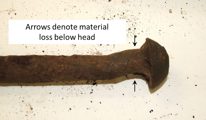
- For the round track spikes, the shanks were corroded just below the head where the spikes came into contact with the tie plates. The diameters of the spikes were reduced by up to 5/16 inch.
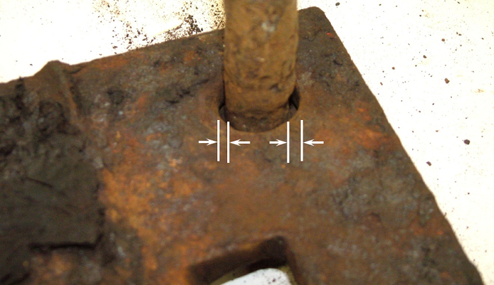
- The spike holes in the tie plates were enlarged by up to ¼ inch.
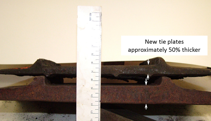
- The base of the 10-inch tie plates was approximately 50% thinner than the base of the 14 inch tie plates.
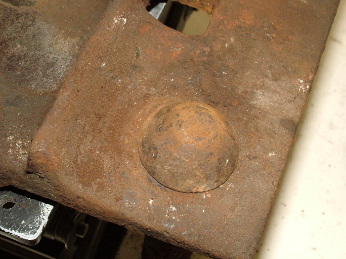
The round track spikes have a head that covers the entire hole in the 10-inch tie plates, making it difficult to assess the wear and corrosion occurring on the shank of the spikes or the tie plate holes (Photo 13).
Track inspections
Track 22 had been inspected by hi-rail on 22 November 2011 and on 04 October 2011. No exceptions were noted in the derailment area. The TSR specify that "other than main track" must be inspected monthly, but do not require rail-flaw detection and track-geometry car testing.
The track was last tested for rail flaws on 16 December 2010 and no exceptions were identified. The track was not tested by a track geometry car.
Post-accident track measurements
Following the accident, track measurements for cross-level and gauge were obtained for 15 stations (measured 15 feet 6 inches apart) starting east of the derailed equipment (Appendix B):
- The measured gauge in unloaded conditions was approximately 57 ¼ inches, which was within the TSR-Class-1-track allowable limit of 58 inches.
- As specified in the Canadian National Engineering Track Standards,Footnote 9 12° curves are designed with ½-inch superelevation for trains operating at 10 mph. The measured cross-levelFootnote 10 on the curve fluctuated between –1 ¼ inches to +⅝ inch, with the negative values occurring at the 3 stations at the end of the curve. The cross-level deviations from designed elevations were within the TSR allowed limits of 3 inches in curves for Class 1 track.
Critical rail gauge
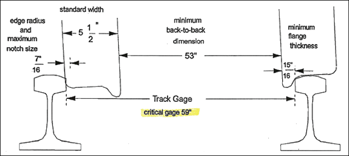
When the loaded gauge exceeds the critical gauge limit of 59 inches defined by the physical dimension of a standard worn freight car wheel set, wheel drop will occur (Figure 4).
For the ALP-45DP locomotive, equipped with new wheel sets, the critical rail gauge would be 59 ½ inches.
Lateral/vertical ratio
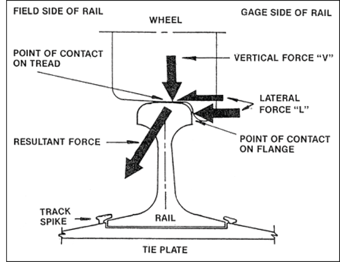
L/V quantifies the ratio between the force of the wheel flange pushing out on the rail (lateral force) and the wheel load of the equipment bearing down on the rail (vertical force). The single wheel L/V ratio can be used to predict the risk of a wheel climbing the gauge face of the rail or lifting off the rail (Figure 5). Similarly, the combined forces for the wheels on one truck side exerting high lateral forces onto the same rail can cause rail-head deflection, reverse-rail cant, or lateral-rail displacement, resulting in gauge spread or rollover. AAR guidelines indicate that truck side L/V values should not exceed 0.6.
Instrumented tests
Following the accident, independent tests were conducted in Montréal and in New Jersey to assess the lateral forces being exerted into the track by the new dual-powered locomotives.
The Montréal tests were conducted by TUV Rheinland Rail Sciences (TUV/RSI), a Scottdale, Georgia-based railroad consulting firm. Two instrumented wayside sites equipped with strain gauges were installed to compare the lateral forces exerted on the track by 2 different types of locomotives. The low-speed tests were performed on 24 March 2012, in the derailment curve at Central Station. The higher-speed tests were performed on 31 March 2012 in a 3° curve in main track on the Canadian National Deux-Montagnes Subdivision.
Two train consists were used. One train was equipped with the new dual-powered locomotives (ALP-45DP) and the other was equipped with the previously used style of locomotive that is, F40-PH manufactured by General Motors Electromotive Division. The results of the instrumented wayside tests are summarized as follows:
| Central Station – Track 22 | Mile 16.5, Deux-Montagnes Sub | |||
|---|---|---|---|---|
| Locomotive type | ALP-45DP | F40-PH | ALP-45DP | F40-PH |
| Max. lateral wheel load | 25 kips | 20 kips | 20 kips | 20 kips |
| Max. truck side L/V ratio | 0.32 | 0.21 | 0.30 | 0.52Footnote 11 |
The New Jersey tests were conducted by Prose Ltd., a Switzerland-based engineering company. Strain gauges were installed directly on the wheels on the lead truck of an ALP-45DP dual powered locomotive that travelled over numerous yard-track and main-track locations throughout the NJ Transit system between 16 and 23 April 2012. Testing was also carried out on the Bayhead Loop, which had an 8° to 12° curve, with a superelevation of approximately 2 ½ inches. In comparison, Track 22 at Central Station has a maximum curvature of 11.75°. The results of the instrumented wheel-load testing for the Bayhead Loop track are summarized as follows:
| ALP-45DP | Run 1 | Run 2 |
|---|---|---|
| Max. laterals | 23 kips | 19 kips |
| Max. truckside L/V ratio | 0.21 | 0.18 |
Computer simulations
Computer simulations using Track 22 data were performed by TUV/RSI to compare the ALP 45DP with other passenger-locomotive types used in Central Station by Amtrak and VIA. The results showed:
| Locomotive type | Wheel taper | Axle load | Lateral force |
|---|---|---|---|
| ALP-45DP | 1:40 | 71 380 pounds | 22.4 kips |
| ALP-45DP | 1:20 | 71 380 pounds | 20.4 kips |
| F40-PH (AMT 287) | 1:20 | 65 500 pounds | 16.7 kips |
| F40-PH (AMT 243) | 1:20 | 65 500 pounds | 21.6 kips |
| P42-DC (Genesis) | 1:40 | 67 000 pounds | 19.8 kips |
Gauge restraint measurement
A gauge restraint measurement system (GRMS) uses hydraulic pressure to apply lateral load outward to each rail. The equipment can be mounted on a dedicated rail car or on a hi-rail vehicle so that testing can be conducted in a dynamic environment while the equipment proceeds along the track. Hand-held testing equipment is also available for static testing in isolated locations.
GRMS systems can apply a range of vertical loads to the rail to suit the circumstances, while maintaining an L/V ratio of approximately 0.7. To avoid any influence from adjacent wheel loads, design requirements specify that the unloaded track gauge must be measured at a point no less than 10 feet from any lateral or vertical load application. The applied vertical and lateral loads, as well as precise gauge measurements, are recorded.
Testing has shown that the relationship between applied load and rail-head deflection is predictive. The system continually measures lateral-rail deflection under these load conditions using algorithms to identify areas where rail-head deflection indicates a weak area. Track maintenance forces can then examine the identified areas to improve the rail-securement conditions (for example, ties, tie plates, anchors, and fastenings). Gauge restraint measuring is not a requirement under the TSR and is not a widespread industry practice in station tracks.
Effect of lateral forces on rail-head deflection
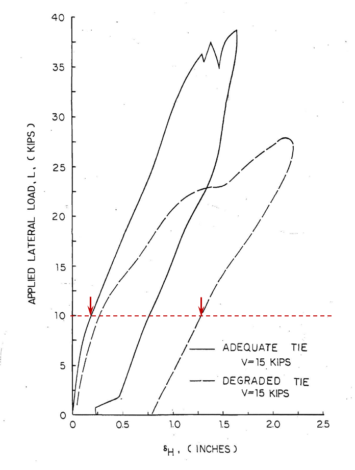
Testing sponsored by the United States Federal Railroad AdministrationFootnote 12 assessed the amount of rail-head displacement under various loads for different track conditions. For example, the application of a vertical load of 15 000 pounds and a lateral load of 10 000 pounds (L/V = 0.66) will result in rail-head displacements between ⅛ inch and 1 ¼ inches, depending on tie conditions (Figure 6).
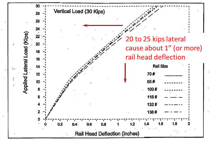
Testing also showed that rail-head deflection is relatively insensitive to the size (weight) of rail. However, head-free rail, due to its lower-lateral stiffness, has more head deflection than other types of rail. With vertical loads of 30 kips, L/V values of 0.7 generate lateral loads of 21 kips, which can cause rail-head deflections of approximately 1 inch (Figure 7).
Effect of wheel contact on rail stability
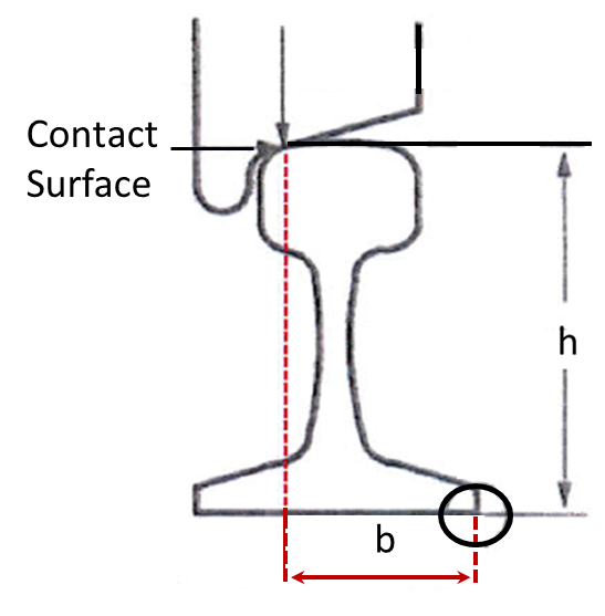
Under lateral loads applied by the wheels, the rail rotates around the field side of the base. The lateral stability of a rail is linked to the b/h ratio between its height and the distance of the application of the wheel load to the field side of the base (Figure 8). Under equilibrium conditions, just before the rail starts to roll, the L/V ratio is equal to b/h.
In normal circumstances, the wheel-to-rail contact surface occurs at the inner gauge corner of the rail head. When the wheel load is shifted towards the field side, b decreases and b/h decreases. Therefore, L/V is also reduced, leading to an increased risk of rail rollover. The b/h ratio can vary from above 0.6 for contact at the gauge side, to approximately 0.2 when the contact surface is at the far-field side.
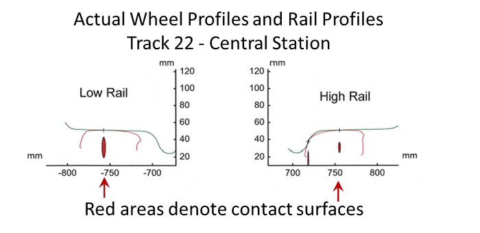
The wheel profiles from locomotive AMT 1352 were compared to the actual rail profiles. Figure 9 identifies the wheel-rail contact points.
Due to the location of the wheel/rail contact points that is, towards the field side of the rail, the b/h values were calculated to be approximately 0.45.
Broken spikes from track 21
After the accident, Track 21 underwent an inspection, as it had also been used by the ALP-45DP dual-powered locomotives. It was noted that there were several broken track spikes in the curved portion of the track at the eastern approach to the boarding platform. The head of the spikes had completely separated from the shanks. Some of the fracture surfaces on these spikes were shiny. Others showed various degrees of oxidation (Photo 14). Examination of these spikes at the TSB Laboratory (Report LP 003/2012) determined that:
- the spikes did not break at the same height;
- the broken spikes failed in fatigue;
- the fatigue cracks varied by their age; and
- the shiny surfaces of the spikes, deformation, and fatigue cracks suggest that there was some significant relative movement of the spikes and tie plates.
The following TSB Laboratory reports were completed:
- LP 003/2012 – Joint Bar and Spike Examination
- LP 099/2012 – Tie Plate and Track Spike Examination
Analysis
There was nothing unusual noted with train handling. The analysis will focus on the rolling stock equipment that is, locomotive AMT 1352, the track conditions, related track maintenance and inspection practices, and track-safety standards.
The accident
As the train approached the platform and negotiated the 11.75° curve, the leading truck of locomotive AMT 1352 exerted lateral forces on the north rail due to steering. These forces, amplified by the geometry characteristics of the curve, that is absence of superelevation and negative cross-level, deflected the rail head and widened the gauge. The resistance of the track to gauge widening was reduced and could not sustain the forces exerted by the leading truck because of the gauge restraint conditions at the end of the curve, that is, wear and corrosion of the round track spikes, enlarged tie-plate holes, gap between the rail base and tie-plate shoulders, and the lower stiffness of the head-free rail. Once the critical gauge of 59 ½ inches was reached, the derailment occurred. The position of the derailed wheels, the marks on the splice bar, and the lateral shift of the south rail were consistent with a wheel drop-in on the south side.
Equipment characteristics
The railways were aware that the gross vehicle weight of the dual-powered locomotive was approximately 7% heavier than the previously used type of locomotives. The heavier weight of the locomotive and the flatter wheel taper of 1:40 contributed to higher wheel loads being transmitted to the track structure. The length of the wheel base (110 inches) had a positive effect of distributing truck side forces on the rail. However, the hold-down effect that adjacent wheel loads can have to minimize gauge widening was negatively affected.
The vertical loads being transmitted to the track structure were similar to other heavy-freight equipment that was commonly accepted on most main-track areas, namely 286 000 pounds gross weight. In comparison with the F40-PH, the ALP-45DP locomotive generated higher lateral forces, and although the lateral forces were up to 25% higher, the L/V values were well within industry and regulatory norms and should not have posed a risk of rail rollover.
Geometry of the curve
The absence of superelevation and the existence of a negative cross-level at the end of the curve were within permissible company and regulatory requirements, that is which allowed up to 3 inches of underbalance. However, these conditions shifted the weight of the locomotive to the outside of the curve and increased the lateral load on the north rail. The lateral load on the rail was also increased by the loss of wheel set steering in the curve caused by the contour of the curved rail and the new locomotive wheels. The wheel-rail contact surface was shifted towards the field side, that is, reduction in the b/h ratio, which resulted in a lower lateral stability of the rail. Furthermore, at the end of the curve, the rail type had changed to head-free rail. Given the lower lateral stability and reduced torsional rigidity of the head-free rail, the ability of the rail to withstand rail-head displacement and reverse-rail cant was reduced.
Gauge-restraint conditions
At the end of the curve, the measured gauge for unloaded conditions was approximately 57 ¼ inches. However, because of the condition of the rail securement, such as the wear and corrosion of the round track spikes, the enlarged tie-plate holes and the gap between the rail base and tie-plate shoulders, the track gauge could reach 57 15/16 inches, even under a relatively low lateral load. Given that the spikes on the north rail were lifted, some rail roll had occurred. The amount of spike lift (up to 1 inch) would have translated into a rail-head displacement of over 1 inch, thus approaching the critical gauge value of 59 ½ inches, resulting in the wheel drop.
Track-inspection practices
The track had received visual inspections. However, the reduced lateral strength of the track was not detected. This visual inspection process relied primarily on the identification of track lateral-strength degradation such as the presence of wood checks or splits, visibly decayed ties, and the looseness of the tie plates and/or its spikes. However, in Central Station, many of the smaller tie plates were mounted on rubber pads that can mask tie-plate movement. In addition, the round track spikes covered the entire hole in the 10-inch tie plates, making it difficult to assess the wear and corrosion occurring on the shank of the spikes or the tie-plate holes. Furthermore, the visual track inspections were performed in relatively low-light-level conditions, which were not conducive to effective inspections.
Relying on visual-inspection methods alone to assess the extent to which track conditions affect the lateral strength of the track might not be sufficient as it is based on a subjective evaluation of the observed conditions. Since visual signs of lateral-track strength are not always fully assessed, and the inspection for lateral strength is a subjective process, there is an increased risk that the weakened lateral strength of some sections of track will remain undetected.
Assessing the track-lateral strength using technology such as GRMS, which applies lateral loads to the rails, would have been beneficial in identifying the track gauge restraint condition. GRMS is typically used in main-track locations, where speeds and tonnages are highest. This method of evaluation allows a quantitative assessment of tie conditions and addresses some of the shortcomings of visual inspection methods. However, passenger trains are not limited to main track locations only. Therefore, for passenger trains that operate on tracks where railways do not use GRMS, there is a risk that the lateral strength of the track may not be adequately assessed.
The use of automated track-geometry measurements under load would also have been beneficial. As these measurements were not taken on Track 22, the opportunity to identify reverse-rail cant or negative cross-level conditions and their effect on gauge-widening forces by locomotives was lost.
Although the overall tie conditions met the requirements of Class 1 track, the condition of the rail-securement devices and their location in a cluster immediately before the point of derailment allowed further gauge-widening under load in the exit of the curve.
Track safety standards
For heavy equipment with vertical wheel loads in the range of 35 kips, the industry-acceptable L/V ratios produce lateral loads in the range of 20 to 25 kips, as was the case with locomotive AMT 1352. The FRA studies showed that lateral loads ranging from 20 to 25 kips can produce rail-head deflections of up to 1 inch depending on the tie conditions. The studies also determined that lateral loads do not decrease significantly even when the rail equipment is operated at speeds below 25 mph. Given that the TSR allows up to 1 ½ inches of wide gauge on Class 1 track, equipment with heavy wheel loads operating on curves with gauge approaching those limits could result in gauge widening to the point of reaching the critical gauge condition of 59 inches for standard worn wheels.
Track 21 spikes
The track spikes from Track 21 had failed due to fatigue and the failures had likely occurred before the introduction of the new AMT locomotives.
Findings
Findings as to causes and contributing factors
- The absence of superelevation and the presence of negative cross-level at the exit of the curve resulted in an increase in the lateral wheel forces.
- Locomotive AMT 1352 generated high lateral wheel forces, which contributed to the destabilisation of the rail, even though the L/V ratio was within industry and regulatory norms.
- The derailment occurred when a wheel of locomotive AMT 1352, a new dual powered locomotive, dropped inside the south rail at the exit of the 11.75° curve on Track 22 due to high lateral wheel forces and existing track gauge restraint conditions.
Findings as to risk
- Reducing train speed below 25 mph does not provide a safety defence to protect against equipment generating high lateral wheel loads as lateral wheel load is insensitive to speed below that value.
- Given that the Railway Track Safety Rules (TSR) allow up to 1 ½ inches of wide gauge on Class 1 track, equipment with heavy wheel loads operating on curves with gauge approaching those limits could result in gauge widening to the point of reaching the critical gauge condition of 59 inches for standard worn wheels.
- In the absence of automated track geometry measurements under load and gauge restraint measurement system (GRMS) inspection, reverse rail cant or negative cross level conditions and weak lateral-track strength are difficult to identify when employing visual inspection only, increasing the risk that track gauge widening will occur, leading to derailments.
Other finding
- The track spikes from Track 21 had failed due to fatigue and the failures had likely occurred before the introduction of the new AMT locomotives.
Safety action
Canadian national
Immediately after the accident, Canadian National (CN) increased the frequency of visual-track inspections at Central Station from once a month to once a week. Canadian National also repaired and upgraded tracks 19 through 22, by installing new tie plates with double shoulders and elastic fasteners on every second tie.
Transportation safety board
On 05 April 2012, the TSB issued Rail Safety Information letter (RSI-05/12) entitled Condition of Track 22 at Montréal's Central Station, Quebec. The letter noted that, although tracks 19 through 22 had undergone repairs and upgrades, some of the new tie plates were anchored to the ties with lag screws, which had damaged many of the ties by causing them to split. The railway subsequently advised that the damaged ties will be replaced during the winter of 2012.
Transport canada
Transport Canada (TC) inspected the repaired tracks after the accident and determined that their tie conditions met the Track Safety Rules (TSR) for Class 1 track. Transport Canada stated that there was however a concern for the medium- to long-term condition of the damaged track ties. Canadian National provided a maintenance plan related to the track ties on tracks 19 through 22 and TC is monitoring the railway's maintenance activities until all the damaged ties are replaced.
The TSR were revised (25 May 2012 - TC E-54). In the case of Class 1 track where passenger trains are operated, visual inspections must be done weekly or before use of passenger traffic if the track is used less than once a week, instead of monthly as prescribed in the previous TSR for non-main track.
Agence métropolitaine de transport
Agence Métropolitaine de Transport (AMT) has launched several initiatives to reduce the lateral curving forces on the new ALP-45DP locomotives. The wheel treads will be reprofiled to a 1:20 taper by the end of 2012 which, according to computer simulations, will reduce lateral curving forces in Central Station by approximately 9%. AMT and Bombardier Transportation have also committed to install within 12 months truck-mounted wheel lubricators to improve the wheel to-rail coefficient of friction. AMT anticipates that the use of wheel lubricators will further reduce lateral curving forces in Central Station between 7% and 35%. Furthermore, computer simulations are being performed to assess the ALP-45DP locomotives against the Association of American Railroads (AAR) freight car Manual of Standards and Recommended Practices, Specification M-1001, Chapter XI.
Safety concern
The installation of truck-mounted wheel lubricators and reprofiled 1:20 wheel tapers will reduce the lateral forces exerted by the new ALP-45DP locomotives. The reduced forces should be closer to the F40-PH locomotives presently used by AMT. However, an increasing number of passenger locomotives, such as the P42-DC and the PL-42, used by Amtrak, VIA Rail Canada Inc. and New Jersey Transit, are heavier than the F40-PH. They have comparable weights to the ALP-45DP, and can generate high lateral loads.
These heavier locomotives generate vertical wheel loads in the range of 30 to 35 kips and can exert lateral loads in the range of 20 to 25 kips on curves. Although this equipment meets the L/V ratio, Federal Railroad Administration (FRA) studies have demonstrated that lateral loads of this magnitude can produce rail head deflections of up to 1 inch.
There are numerous movements daily across Canada involving these heavy passenger locomotives on Class 1 track and yard tracks. Although the new TSR requirements will increase the type and frequency of certain inspections for some of these tracks, there are still no requirements to perform instrumented inspections on tracks such as Central Station tracks, where tonnage traffic is less than 5 million gross tons per mile (MGTM), using technology such as track-geometry cars or the gauge restraint measurement system (GRMS).
In these locations, the main defence to ensure that track conditions meet the TSR requirements is visual inspection. Relying on visual inspection methods alone to assess the extent to which track conditions affect the lateral strength of the track may not be sufficient as it is based on a subjective evaluation of the observed conditions. As the requirements for these sections of track are not as stringent as higher classes of track, there is an increased risk that low track lateral strength could be present and may go undetected.
Therefore, the Board is concerned that, where heavy passenger locomotives are operated on lower classes of track, adequate defences may not be in place to prevent excessive gauge widening, increasing the risk of derailments.
This report concludes the Transportation Safety Board's investigation into this occurrence. Consequently, the Board authorized the release of this report on . It was officially released on 24 January 2013.
Appendices
Appendix A – tie requirements for class 1 track (Track safety rules)
Crossties
- Crossties shall be made of a material to which rail can be securely fastened.
- Each 39 foot segment of track shall have:
- a sufficient number of crossties which in combination provide effective support that will:
- hold gauge within the limits prescribed . . . ;
- surface within the limits prescribed . . . ; and
- maintain alignment within the limits prescribed . . .
- the minimum number and type of crossties specified in paragraph(c) of this section effectively distributed to support the entire segment; and
- At least one crosstie of the type specified in paragraph (c) of this section that is located at a joint location as specified in paragraph (d) of this section.
- a sufficient number of crossties which in combination provide effective support that will:
- Each 39 foot segment of:
Class 1 track shall have five crossties . . . which are not:- broken through;
- split or otherwise impaired to the extent the crossties will allow the ballast to work through, or will not hold spikes or rail fasteners;
- so deteriorated that the tie plate or base of rail can move laterally more than 1/2 inch relative to the crossties; or
- cut by the tie plate through more than 40 per cent of a tie's thickness.
Appendix B – Post-accident track 22 measurements
| Station # (15'6" c/c) | Chainage (ft) | Alignment Mid-Ordinate (62' chord) | Gauge | Unloaded X-Level | Curvature (degree) | Radius (R=50/Sin(Do/2) |
|---|---|---|---|---|---|---|
| Switch point | 0 | |||||
| 0 | 76 | 56 7/8" | 0" | |||
| 1 | 91 | 56 ½" | 0" | |||
| 2 | 107 | 1 ¼" | 56 ½" | + ¼" | 1° 15' | 4583.75' = 1397.13 m |
| 3 | 122 | 56 5/8" | + ½" | |||
| 4 | 138 | 5 ½" | 56 ½" | + 5/8" | 5° 30' | 1042.14' = 317.64 m |
| 5 | 153 | 56 5/8" | + 5/8" | |||
| 6 | 169 | 11" | 57" | 0" | 11° | 521.67' = 159.01 m |
| 7 | 184 | 56 ¾" | + 1/8" | |||
| 8 | 200 | 8 ¼" | 56 5/8" | + ¼" | 8° 15' | 695.09' = 211.86 m |
| 9 | 215 | 56 5/8" | + ¼" | |||
| 10 | 231 | 56 ¾" | 0" | |||
| 11 | 246 | 57 1/8" | 0" | |||
| 12 | 262 | 57 ¼" | 0" | |||
| 13 | 277 | 56 ¾" | + ¼" | |||
| 14 | 293 | 56 ¾" | + 1/8" | |||
| 15 | 308 | 57 ¼" | + 1/8" | |||
| 16 | 324 | 56 ¾" | (- ½") | |||
| 17 | 339 | 56 5/8" | (- 3/8") | |||
| 18 | 355 | 56 7/8" | (- 1 ¼") | |||
| 19 | 370 | 58 1/8" | - | |||
| 20 | 386 | n/r | - |
NOTE: Station No. 0 is located at the heel of frog (75.86' from switch point for Track 22 switch).
