27 February 2023
Director General, Rail Safety, Transport Canada
Enterprise Building, 14th floor
427 Laurier Avenue West
Ottawa ON K1A 0N5
Subject :
Rail Transportation Safety Advisory Letter 02/23 (occurrence R23S0009)
Deficient track conditions on Canadian Pacific Railway Company’s Swift Current Subdivision
On 16 January 2023, at about 0120Footnote 1, Canadian Pacific Railway Company (CP) train 113-12 was proceeding westward at about 58 mph on a Clear signal on the main track of the CP Swift Current Subdivision near Chaplin, Saskatchewan (Mile 54). The train was equipped with 1 head-end locomotive, 1 mid-train locomotive and 1 tail-end locomotive hauling 1 loaded autorack car and 61 intermodal cars, consisting of a total of 171 car body platforms, loaded with single and double-stacked containers. The train was 10 961 feet long and weighed 9478 tons.
The Swift Current Subdivision is one of the busiest CP subdivisions in Canada, with traffic averaging 23 trains per day. Train movements in the area are governed by the centralized traffic control system, as authorized by the Canadian Rail Operating Rules, and dispatched by a CP rail traffic controller located in Calgary, Alberta. The track in the vicinity of the derailment consists of single main track. It is Class 4 track according to the Transport Canada (TC)–approved Rules Respecting Track Safety, otherwise known as the Track Safety Rules (TSR), with a maximum authorized speed of 60 mph for freight cars. There were no track slow orders in effect at the time of the accident.
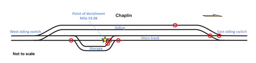
As the train proceeded through the town of Chaplin, a train-initiated emergency brake applicationFootnote 2 occurred as the lead locomotive approached the west siding switch at Mile 54.7. The lead locomotive came to a stop at approximately Mile 55.2 (Figure 1).
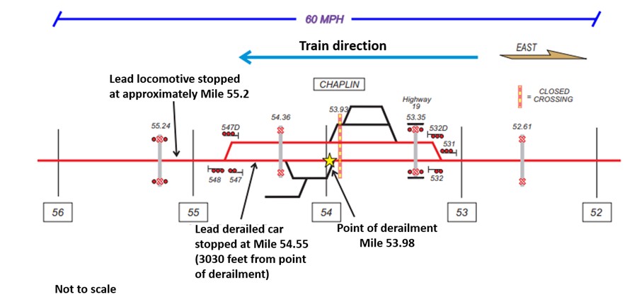
Site examination revealed that 15 intermodal cars (from line 20Footnote 3 to line 34) had derailed. The derailed equipment comprised a total of 47 car body platforms loaded with a total of 96 containers. The trailing truck of line 20 was the first to derail to the south side at Mile 53.98, which was considered to be the initial point of derailment (POD). Impact marks were observed on the wheel treads of the south-side wheels of the freight cars located in the line 19 (not derailed) and line 20 positions. These marks were consistent with a wheel tread contacting a gap in the south rail head at the POD. From the POD, line 20 was dragged about 3000 feet in the upright position, damaging track along the way. Subsequently, the trailing cars in the line 21 to line 34 positions derailed and came to rest in various positions along the right-of-way (Figure 2). Most of the cars and containers were extensively damaged.
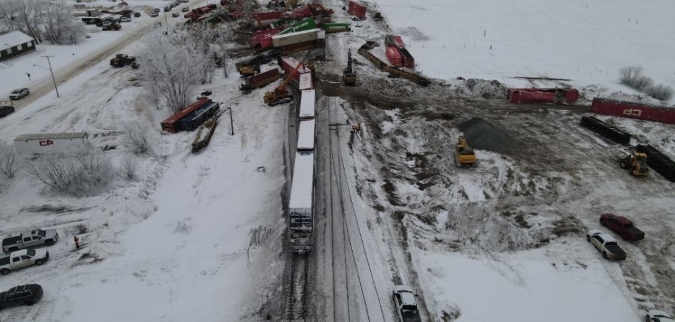
The main track, a siding to the north of the main track and a storage track south of the main track sustained damage and were blocked by the derailed rolling stock. There were no dangerous goods involved and there were no injuries.
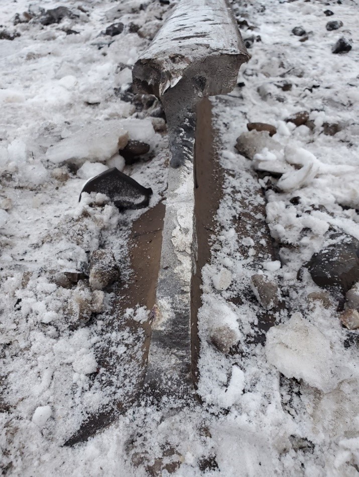
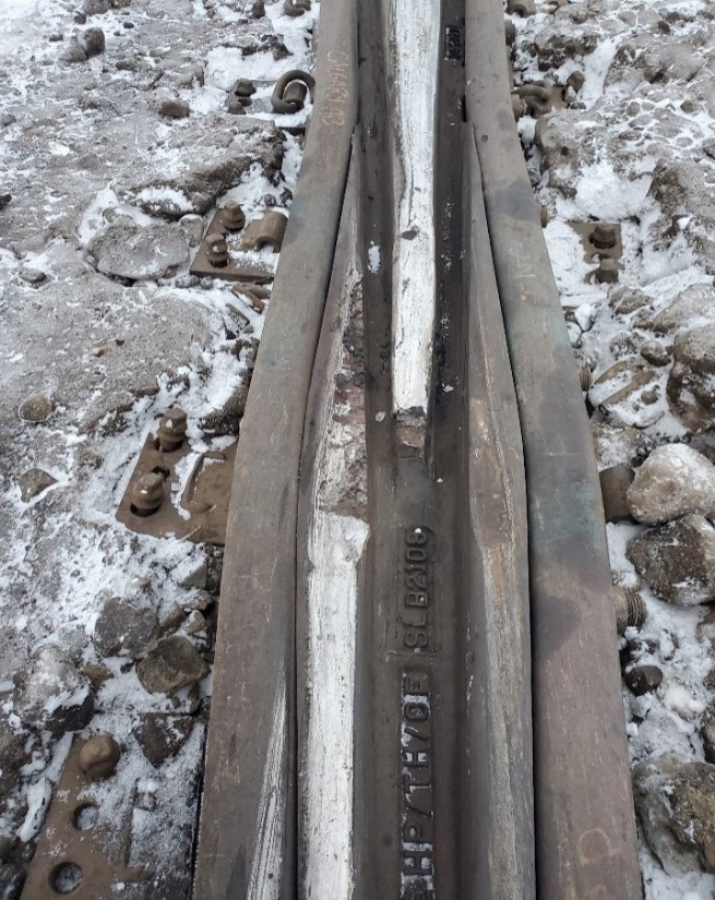
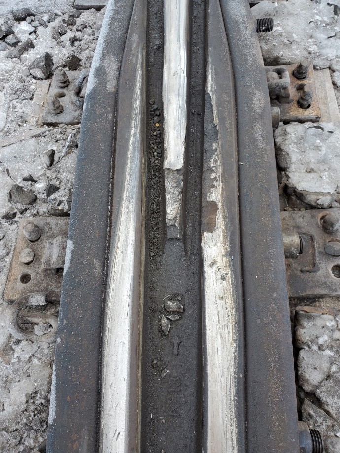
Pieces of the broken south rail (Figure 3), including the POD, were recovered from the site and taken to the TSB Winnipeg Regional Office in Winnipeg, Manitoba, for detailed visual examination. The examination was conducted by TSB Engineering Laboratory personnel and CP Test Department staff on 25 January 2023.

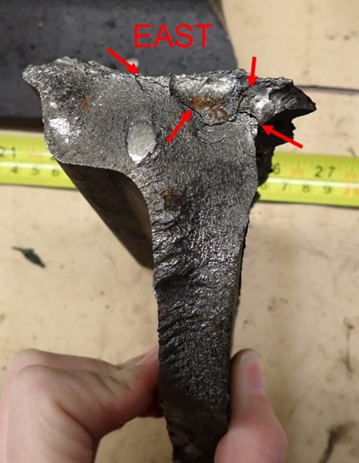
Rail fragment A was part of the south rail at the POD (Figure 4).
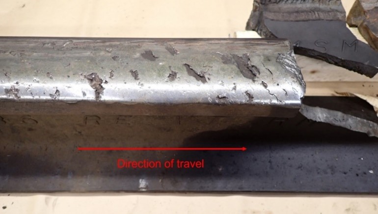
Heavy shelling was observed on the top of the fragment A rail head. Cracks on the rail head were oriented at approximately 45 degrees to the direction of travel (Figure 5), which is consistent with rolling contact fatigue. The gauge face was also heavily worn.
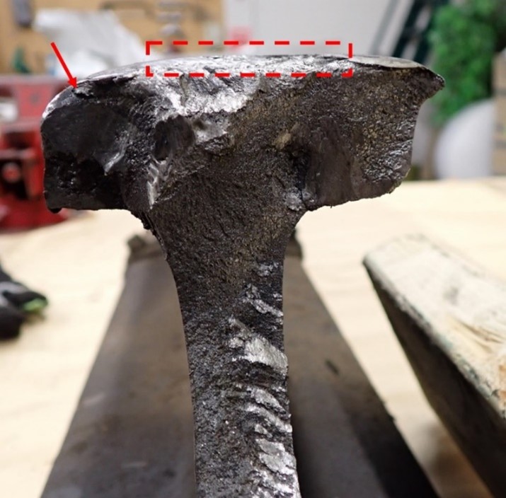
The running surface of the rail head displayed a large shell at the fracture (red box in Figure 6). Gauge-corner cracking was noted along with rubbing of the fracture surface on the rail head gauge side (red arrow) and on the rail web.
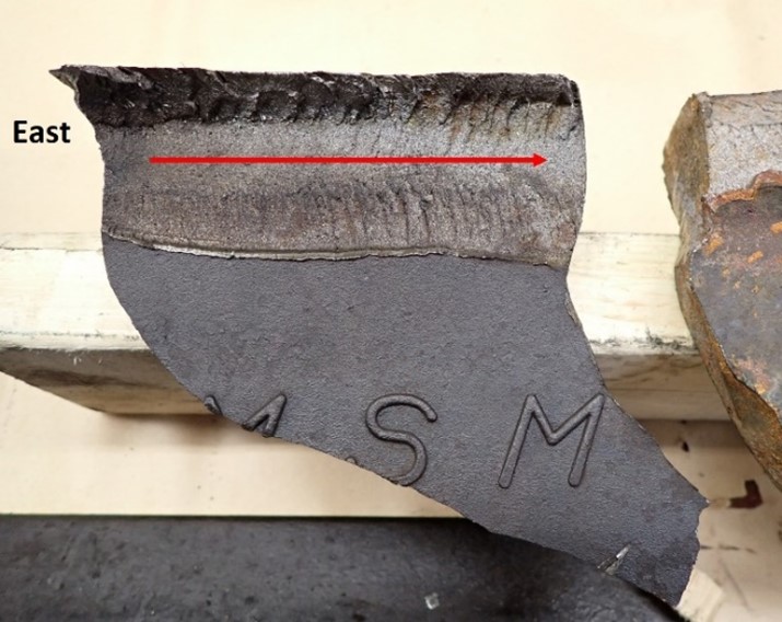
Rail fragment B contained the mating fracture surface to fragment A. Part of the gauge side of the fragment B rail head was missing, exposing a vertical split head (VSH) fracture surface (Figure 7). The VSH fracture surface was slightly corroded, which indicated that it was likely exposed to the elements for a period of time before the derailment. Chevron marks on the VSH fracture surface indicated that the VSH fracture originated at the east end of the fragment and had progressed from east to west (red arrow).
The fragment B east-end fracture surface exhibited multiple cracks (Figure 8). The rubbing damage on the fracture surface matched the damage observed on the mating fragment A fracture surface (Figure 6).
Visual examination determined that rolling contact fatigue on the rail head likely led to the gauge-corner cracking observed on both rail fragments A and B. Gauge-corner cracking resulted in the development of a small transverse defect (TD) that progressed into the VSH defect which was likely present for some time prior to the derailment. Eventually, a portion of the fragment B rail head broke away, possibly under a previous train, exposing the fragment B VSH and leaving a gap in the gauge side of the south rail head. Subsequent catastrophic rail failure occurred under the occurrence train as the train traversed the area and the rail progressively failed, resulting in the derailment. All other rail fractures examined appeared to be fresh and likely occurred as a result of the derailment.
According to documentation provided by CP, the track in the vicinity of the derailment had been inspected in accordance with the TSR and CP’s Red Book of Track & Structures Requirements. The most recent visual track inspection (13 January 2023), heavy track geometry inspection (05 December 2022) and rail flaw detection (RFD) testing (29 December 2022) did not identify any defects in the area. With regards to the RFD testing, it is possible that the heavy shelling on the top of the south rail head masked the presence of any internal rail flaw, such as an emerging TD or VSH.
The most recent TC inspection of the Swift Current Subdivision before the derailment had been conducted between 04 October 2022 and 06 October 2022. During this inspection, the area of the POD on the main track between the siding switches was not inspected. Following the inspection, TC issued a letter to CP identifying 10 non-compliance defects and 60 areas of concern, most of which were for track gauge conditions. CP responded to TC that the 10 non-compliant defects had been repaired and that the 60 areas of concern would be monitored and corrected in 2023 or 2024.
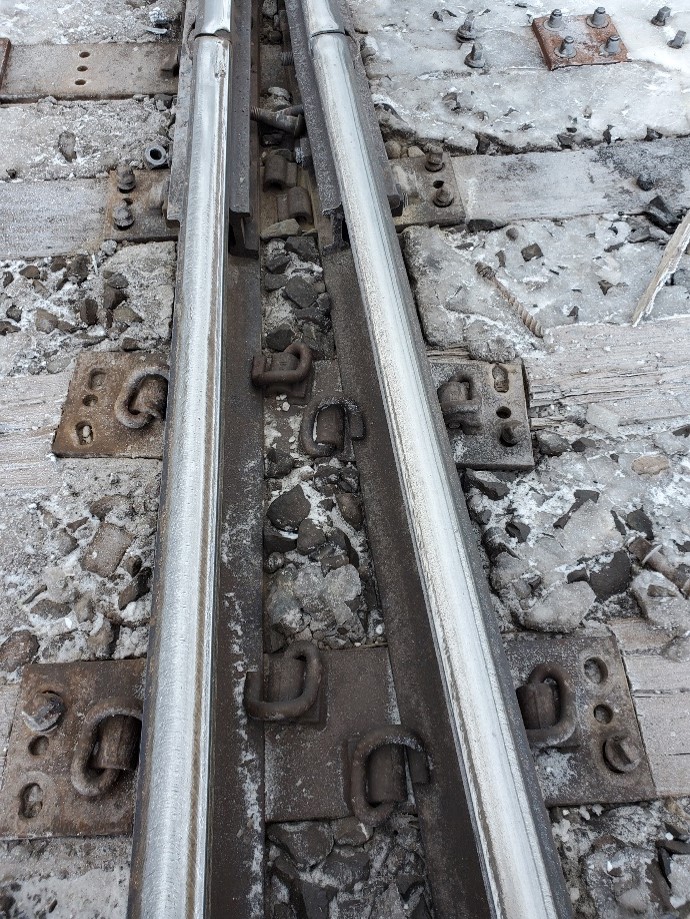
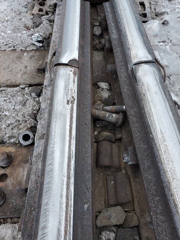
During site activities after the derailment, TSB investigators visually inspected the track in the vicinity of the POD (Mile 53.98) between the east siding switch (Mile 53.1) and the west siding switch (Mile 54.8). The TSB investigators identified the presence of rail corrugation and 7 track deficiencies (Figure 9).
Five of the 7 track deficiencies identified were considered to be defects that required immediate railway remedial action be taken, which may include the application of temporary track speed restrictions, as per the TSR and CP’s Red Book of Track & Structures Requirements. Photographs and observations of each of these deficiencies are contained in Appendix A.
Given the deficient condition of the track observed by the TSB in the vicinity of the POD, there may be gaps in CP’s track inspection and maintenance programs as well as TC’s track inspection and follow-up for the Swift Current Subdivision. Therefore, TC may wish to perform a thorough review of CP’s track inspection and maintenance practices and conduct a detailed regulatory inspection of the entire Swift Current Subdivision.
The TSB would appreciate being informed of what action, if any, will be taken in this regard.
Yours sincerely,
Original signed by
Vincenzo De Angelis
Director, Investigations – Rail/Pipeline
CC:
- Vice-President, Engineering, Canadian Pacific Railway Company
- Director, Regulatory Affairs, Railway Association of Canada
- Acting Regional Director, Surface - Prairie & Northern Region, Transport Canada
- Associate Director General, Rail Safety, Transport Canada
- Director, Regulatory Affairs, Transport Canada
Appendix A – Swift Current Subdivision track deficiencies
As a result of the investigation into the 16 January 2023 Chaplin derailment, the following deficiencies were noted by TSB investigators during an inspection of the main track, siding and storage track between the east and west siding switches, from Mile 53.1 to Mile 54.8 (Figure A1).
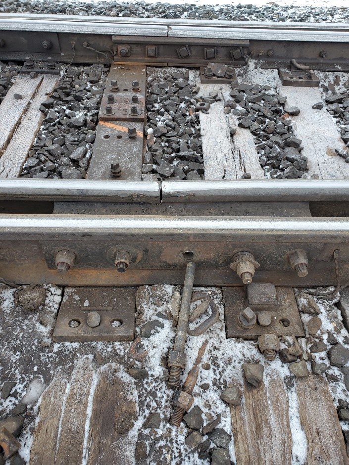
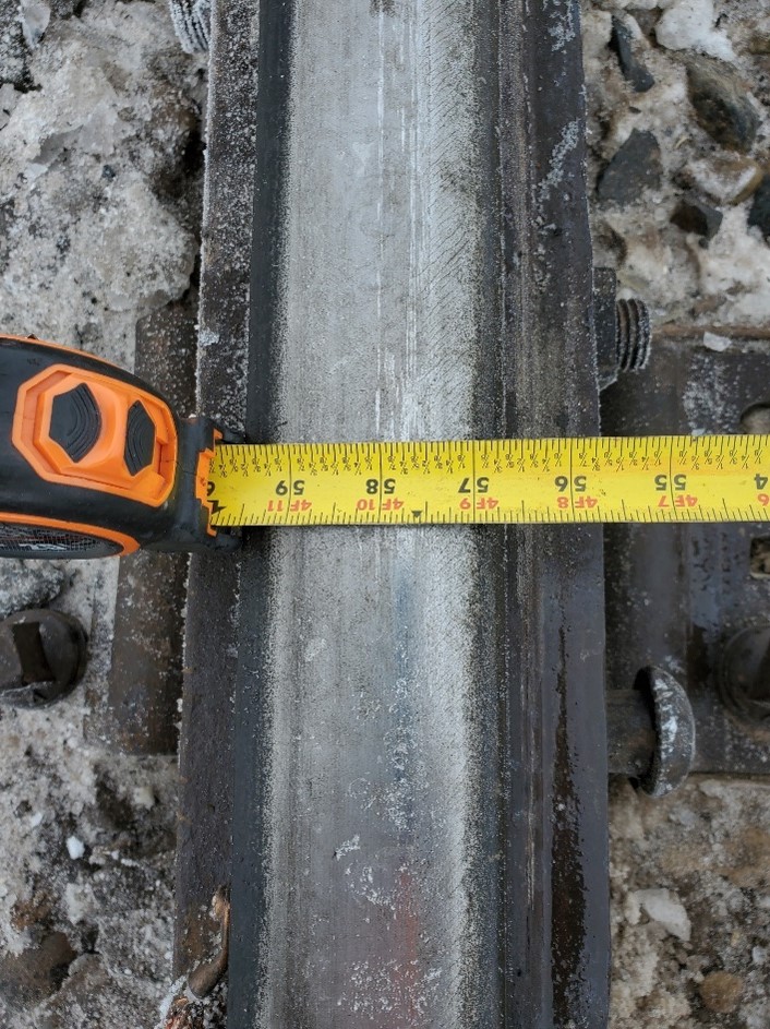
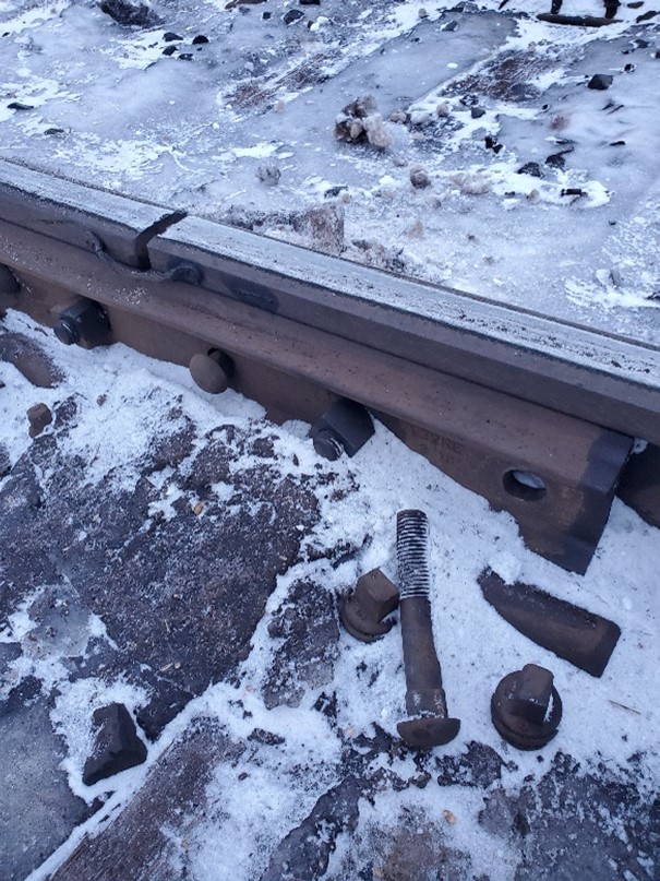
Location 1 (rail joint in the south rail just west of the west storage track switch) – Photos showing loose bolts, missing lag screw, missing rail clips, broken roll plates, and ½-inch wide gauge (Source: TSB)
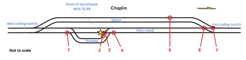

Location 2 (the north rail of the storage track just west of the frog at the east storage track switch) – Photo showing missing rail clips and loose screw spikes (Source: TSB)

Location 3 (the frog at the east storage track switch) – Photos showing a portion of the frog point riser that is missing, braces holding the frog that are broken or missing, wing rails showing unsecured plates, missing clips, lag screws, and loose track bolts (Source: TSB)

Photos showing indications of lateral movement (worn screw spike holes), loose guard rail bolts and narrow-gauge guard rail, which permitted the wheel flanges to contact the frog point (Source: TSB)

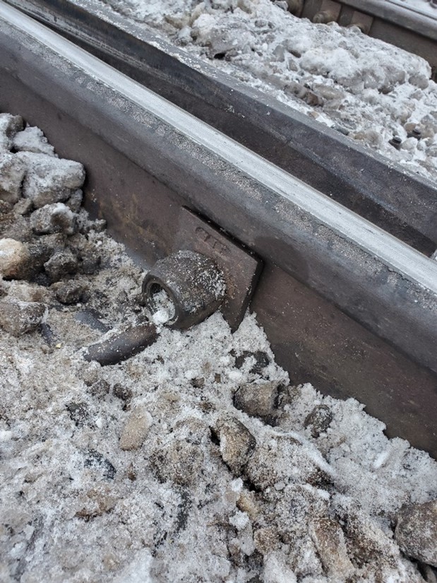
Location 4 (a rail joint in the south rail just prior to the east storage track switch) – Photos showing loose/missing joint bolts; a bolt frozen in the ice indicates that it had been this way for some time (Source: TSB)

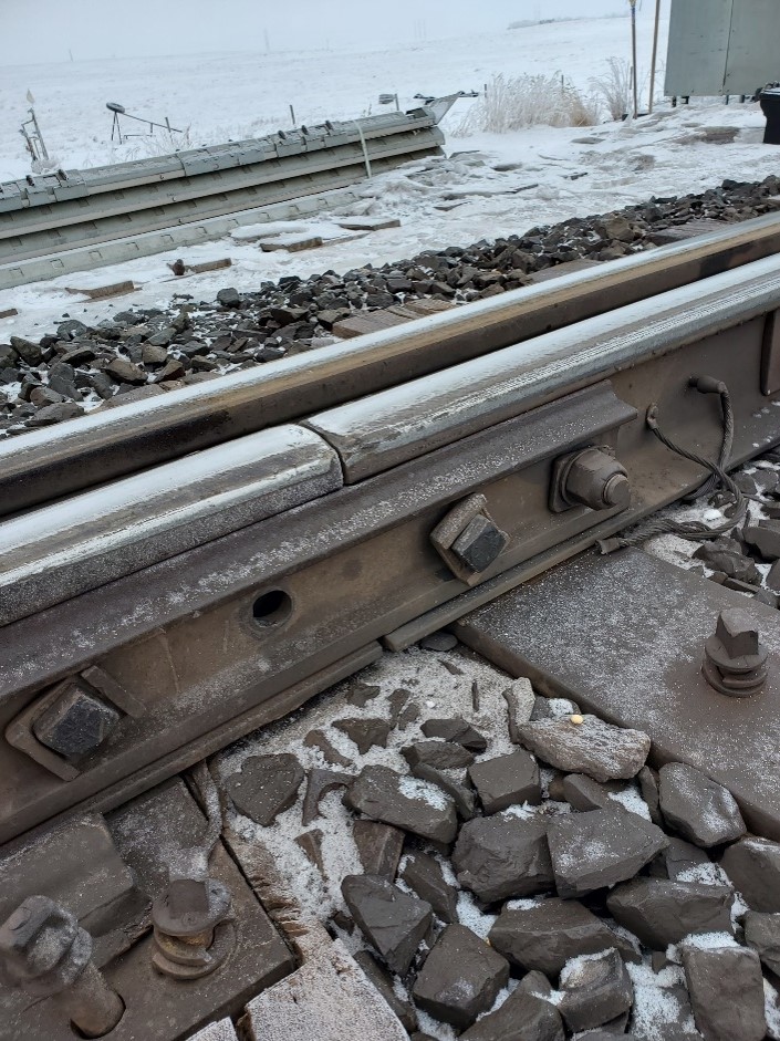
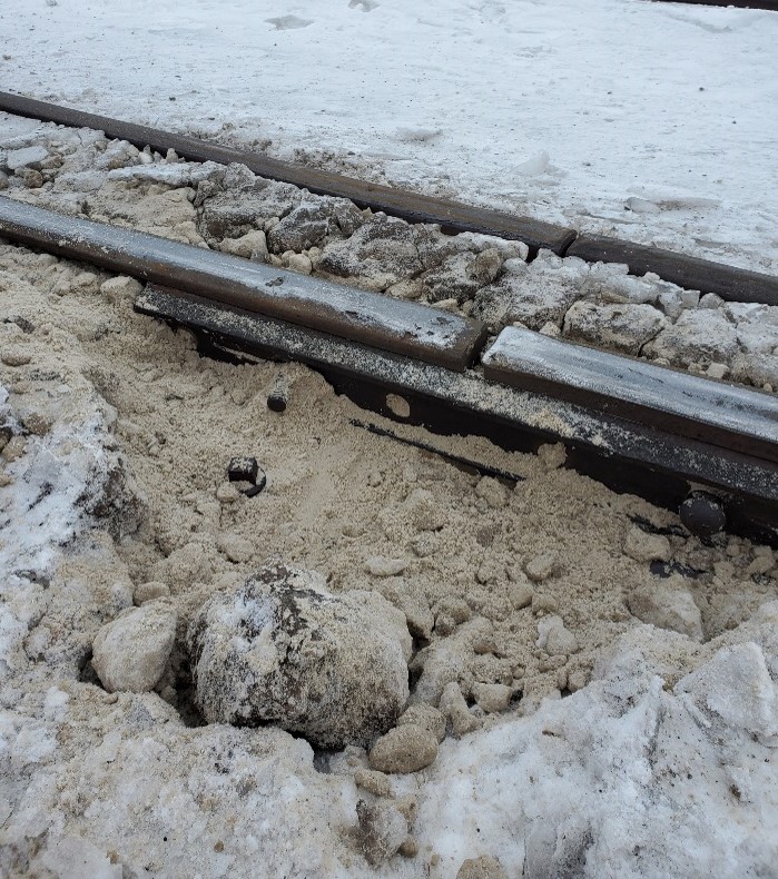
Location 5 (joint pull-apart in the north rail of the siding track) – Photo showing that the joint had 5 bolts missing and the 1 remaining bolt was loose (Source TSB)
Location 6 (the east siding switch frog) – Photos showing that the frog point riser is missing, and that the wing rails exhibit broken or missing clips and hold downs; there are also unsecured tie plates and worn screw spike holes in the tie plates indicating lateral movement, as well as loose and missing track bolts (Source: TSB)
Location 7 (the east siding switch heel casting) – Photos showing broken and loose heel casting bolts, incorrect length of bolt installed, as well as loose/missing screw spikes (Source: TSB)